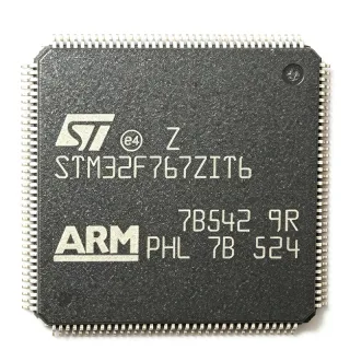
MC9S12H128VFVE - 16-bit HCS12 MCU, 128KB Flash, CAN, QFP-144 | NXP
Teilenummer: MC9S12H128VFVE ✗ Abgekündigt| Menge | Stückpreis | Gesamt |
|---|---|---|
| 1 | $19.85 | $19,85 |
| 10 | $17.62 | $176,20 |
| 100 | $15.2 | $1.520,00 |
| 500 | $13.55 | $6.775,00 |
| 1.000 | $11.92 | $11.920,00 |
MC9S12H128VFVE Übersicht
An HCS12 microcontroller is a 16-bit CISC MCU family from NXP (originally Motorola/Freescale) targeting automotive body and chassis electronics, industrial control, and consumer appliances. Within the broader taxonomy, an HCS12 sits at: HCS12 microcontroller -> 16-bit MCU -> microcontroller -> embedded processor -> semiconductor. The HCS12 instruction set is upward-compatible with the HC11 and HC08 families, which makes porting legacy 8-bit firmware straightforward while doubling addressable performance. The 'H' sub-family emphasizes segment-LCD glass driving, CAN connectivity, and high-noise-immunity analog integration, suiting it for instrument clusters, HVAC panels, and small appliances.
Key features include 128 KB Flash program memory, 4 KB EEPROM, 6 KB SRAM, two CAN 2.0A/B modules, two SCI (UART) channels, one SPI, one IIC (I2C) bus, an 8-channel 10-bit ADC, an integrated LCD driver, PWM channels, and up to 99 general-purpose I/O lines. The HCS12 core delivers 50 MHz bus speed with single-cycle multi-byte instructions, while integrated peripherals include a periodic interrupt timer (PIT), real-time interrupt (RTI), watchdog, and power-on reset.
Architecturally, the MC9S12H128 uses a von Neumann bus with a background debug mode (BDM) for non-intrusive in-circuit programming and debugging. The on-chip oscillator with PLL generates the 50 MHz system clock from a low-cost 4 MHz crystal, reducing BOM cost. The integrated CAN 2.0A/B controllers support both standard and extended identifiers, making the part well-suited for in-vehicle networking.
Typical applications include automotive instrument clusters (with LCD glass), HVAC control panels, body controllers, industrial operator panels with LCD, security system keypads, small-engine ECUs, and consumer white goods with CAN connectivity. The wide operating temperature range of -40C to +105C allows deployment under-the-hood and in industrial cabinets.
When designing with this MCU, allocate the LQFP-144 footprint on a 4-layer PCB with a solid ground pour under the exposed pad. Decouple VDDR/VSS with 100 nF ceramic capacitors placed within 3 mm of each supply pin, and reserve the IRQ and XIRQ lines for noise-immune interrupt sources.
This page consolidates distributor pricing for the MC9S12H128VFVE, lists NXP and pin-compatible HCS12 drop-in alternatives, and adds practical design notes not found in the manufacturer datasheet alone.
Drop-in-Alternativen für MC9S12H128VFVE – gleiches Gehäuse, Pin-kompatibel. Bauteile mit anderem Gehäuse, die eine PCB-Überarbeitung erfordern, sind ausgeschlossen.
Varianten dieser Serie
Modelle derselben Serie, die drop-in-kompatibel sind mit MC9S12H128VFVE (gleiche Bauform und Footprint) – abweichend in Connectivity, Package, Core Processor, Number of I/O, Peripherals.
Schnellvergleichstool – Wählen Sie Alternativbauteile für den Direktvergleich:
MC9S12H256VFVE
✅ Drop-In✓ Auf Lager
$10.95 / Stück
Datenblatt ansehen →MC9S12H128VPVE
✅ Drop-In ⚠️ Spezifikationen ungeprüft✓ Auf Lager
$11.45 / Stück
Datenblatt ansehen →MC9S12H128CFUE
✅ Drop-In ⚠️ Spezifikationen ungeprüft📋 Referenzalternative (nicht im Katalog)
MC9S12DG128VFUE
✅ Drop-In✓ Auf Lager
Preis auf Anfrage
Datenblatt ansehen →MC9S12A256VFUE
✅ Drop-In ⚠️ Spezifikationen ungeprüft📋 Referenzalternative (nicht im Katalog)
MC9S12H128VFVE Grenzwerte & elektrische Eigenschaften
| Core Processor | HCS12 |
| Core Size | 16-Bit |
| CPU Speed | 50 MHz (bus), 16 MHz core instruction rate |
| Program Memory (Flash) | 128 KB |
| EEPROM | 4 KB |
| RAM | 6 KB |
| Gehäuse | 144-LQFP (20x20 mm, 0.5 mm pitch) |
| Connectivity | CAN 2.0A/B x2, SCI x2, SPI, IIC (I2C) |
| ADC | 8-channel, 10-bit |
| LCD Driver | Integrated (segment LCD, up to 64 segments) |
| Number of I/O | 99 |
| PWM Channels | 8 (4x 8-bit or 2x 16-bit configurable) |
| Operating Voltage | 2.5 V to 5.5 V (typical 5 V) |
| Betriebstemperatur | -40C to +105C |
| Montageart | Surface Mount |
| MSL-Level | 3 (168 hours) |
| RoHS-Status | Compliant |
| Lead-Free | Yes |
| Background Debug Mode | Yes (BDM) |
MC9S12H128VFVE Pin-Konfiguration
| Pin 1 | PA0 — Port A bit 0 (GPIO / ATD channel) |
| Pin 36 | VDDR — Voltage regulator supply for internal logic |
| Pin 37 | VSS — Digital ground |
| Pin 72 | VDD — 5 V digital supply |
| Pin 73 | VDDPLL — PLL supply (filtered from VDD) |
| Pin 108 | BKGD — Background Debug Mode (BDM) pin |
| Pin 109 | RESET — Active-low reset input |
| Pin 110 | XTAL — Crystal oscillator input |
| Pin 111 | EXTAL — Crystal oscillator output |
| Pin 144 | TCK — Test clock / JTAG |
Typische Anwendungen
MC9S12H128VFVE ist geeignet für 7 Anwendungs: Automotive Instrument Cluster, HVAC Control Panel, Industrial Operator Panel with LCD, Body Control Module (BCM), Small-Engine ECU / Powersports, Appliance User Interface (White Goods), Security Keypad / Access Control.
Automotive Instrument Cluster
The MC9S12H128VFVE is purpose-built for automotive instrument clusters because its integrated segment-LCD driver (up to 64 segments) eliminates the external LCD controller IC, while dual CAN 2.0A/B controllers connect simultaneously to the body and chassis CAN buses for speed, RPM, fuel, and temperature signals. The HCS12 core at 50 MHz executes gauge sweep, odometer, and trip computer logic with deterministic interrupt latency, and the 128 KB Flash accommodates a complete cluster firmware image including CAN DBC lookups and bootloaders. Operating from -40C to +105C, the part survives under-dash thermal stress and supply transients.
Empfohlen
HVAC Control Panel
For climate-control user interfaces, the MC9S12H128VFVE's segment-LCD driver drives temperature and fan-speed readouts directly, while its SCI and IIC channels interface to the HVAC controller MCU and temperature sensors. The 6 KB RAM handles real-time setpoint and feedback loops without task overflow, and the four PWM channels drive blower-speed MOSFETs at 1 Hz resolution. The 99 GPIO easily accommodate tactile-switch matrices and backlight LED drivers, and the wide operating temperature range ensures reliability behind the dashboard.
Empfohlen
Industrial Operator Panel with LCD
The MC9S12H128VFVE fits industrial HMI panels where the on-chip LCD driver renders process values and alarm icons without extra ICs, and the dual CAN interface integrates with industrial CANopen or DeviceNet networks. With 99 GPIO and eight PWM outputs, the MCU simultaneously drives indicator LEDs, buzzer tones, and keypad scanning while running Modbus-over-RS232 over one of the SCI channels. The -40C to +105C rating handles factory-floor temperature swings.
Empfohlen
Body Control Module (BCM)
Body control modules that orchestrate lighting, wipers, mirrors, and central locking rely on the MC9S12H128VFVE's dual CAN interfaces for gateway between body and powertrain networks, while its 8 PWM channels drive lamp dimming and motor speed control at 1 Hz resolution. The 128 KB Flash stores BCM firmware plus diagnostics and DTC tables in 4 KB EEPROM for service record retention, and 99 GPIO accommodate switch inputs, relay drivers, and LIN-master interfaces through external transceivers.
Empfohlen
Small-Engine ECU / Powersports
In motorcycles, scooters, marine outboards, and small-engine ECUs, the MC9S12H128VFVE provides deterministic fuel-injection and ignition timing via its PWM channels, plus CAN diagnostics for OBD-II scanner connectivity. The 8-channel 10-bit ADC reads throttle position, manifold pressure, and lambda sensors, while the integrated LCD driver displays RPM and fault codes on the handlebar instrument. The 50 MHz HCS12 core completes one combustion cycle calculation in under 100 us, well within 20 ms event timing.
Empfohlen
Appliance User Interface (White Goods)
Washing machines, dishwashers, and ovens use the MC9S12H128VFVE for their user-interface boards because the integrated segment-LCD driver renders cycle status, temperature, and timer readouts directly on the front panel without an external controller. The IIC and SPI channels connect to motor-control and sensor boards, while 99 GPIO handle capacitive-touch buttons and LED indicators. The -40C to +105C range tolerates oven-door and motor-heat ambient rise.
Empfohlen
Security Keypad / Access Control
The MC9S12H128VFVE is suitable for security-system keypads and access-control panels where the segment-LCD displays status, codes, and alarm history, and the SCI interface reports to a central control panel over RS-485. The 4 KB EEPROM stores user credentials and event logs that survive power loss, while the watchdog timer and BDM debug mode assist field service technicians. The wide temperature range supports outdoor and unconditioned vestibule installations.
Empfohlen
Zusammenfassung der empfohlenen Produkte
Technische Referenzdaten für MC9S12H128VFVE – Vergleich, Designhinweise und Compliance-Informationen.
Auswahlhilfe
Vergleich mit Alternativen
| Parameter | Dieses Produkt | MC9S12H256VFVE | MC9S12H128VPVE | MC9S12H128CFUE | MC9S12DG128VFUE |
|---|---|---|---|---|---|
| Brand | NXP Semiconductors | NXP Semiconductors | NXP Semiconductors | NXP Semiconductors | NXP Semiconductors |
| Package | 144-LQFP (20x20 mm) | 144-LQFP - same | 112-LQFP - different footprint | 80-QFP - different footprint | 144-LQFP - same |
| Core | HCS12 16-bit | HCS12 16-bit | HCS12 16-bit | HCS12 16-bit | HCS12 16-bit |
| Flash | 128 KB | 256 KB | 128 KB | 128 KB | 128 KB |
| RAM | 6 KB | 12 KB | 6 KB | 6 KB | 6 KB |
| CAN Controllers | 2 x CAN 2.0A/B | 2 x CAN 2.0A/B | 2 x CAN 2.0A/B | 1 x CAN 2.0A/B | 2 x CAN 2.0A/B |
| LCD Driver | Integrated (up to 64 segments) | Integrated (up to 64 segments) | Integrated | Integrated | None (external required) |
| I/O Count | 99 | 99 | ~70 | ~53 | 99 |
| Operating Temperature | -40C to +105C | -40C to +105C | -40C to +105C | -40C to +85C | -40C to +105C |
Wichtigste Unterscheidungsmerkmale
- Integrated segment-LCD driver (vs. MC9S12DG128VFUE)
- Dual CAN 2.0A/B controllers on-chip (vs. MC9S12A256VFUE)
- Larger Flash with same footprint (vs. MC9S12H256VFVE)
Designhinweise
Estimated: at 50 MHz with all peripherals active, the HCS12 core draws approximately 60 mA from VDD (3.3 V), so total MCU current is ~200 mA including analog blocks. Provide a 100 nF X7R ceramic decoupling capacitor within 3 mm of every VDD/VDDR/VSS pair, plus a 10 uF bulk capacitor near the regulator output. Power VDDPLL through a 1 ohm resistor and 100 nF capacitor to suppress PLL jitter.
Route the EXTAL/XTAL crystal traces as short, symmetric, and guarded by a ground pour to minimize EMI pickup. Place the BDM pin (BKGD) on the board edge accessible to a debug probe without disturbing other signals. The 144-LQFP fine-pitch 0.5 mm leads require a PCB land pattern with a 1:1 pad-to-lead ratio and 0.2 mm solder mask expansion to prevent solder bridges during reflow.
Do not connect the PLL filter pin to a noisy rail; it requires its own filtered RC network. The MC9S12H128VFVE NRND status means NXP does not recommend it for new designs - plan migration to the S12Z MagniV family (e.g., S12ZVL32) for production programs. When migrating firmware from HC08 to HCS12, remember the HCS12 has a 16-bit wide data bus so legacy 8-bit pointer math must be reviewed.
Estimated: at 5 V supply and 50 MHz, the MC9S12H128VFVE consumes roughly 1 W of power. With a typical LQFP-144 thermal resistance of theta_JA ~45 C/W on a 4-layer PCB, the junction rises ~45 C above ambient at room temperature. Continuous operation at +105C ambient keeps junction below the 125 C maximum with adequate copper thermal relief.
Compliance-Informationen
RoHS compliant per NXP product page; AEC-Q100 grade 2 qualified by -40C to +105C temperature rating; suitable for body and chassis automotive electronics.