CI de interfaz
Subcategorías
Productos (1020)

SJA1105PEL - 5-Port Automotive Gigabit Ethernet Switch LFBGA-159 | NXP
The NXP SJA1105PEL is a 5-port automotive-grade store-and-forward Gigabit Ethernet switch housed in a 159-ball LFBGA (12x12 mm) package, extending the SJA1105/SJA1105T family with improved security-related features, extended interface options, and ISO 26262 ASIL-A compliance. The P variant supports Ethernet and AVB, exposing five ports capable of 10/100/1000 Mbit/s including MII, RMII, RGMII, and SGMII interfaces, and integrates a SPI host interface for management and configuration. An automotive Ethernet switch is a Layer-2 networking IC that connects multiple in-vehicle ECUs over twisted-pair copper or fiber, replacing legacy CAN/LIN/FlexRay backbones with deterministic, high-bandwidth links. The SJA1105 family sits within the broader category of Ethernet switches -> Layer-2 networking ICs -> communication controllers -> semiconductor ICs. The switch provides cut-through and store-and-forward forwarding, IEEE 802.1Q VLAN tagging, IEEE 802.1AS time synchronization, and AVB/TSN quality-of-service extensions, making it suitable for ADAS domain controllers, zonal gateways, and infotainment backbones. Key features include five integrated PHY/MAC ports, hardware-accelerated security with a frame-listing mechanism that limits forwarding to known sources to prevent erroneous or malicious frame injection, a 1 Gbit/s SGMII uplink for connecting to an external SoC, an SPI management interface for host control, and industrial-grade temperature range. The device supports jumbo frames and integrated address-table memory, allowing deep switching tables without external SRAM. The new frame-listing feature explicitly limits the switch data processing to known sources, blocking unknown or hostile traffic. The SJA1105PEL is pin-compatible with the SJA1105EL/TEL switches, allowing drop-in upgrades on existing designs while adding the security and feature enhancements of the P/Q/R/S family. The /P and /Q variants do not include an SGMII port and remain 100 percent pin-compatible with the SJA1105/SJA1105T switches, while the /R and /S variants add the SGMII interface. ASIL-A compliance reduces the safety-critical ECU design load for ISO 26262 systems, and a safety manual is available on request from NXP. Typical applications include automotive ADAS sensor fusion gateways, body and chassis zonal controllers, in-vehicle infotainment (IVI) Ethernet backbones, industrial Ethernet switches for harsh environments, and time-sensitive networking (TSN) endpoints. The wide operating-temperature range and automotive-grade qualification also suit heavy-machinery and rail transport networks. When designing with this device, allocate adequate BGA-159 PCB land pattern with via-in-pad or dog-bone fan-out, and verify SPI driver support with the chosen host MCU before committing to layout. This page synthesizes distributor pricing for the SJA1105PEL, drop-in pin-compatible variants in the SJA1105 family, and practical layout notes for automotive Ethernet gateways not found in the manufacturer datasheet alone.
SJA1105SELY - 5-Port AVB/TSN Automotive Ethernet Switch | NXP
The NXP SJA1105SELY is a five-port automotive-grade gigabit Ethernet switch supporting Audio Video Bridging (AVB) and Time-Sensitive Networking (TSN) with SGMII interfaces, housed in a 159-pin LFBGA (12x12 mm) package. It operates from a 1.65V to 3.6V supply and integrates five IEEE 802.3 ports plus an SPI host interface for switch configuration and management. An automotive Ethernet switch is a specialized Layer-2 networking IC that interconnects multiple ECUs (Electronic Control Units) inside a vehicle, falling within the hierarchy of Ethernet switch -> network switch -> communication IC -> semiconductor. The SJA1105 family extends NXP's earlier SJA1105EL/TEL devices with hardened security features, frame listing (whitelisting), and wider interface options including RGMII/SGMII for gigabit uplinks. The switch core implements a 5-port store-and-forward architecture with MAC table management, VLAN processing, and cut-through forwarding. Key features of the SJA1105SELY include 1 Gbit/s per port line rate, integrated AVB/TSN hardware timestamping, hardware-accelerated security (frame listing / MAC authentication), 1.65V-3.6V I/O flexibility for legacy 3.3V PHY compatibility, and AEC-Q100 Grade 2 automotive qualification. The LFBGA-159 package with 12x12 mm body enables compact gateway and domain controller PCB placement. SPI host interface allows the application MCU to program forwarding tables, VLAN configuration, and QoS policies at boot. Typical applications include automotive zonal/gateway ECUs, ADAS sensor aggregation, in-vehicle infotainment backbones, body controller domain networks, and industrial TSN bridges. The combination of gigabit throughput and AVB/TSN scheduling makes it the de-facto Ethernet switch for next-generation SDV (software-defined vehicle) architectures. Design considerations: drive the SPI host lines from a low-impedance MCU GPIO source and place the LFBGA-159 decoupling capacitors within 2 mm of the supply balls. The device is pin-compatible with the SJA1105PEL/QEL/REL/SEL family - PCBs can be reworked to support any variant without trace changes. This page synthesizes distributor pricing, pin-compatible NXP family alternatives (SJA1105PELY, SJA1105QELY, SJA1105RELY), and practical design notes not consolidated in any single manufacturer document.
SK8120GNY - Interface Specialized IC | onsemi | Audio/Video Link
The onsemi SK8120GNY is an interface specialized integrated circuit originally designed by Fairchild Semiconductor (now part of onsemi) for analog video signal routing in consumer and industrial electronics. Housed in a compact surface-mount package, the device integrates multiple switching functions optimized for low-noise signal paths where common ground structures are used throughout the design. An interface specialized IC (also called a video/audio interface controller) is a category of mixed-signal semiconductor that bridges analog signal sources and downstream processing blocks. These parts sit at a clear hierarchical level: interface specialized -> interface IC -> signal chain IC -> mixed-signal semiconductor. They typically include internal multiplexers, gain stages, and sometimes clamp circuits that comply with broadcast standards. Engineers select these parts when a system requires conditioned routing of composite or component video, audio, or other analog baseband signals without the cost and complexity of a fully programmable serializer/deserializer. Key characteristics include wide operating supply compatibility, low on-resistance signal paths, and integrated ESD protection on the analog I/O lines. The SK8120GNY is engineered for applications that demand compact board area, robust ESD survival on frequently-handled ports, and stable DC biasing of internal switching nodes. Because the original datasheet predates public web archival by several years, exact parametric figures (on-resistance, bandwidth, ESD rating) should be obtained from the manufacturer before committing to a PCB layout. Typical deployment scenarios include analog video switches in set-top boxes, audio/visual input selectors on legacy AV receivers, multi-source switchers in industrial inspection equipment, and signal routing blocks inside instrumentation front-ends. The GNY suffix indicates the specific onsemi/Fairchild package and reel orientation code, and it is electrically and pin-identical to the base SK8120 die. When designing with this part, confirm the input common-mode range against the upstream coupling network and observe the recommended decoupling scheme (typically a 0.1 µF ceramic in parallel with a 10 µF bulk cap near the supply pin). Layout should keep analog traces short and shielded by a continuous ground pour to preserve noise immunity. This page synthesizes distributor pricing, drop-in alternatives, and design notes not found in the original manufacturer datasheet.

SN65C1168PW - Dual RS-422/RS-485 Driver/Receiver | Texas Instruments
The Texas Instruments SN65C1168PW is a dual differential driver and receiver pair designed for balanced transmission lines, packaged in a 16-pin TSSOP (PW) and compliant with TIA/EIA-422-B and ITU-T V.11. It integrates two drivers and two receivers operating from a single 5 V supply, with each driver featuring its own active-high enable input for independent direction control in half- or full-duplex RS-422/RS-485 links. A line transceiver is an interface IC that converts digital logic-level signals (typically CMOS/TTL) into the balanced differential voltages required by RS-422 and RS-485 physical layers. RS-422 (TIA/EIA-422-B) supports multi-point (one driver, up to 10 receivers) signaling with a signaling rate up to 10 Mbps and ±7 V common-mode range on the bus; RS-485 (TIA/EIA-485-A) extends this to true multi-drop (32 drivers/receivers on a bus) with similar rate and noise immunity. The SN65C1168 belongs to the broader hierarchy of UART-to-bus transceivers within the wired-interface family, and it is commonly specified for industrial-control, instrumentation, and point-of-sale backplanes where robust differential signaling is required. Key features of the SN65C1168PW include a 5 V single-supply operation, ±25 V bus-pin ESD protection (HBM), 3-state driver outputs, and individual active-high driver enables that allow external tie-off for direction control. The driver delivers differential output voltage meeting RS-422 levels (≥2 V across a 50 ohm load) and supports a signaling rate of up to 10 Mbps, which is sufficient for many Profibus, DMX512, and high-speed industrial-fieldbus links. The receiver presents a 12 kohm typical input impedance and includes a typical 200 mV hysteresis (per datasheet typical characteristics) to reject bus noise in long-cable runs. The architecture pairs a TTL/CMOS-compatible driver input stage with a differential line driver and an RS-422 differential receiver with internal fail-safe biasing, enabling the IC to detect idle bus states without external pull-up/down resistors. The 16-pin TSSOP (PW) package offers a compact 5 mm × 4.4 mm footprint suitable for high-density backplane layouts, and the pinout follows industry-standard dual-driver/receiver conventions so it can often replace the SN75C1168PW (commercial-temperature equivalent), the SN65C1167PW (combined-driver shared-enable variant), or pin-compatible parts from other vendors. Typical applications for the SN65C1168PW include RS-422 point-to-point links in industrial PLC backplanes, multi-drop RS-485 sensor networks, DMX512 stage-lighting links, and any 5 V system that needs one differential driver and one differential receiver per channel with independent high-speed direction control. When designing with this part, the designer should add a 100 nF decoupling capacitor as close as possible to the VCC pin and ensure the bus is terminated at the cable ends with a 120 ohm differential resistor matched to the cable characteristic impedance (typically 120 ohm for RS-485 twisted pair) to suppress reflections. The driver outputs slew at a rate controlled by internal design; for EMI-sensitive designs, consider the slower-slew SN65HVD series for 250 kbps links or the SN65HVD75 for 2 Mbps links with similar pin counts. This page consolidates official TI datasheet information with cross-reference drop-in alternatives, application guidance, and design considerations distilled from typical industrial-bus design practice—information not found on the manufacturer datasheet alone.

SN65DP159RGZT - 6-Gbps HDMI 2.0 Retimer | Texas Instruments
The Texas Instruments SN65DP159RGZT is a 6-Gbps AC-coupled TMDS-to-HDMI level-shifter retimer IC in a 48-pin VQFN (RGZ 7x7 mm) package. It bridges DisplayPort dual-mode (DP++ 1.1) outputs to HDMI 2.0b sinks at data rates up to 6 Gbps per lane, with operating temperature rated from -40C to +85C. The retimer restores signal integrity across lossy cables and bandwidth-limited PCB traces. What is an HDMI retimer? An HDMI retimer (also called a signal conditioner or redriver-with-clock) is a mixed-signal interface IC that receives a degraded TMDS (Transition-Minimized Differential Signaling) stream, recovers its embedded clock, applies equalization and de-emphasis, and re-transmits a clean TMDS signal. Retimers sit in the signal chain hierarchy between TMDS redrivers (which only compensate channel loss) and full HDMI2.1 protocol converters (FRL). Compared with simple redrivers, retimers reduce both ISI jitter and random jitter, enabling HDMI 2.0b 4K60 8-bit signaling over longer cable runs. Key features include adaptive and fixed receiver equalization for ISI compensation, output swing/pre-emphasis/transition-density drive control, integrated I2C control with pass-through EDID/HDCP/HPD logic, and DisplayPort dual-mode 1.1 cable adapter support. The retimer operates from a single 3.3V supply and exposes configurable registers via I2C for sink-side tuning of the recovered link. Architecturally, the SNx5DP159 combines a CTLE (continuous-time linear equalizer) input stage, a CDR (clock-and-data recovery) PLL, and a TMDS driver with programmable pre-emphasis. The 48-pin RGZ package exposes all four TMDS lanes, the auxiliary/HEAC+/DDC pair, and full I2C-side configuration I/O. A smaller 40-pin RSB (WQFN) package version is also offered for space-constrained dongles. Typical applications include HDMI 2.0b dongles and adapters, set-top boxes, notebook and docking stations, 4K TVs and projectors, gaming consoles, and DP++ to HDMI adapters. The chip is also used in HDMI splitter/selector boards that need to clean up jittery inputs from long upstream cables. When designing with this device, place AC-coupling capacitors close to the TMDS input pins as required by HDMI, provide a clean 3.3V rail, and route the I2C lines with pull-ups. The HPD, DDC, and CEC paths must be level-shifted correctly when bridging between 3.3V and 5V HDMI logic. This page synthesizes distributor pricing, drop-in package alternatives, and practical design notes for the SN65DP159RGZT HDMI retimer that are not consolidated on any single manufacturer or distributor page.

SN65HVD06DR - High-Output RS-485 Transceiver, 8-SOIC | Texas Instruments
The Texas Instruments SN65HVD06DR is a 3.3V/5V RS-485 half-duplex transceiver in an 8-pin SOIC (D) package, combining a 3-state differential line driver and differential line receiver on a single die. Designed for balanced data transmission, it interoperates with ANSI TIA/EIA-485-A and ISO 8482E compliant devices, and supports data rates up to 10 Mbps in the HVD06 variant. The driver delivers a high differential output voltage greater than the minimum required by these standards, improving noise margin over long cable runs and in harsh industrial environments. An RS-485 transceiver is a bus-interface IC that converts a single-ended TTL/CMOS logic signal into a differential voltage on a twisted-pair cable (typically designated A and B) and, in the opposite direction, converts a received differential signal back into single-ended logic. The differential signaling rejects common-mode noise and allows multi-drop networks of up to 32 (or more with unit-load variants) nodes across cable lengths up to 1200 m. RS-485 transceivers sit at the physical layer of industrial fieldbuses such as Modbus RTU, PROFIBUS, and DMX512, where robust noise immunity is essential. Key features include a minimum 2.5 V differential output voltage into a 54 ohm load (exceeding the 1.5 V TIA/EIA-485-A minimum), 16 kV HBM ESD protection on bus pins, open-circuit, short-circuit, and idle-bus failsafe design, and 1/8th unit-load option that supports up to 256 nodes on the bus. Driver output slew-rate control limits EMI, and the wide 4.5 V to 5.5 V supply range suits both 5 V industrial logic and 3.3 V systems when paired with a charge pump or level shifter. Internally the device uses a differential line driver with controlled slew rate, a window-comparator receiver with input hysteresis, and integrated failsafe biasing that forces a deterministic high output when the bus is idle, shorted, or open. The half-duplex configuration shares one differential pair between transmit and receive, controlled by a single DE/RE logic pin pair, reducing pin count versus full-duplex parts. Typical applications include factory automation networks, motor drive control links, building automation (BACnet, Modbus), solar inverter monitoring, and any industrial point-to-point or multi-drop RS-485 link where high output drive and rugged ESD performance are valued. When designing with this part, always include a 100 ohm termination resistor at each end of the bus and consider fail-safe biasing resistors if the cable can be left floating during commissioning. The high output drive increases quiescent current slightly compared to standard RS-485 parts, so factor thermal dissipation into densely populated multi-channel designs. This document synthesizes distributor pricing, drop-in alternatives, and practical design notes that complement the manufacturer datasheet.
SN65HVD1176 - 40Mbps PROFIBUS RS-485 Transceiver | Texas Instruments
The Texas Instruments SN65HVD1176 is a half-duplex PROFIBUS RS-485 transceiver supporting signaling rates up to 40 Mbps in an 8-pin SOIC (D) package. The device meets or exceeds the requirements of ANSI TIA/EIA-485-A and is engineered for high-speed differential data transmission across twisted-pair networks. A PROFIBUS-compliant RS-485 transceiver is an interface IC that converts a single-ended TTL/CMOS logic signal from a UART, MCU, or ASIC into a balanced differential signal on a bus, and vice versa. RS-485 transceivers sit in the OSI physical layer between a microcontroller and the physical twisted-pair medium; PROFIBUS DP is a higher-level fieldbus protocol that uses the RS-485 physical layer at 12 Mbps. The SN65HVD1176 belongs to the hierarchy: RS-485 transceiver -> interface IC -> signal conditioning -> semiconductor. Compliance with EN 50170 (PROFIBUS) is a key differentiator from generic RS-485 parts. Key features include signaling rates up to 40 Mbps (well above the 12 Mbps PROFIBUS DP requirement), 1/5 unit load allowing up to 160 nodes on a single bus, low bus capacitance of 10 pF maximum for clean edges at high data rates, and a differential output voltage that exceeds 2.1 V across a 54 ohm load for robust noise margin. Driver and receiver enable pins support half-duplex operation and configurable bus states (active, driver-disabled, receiver-disabled, shutdown). The SN65HVD1176 uses a differential line driver with slew-rate-limited outputs to reduce EMI and reflections on improperly terminated buses. Internal fail-safe biasing on the receiver ensures a defined logic-high output when the bus is idle, open, or shorted - eliminating the need for external bias resistors. Wide operating supply range of 3.0V to 3.6V is compatible with 3.3V logic commonly used in industrial PLCs. Typical applications include PROFIBUS DP nodes, factory automation PLC backplanes, industrial sensor networks, motor drive communication links, and building automation gateways. The wide common-mode range (-7V to +12V) tolerates ground potential differences between nodes in large installations. A key design consideration is bus termination: PROFIBUS segments must be terminated with 220 ohm resistors at both ends (plus fail-safe bias) to suppress reflections at 12 Mbps. The device's low bus capacitance makes it well-suited to long stubs when used with proper termination. This page synthesizes drop-in alternatives, design considerations, and selection guidance not found in the manufacturer datasheet - enabling faster part selection and PCB layout reuse.

SN65HVD230DR - 3.3V CAN Transceiver 1Mbps 8-SOIC | Texas Instruments
The Texas Instruments SN65HVD230DR is a 3.3-V Controller Area Network (CAN) bus transceiver that supports data rates up to 1 Mbps and is compliant with the ISO 11898-2 High Speed CAN Physical Layer standard, housed in an 8-pin SOIC package with industrial -40C to +85C temperature rating. The device operates from a single 3.3-V supply (3.0 V to 3.6 V recommended) and integrates a differential driver and receiver pair with an RS pin for slew-rate control, enabling designers to balance bit rate against electromagnetic emissions. Bus pin ESD protection exceeds 16 kV HBM, and high input impedance supports up to 120 nodes on a single bus segment. A CAN transceiver is the physical-layer interface between a CAN protocol controller and the differential twisted-pair bus; it converts single-ended logic signals into the differential voltages defined by ISO 11898-2 and recovers received bits for the controller. Within the broader transceiver taxonomy (CAN transceiver -> serial interface IC -> interface IC -> signal path IC -> semiconductor), the SN65HVD230 sits alongside related interface standards like RS-485 and LIN, and is a low-power functional replacement for the legacy 5-V PCA82C250. Key features include a low-current standby mode that draws only 370 uA typical, an unpowered node that does not disturb the bus, and adjustable driver edge times via an external resistor on the RS pin. The wide common-mode receiver range of -2 V to 7 V improves immunity to ground shifts in long or noisy networks, and thermal shutdown protects the device from bus faults. Architecturally, the SN65HVD230 uses a bipolar CMOS-DMOS process that combines low quiescent current with the bus-driving strength required for 1 Mbps signaling. The RS-controlled slew rate reduces high-frequency harmonics that would otherwise couple into adjacent cables in dense industrial enclosures, which is why the part is favored in EMI-sensitive backplanes and in distributed sensor networks with cable harnesses of several meters. Typical applications include automotive body and chassis control modules, industrial automation and motor control, building automation (HVAC), telecom base-station housekeeping, and any 3.3-V microcontroller-based system that requires robust differential bus communication. The part is especially well suited to migrating legacy 5-V CAN designs down to 3.3-V rails without re-spinning the protocol layer. When designing with this device, terminate the CAN bus with a 120-ohm resistor at each end of the segment to suppress reflections and select the RS resistor appropriately: a low value (around 10 k-ohm) favors maximum bit rate, while a higher value (around 100 k-ohm) reduces slew rate and emissions. Always provide a solid ground return near the bus cable to keep common-mode noise within the receiver's -2 V to 7 V window. This page synthesizes distributor pricing, drop-in alternatives, and design guidance that complement, and in several areas go beyond, the manufacturer datasheet by capturing application experience from industrial and automotive CAN deployments.
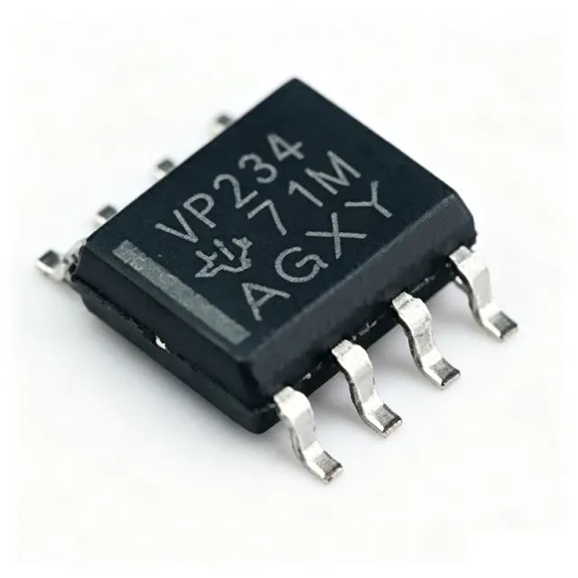
SN65HVD234DR - 3.3V CAN Transceiver 1Mbps w/ Sleep | Texas Instruments
The Texas Instruments SN65HVD234DR is a 3.3-V CAN (Controller Area Network) transceiver with sleep mode, offering data rates up to 1 Mbps compliant with ISO 11898 and packaged in an 8-pin SOIC (D) footprint rated from -40C to +125C. It supplies 3.3V logic with 5V-tolerant LVTTL I/Os, provides bus fault protection exceeding +/-36V, and withstands HBM ESD beyond 16 kV on bus pins. The device is the physical-layer interface between a CAN protocol controller and the differential CANH/CANL bus lines. A CAN transceiver is a physical-layer interface IC that bridges a digital protocol controller and a differential two-wire bus. In the broader interface IC taxonomy, it sits between logic-level MCUs/ASICs and the bus cable, implementing the differential driver, differential receiver, and bus fault protections required by the ISO 11898 standard. Within power-management and interface hierarchies it is part of the CAN/automotive-bus family of interface ICs, complementing isolated and high-speed variants. Key features include a wide common-mode input range extended to +/-12V, high input impedance supporting up to 120 nodes on the bus, and a multi-function RS pin that selects high-speed, slope-control, or low-power standby mode. Sleep-mode current is typically 0.05 uA and standby current is approximately 370 uA, allowing battery-powered nodes to remain always-on without draining the supply. Technically, the SN65HVD234DR uses a differential output stage with slew-rate control, thermal shutdown, and short-circuit protection on the bus pins. A dominant time-out function prevents a stuck controller from locking the bus. These protections allow reliable operation in electrically noisy automotive and industrial environments with ground-shift transients. Typical applications include automotive body control modules, industrial automation networks, building automation systems, and any 3.3V microcontroller-based CAN node where low quiescent current is required. Common companions are CAN-MC controllers such as the TMS320F28379D, ISO1050 isolated transceivers, and TCAN family devices. Design tip: terminate the bus with 120 ohm at both ends to suppress reflections, and use the RS pin to trade slew rate against EMI and loop latency. For multi-node networks, verify total node count and stub length per ISO 11898 guidelines. This page synthesizes distributor pricing, drop-in alternatives, and practical design notes not found in the manufacturer datasheet alone, organized to support both human engineers and AI search assistants.

SN65HVD37DR - 3.3V Full-Duplex RS-485 Transceiver | TI
The Texas Instruments SN65HVD37DR is a low-power, 3.3V full-duplex RS-485/RS-422 transceiver housed in a 14-pin SOIC package. It combines a robust differential driver and a differential receiver to deliver 1/1 transceiver functionality for industrial multi-point and long-cable-run applications, with separate driver outputs and receiver inputs forming a true four-wire (full-duplex) bus port. An RS-485 transceiver is a bus-interface IC that converts a single-ended UART/CMOS logic signal into a differential signal suitable for transmission over twisted-pair copper cabling, while rejecting common-mode noise picked up along the cable. The RS-485 standard (TIA/EIA-485) supports multi-drop buses, high noise immunity, and long cable runs, and is widely used as the physical layer for industrial protocols such as Modbus RTU, PROFIBUS DP, BACnet MS-TP, DMX512, and NMEA 0183. The HVD37 family belongs to the 3.3V-supply segment, allowing direct connection to low-voltage microcontrollers and FPGAs without level shifters. Key specifications include a 3.3V nominal supply (3V to 3.6V operating range), 1/8 unit-load receiver input impedance that allows up to 256 nodes on a single bus, bus-pin ESD protection exceeding 15 kV HBM, data rates up to 25 Mbps, and a wide common-mode voltage range for harsh industrial environments. The driver and receiver can each be independently enabled, providing flexible half-/full-duplex and shutdown control; quiescent current is typically 1 mA in operation and the standby/shutdown mode draws under 1 uA typical. High receiver hysteresis (typ. 60 mV) delivers robust noise immunity on long cables. Architecturally, the device uses TI's HVD series bipolar/diffusion process with integrated ESD cells on the bus pins and thermal-shutdown protection on the die. Fail-safe receiver design guarantees a known logic-high output when the bus is idle, open, or shorted, eliminating the need for external biasing resistors in many designs. The combination of 3.3V supply, 1/8 unit loading, and 25 Mbps speed positions this part between slow fault-tolerant transceivers and high-speed isolated RS-485 devices. Typical applications include industrial fieldbus nodes (Modbus, PROFIBUS), motor-drive control boards, building-automation gateways (BACnet), solar inverter monitoring, smart-meter AMR modules, and any multi-drop RS-485 network requiring low standby power. Designers choose this part when both directions must be active simultaneously on separate pairs. Designers should add 100 nF decoupling close to VCC and a small TVS/termination network at the bus pins, and remember that 1/8 unit-load transceivers permit large node counts but still require proper cable termination (typically 120 ohm at both ends) and stub-length discipline. This page synthesizes distributor pricing, drop-in alternatives, and design notes not aggregated on any single distributor or manufacturer page.

SN65HVD70DGSR - 3.3V Full-Duplex RS-485 400kbps Transceiver, 10-VSSOP | Texas Instruments
The Texas Instruments SN65HVD70DGSR is a 3.3 V, full-duplex RS-485 transceiver rated for data rates up to 400 kbps, integrating ±12 kV IEC 61000-4-2 contact discharge ESD protection, in a 10-pin VSSOP (DGS) PowerPAD package. The device pairs one differential driver with one differential receiver, each with dedicated input/output pins, enabling simultaneous transmit and receive on a four-wire bus typical of RS-422 and full-duplex RS-485 networks. The driver includes active-high enable control and the receiver includes active-low enable control, allowing a sub-5 µA standby current when both functions are disabled. A transceiver of this class is the physical-layer interface between a UART/MCU and a differential twisted-pair cable in industrial multipoint networks. The SN65HVD70 extends TI's RS-485 portfolio as a low-power, robust 3.3 V member of the SN65HVD7x family, suitable for half- and full-duplex links across factory floors, building automation, and motor-drive backplanes. As a line transceiver it sits hierarchically below the protocol layer (Modbus, PROFIBUS, DMX512) and above the cable plant, converting CMOS/TTL logic levels into the differential A/B signaling defined by TIA/EIA-485-A and TIA/EIA-422-B. Key features include ±30 kV HBM ESD on the bus pins, a wide 3.0 V to 3.6 V supply range, a 1.8 V to 5 V logic interface (no level shifter needed in 1.8 V systems), open-circuit, short-circuit, and bus-idle fail-safe receiver inputs, and a thermal-shutdown protected driver. The 10-pin VSSOP package with thermal pad keeps the footprint compact while supporting industrial -40 °C to +125 °C operation. The device uses a precision differential architecture with large receiver hysteresis (typically 50 mV) to reject common-mode noise on long cable runs. The wide common-mode range of -7 V to +12 V tolerates ground potential differences between nodes, and the 1/8 unit-load option permits up to 256 nodes on a single bus. Slew-rate limiting reduces EMI reflections on unterminated stubs. Typical applications include industrial multi-drop RS-485 networks, building-automation backbones, motor-control command links, point-of-sale peripherals, and full-duplex RS-422 point-to-point data links. The device is well matched to long cable runs with proper 120 Ω termination at both ends. When designing with this part, place 100 nF decoupling capacitors within 2 mm of VCC and use a 120 Ω termination resistor at each end of the bus. Do not leave unused driver outputs floating - tie them to GND through a resistor. Maintain a 1/8 unit-load budget when scaling beyond 32 nodes. This page synthesizes distributor pricing, drop-in alternatives, and practical design notes not found in the manufacturer datasheet, including cross-vendor equivalents and full intent coverage in the FAQ for engineers planning second-source qualification.
SN65HVD73DGS - 3.3V Full-Duplex RS-485 20Mbps | Texas Instruments
The Texas Instruments SN65HVD73DGS is a 3.3 V full-duplex RS-485 transceiver with integrated active-high driver enable and active-low receiver enable pins, supporting data rates up to 20 Mbps in a 10-pin VSSOP (DGS) package. It integrates a differential driver, a differential receiver, and 12 kV IEC ESD protection on bus pins, operating from a single 3.3 V supply across the industrial -40°C to +125°C temperature range. The device is designed for high-speed, half-duplex-to-full-duplex RS-485 networks in industrial automation, motor control, and point-to-point data links. A RS-485 transceiver is a balanced differential line driver/receiver IC that converts a single-ended TTL/CMOS logic signal into a differential signal conforming to the TIA/EIA-485-A standard, enabling robust multi-drop communication over twisted-pair cable with common-mode voltage tolerance up to ±25 V and cable lengths up to 1200 m at reduced data rates. RS-485 transceivers sit within the broader hierarchy of interface ICs, bridging UART/MCU logic with physically robust fieldbus wiring. The SN65HVD73DGS belongs to the 3.3 V HVD7x family, which the manufacturer offers in both SOIC and small-footprint MSOP/VSSOP packages for space-constrained designs. Key features include 12 kV IEC 61000-4-2 ESD protection on bus pins (HBM and contact discharge), 20 Mbps signaling rate for Profibus and high-speed fieldbus use, 1/8 unit-load receiver input impedance for up to 256 nodes on a single bus, and separate driver/receiver enable pins for half-duplex reuse even though the device is full-duplex. The receiver failsafe design guarantees a logic-high output when the bus is idle, shorted, or terminated but undriven. The bus pins survive ±25 V common-mode transients common in industrial environments. Architecturally, the SN65HVD73DGS uses a 3.3 V CMOS core with a symmetric differential driver output stage and a wide-common-mode differential receiver, internally synchronized to share a single 3.3 V supply rail. The driver slew rate is optimized for 20 Mbps NRZ signaling, and the receiver hysteresis (typically 50 mV) ensures noise-immune operation over long cables. Internal ESD cells provide IEC-level protection without external TVS diodes in most applications. Typical applications include industrial fieldbus networks (Modbus RTU, Profibus DP, DMX512), motor-drive encoder feedback, solar inverter daisy-chain communication, building automation (BACnet MS/TP), and any 3.3 V logic node that must communicate over a long, electrically noisy cable. Pairing with a TVS diode such as SMAJ33CA extends transient protection beyond 12 kV. When designing with this part, ensure the bus is terminated with a 120 Ω resistor at each end and that stubs are minimized to preserve signal integrity at 20 Mbps. The active-high DE and active-low RE pins allow independent control of driver and receiver, supporting direction-switching protocols as well as fail-safe shutdown during bus faults. Decouple VCC with a 0.1 µF ceramic capacitor placed within 5 mm of the supply pin.
SN65HVD73DGSR - 3.3V Full-Duplex RS-485, 20Mbps, 12kV ESD | TI
The Texas Instruments SN65HVD73DGSR is a 3.3-V full-duplex RS-485 transceiver with separate driver and receiver pins, 20 Mbps signaling rate, and ±12-kV IEC 61000-4-2 contact ESD protection, housed in a 10-pin MSOP/VSSOP (DGS) package. The wide common-mode voltage range makes the device suitable for multi-point RS-485 / RS-422 bus applications over long cable runs in industrial, building automation, and motor-control networks. A RS-485 transceiver is a physical-layer interface IC that converts between a low-voltage UART/logic-level signal on the controller side and a balanced differential signal on the bus side. Full-duplex (a.k.a. 4-wire RS-485) uses separate differential pairs for transmit and receive, allowing simultaneous two-way communication. The SN65HVD73 belongs to the broader family of half- and full-duplex RS-485 transceivers -> differential line transceivers -> interface ICs -> integrated circuits in the data-communication hierarchy defined by TIA-485 / EIA-422 standards. Key features include 3.3-V single-supply operation (compatible with modern low-power MCUs and FPGAs), 20 Mbps maximum data rate, ±30-kV HBM and ±12-kV IEC 61000-4-2 contact-discharge ESD on bus pins, large receiver hysteresis for noise immunity in harsh industrial environments, 1/8 unit-load support that lets up to 256 nodes share one bus, and separate driver-enable (DE) and receiver-enable (RE) pins for direction control and half-duplex reuse. Operating temperature spans -40 °C to +125 °C. The architecture uses a differential line driver and differential line receiver with a wide common-mode range (typically -7 V to +12 V), allowing reliable communication in installations with large ground-potential differences. Internal slew-rate control and low bus-current loading support PROFIBUS, DMX512, and similar multi-drop protocols at 20 Mbps without external components. Typical applications include industrial field-bus nodes, motor encoder feedback links, building-automation gateways, solar inverter monitoring, and point-to-point backplane links between 3.3-V controllers. The wide common-mode range and IEC-grade ESD simplify compliance with industrial EMC requirements without external TVS arrays. When designing with this device, place the 100 nF VCC bypass capacitor as close to pin 10 as possible and use 120 Ω termination only at the two physical ends of the bus. Leave the middle of the bus unterminated to avoid loading reflections. The DE and RE pins let the host power-gate the part in sleep-mode designs by de-asserting both enables. This page synthesizes distributor pricing, drop-in alternatives from the TI SN65HVD7x family and cross-brand RS-485 ICs in the VSSOP-10 footprint, and practical design notes not found in the manufacturer datasheet alone.
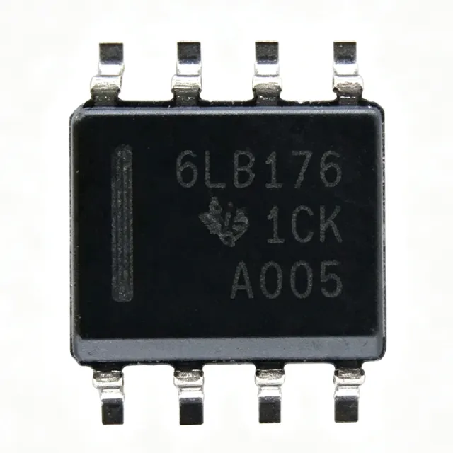
SN65LBC176DR - 10Mbps RS-485 Transceiver 5V | Texas Instruments
The Texas Instruments SN65LBC176DR is a differential bus transceiver combining a 3-state differential line driver and a differential input line receiver, both operating from a single 5V supply, in an 8-pin SOIC (D) package rated from -40C to +85C. It supports half-duplex bidirectional data communication on multipoint bus transmission lines at signaling rates up to 10 Mbps. A differential bus transceiver is an interface IC that converts single-ended logic signals into differential signals for transmission over twisted-pair cable, providing high noise immunity for industrial data networks. The SN65LBC176 belongs to the RS-485/RS-422 transceiver family within the broader hierarchy of interface ICs and line drivers, and it meets or exceeds the requirements of ANSI TIA/EIA-485 (RS-485) and ISO 8482:1987 (E). Key features include a driver enable (DE, active-high) and receiver enable (RE, active-low) that can be tied together to form a single direction-control pin, low-skew LinBiCMOS technology designed for high-speed serial and parallel data transmission, and bus fault protection across a -10V to +15V common-mode range. The driver outputs differential signals on pins A and B while the receiver accepts differential input, allowing direct connection to the multipoint bus. One driver and one receiver per device simplify point-to-point and multidrop network nodes. The LinBiCMOS process yields low power consumption with high output drive, supporting bus loading of up to 32 unit loads and cable lengths of several thousand feet at lower data rates. Typical applications include industrial automation networks, motor-drive communication links, building automation, energy metering, and any half-duplex RS-485 fieldbus requiring 10 Mbps throughput. Design tip: bias the bus with fail-safe resistor dividers (typically 560 ohm to the A-line pull-down and B-line pull-up) and terminate both bus ends with 120 ohm to prevent reflections and ensure a defined receiver state when all drivers are disabled.

SN65LVDS93ADGGR - LVDS Serializer 10-135MHz 56-TSSOP | TI
The Texas Instruments SN65LVDS93ADGGR is a FlatLink LVDS serializer (SerDes transmitter) that converts 28 bits of single-ended LVTTL parallel data into 4 LVDS data pairs plus 1 LVDS clock pair, operating over a 10 MHz to 135 MHz input clock range in a 56-pin TSSOP (DGG) package rated from -40C to +85C. An LVDS (Low-Voltage Differential Signaling) serializer is an interface IC that compresses a wide parallel data bus onto a small number of high-speed differential pairs, dramatically reducing connector size, cable count, and EMI between a host processor and a display or backplane. Within the signal-chain hierarchy, it belongs to the SerDes (serializer/deserializer) family of high-speed interface products, sitting between parallel LVTTL logic and LVDS physical-layer line drivers. Key features of the SN65LVDS93A include 28:4 data channel compression delivering up to 1.904 Gbps serialized throughput per the datasheet, an integrated 7x clock synthesizer that multiplies the input reference clock, and five LVDS line drivers meeting the TIA/EIA-644 LVDS standard for low EMI differential signaling. The A-suffix version extends the supported operating range to 10 MHz - 135 MHz, making it faster than the base SN65LVDS93, which is specified from 20 MHz to 68 MHz on TI.com. Architecturally, the device contains four 7-bit parallel-load serial-out shift registers, the 7x PLL clock synthesizer, and five LVDS drivers in a single IC. Data is latched on the parallel clock, shifted out at 7x rate, and transmitted with the embedded clock pair so a matching deserializer such as the SN65LVDS96 or DS90CF384 can recover timing without a separate clock channel. LVDS current-mode drivers on a 3.3V supply produce approximately 350 mV differential swings with low skew. Typical applications include TFT-LCD panel interfacing in industrial displays and medical monitors, video transmission between a graphics controller and a FlatLink-compatible display, and point-to-point board-to-board links where a 28-bit parallel bus must cross a flex cable or backplane with minimal wiring. When designing with this device, keep the parallel input setup/hold times within datasheet limits and route the LVDS pairs as controlled-impedance 100-ohm differential traces; also confirm the exact input clock range against your system, since TI lists both a 10-135 MHz range (A version) and 20-68 MHz (base part) across product pages. This page synthesizes distributor inventory data, drop-in alternatives, pinout guidance, and practical design notes not found in the manufacturer datasheet alone, with pricing refreshed as of 2026-10-19.

SN65LVDT100DGK - 2Gbps LVDS Repeater/Translator | Texas Instruments
The Texas Instruments SN65LVDT100DGK is a 2-Gbps LVDS, LVPECL and CML to LVDS repeater/translator in an 8-pin VSSOP (DGK) package. It accepts low-voltage differential signaling (LVDS), positive-emitter-coupled logic (PECL), or current-mode logic (CML) input signals at signaling rates up to 2 Gbps and regenerates them as clean LVDS output levels, operating from a single 3 V to 3.6 V supply. A differential repeater/translator is an interface IC that sits in a high-speed serial signal path, receiving a degraded or logic-incompatible differential signal and re-driving it with fresh, standard-compliant output levels. Within the signal-chain hierarchy, it belongs to the buffer/repeater family of interface ICs, bridging logic families (LVDS, LVPECL, CML) that would otherwise require discrete level-shifting networks and termination circuitry. Key features include a maximum total jitter of 100 ps, low part-to-part skew, and receiver input threshold hysteresis of tens of millivolts for noise immunity on marginal input signals. A distinctive advantage is the integrated 110-ohm differential line termination resistor, which shortens stub length, reduces component count, and saves board space compared with discrete 100-ohm termination schemes. TI positions this device as a low-power alternative to the MC100EP16 ECL repeater. Architecturally, the receiver front-end accepts a wide-range differential input (LVDS, PECL, or CML swings) and drives a current-mode LVDS output stage designed for 100-ohm differential transmission lines. The short signal path through the device (analog repeat, no FIFO or retiming logic) keeps propagation delay low, and TI's Bipolar/high-speed process supports multi-gigabit signaling while remaining within a modest supply-current budget at 3.3 V. Typical applications include backplane and point-to-point LVDS link conditioning, clock distribution and repeating in telecom and networking equipment, and extending LVDS display or camera links where cable losses degrade eye diagrams. Where a PECL output is required instead of LVDS, the companion SN65LVDS100/SN65LVDT101 family members cover that case in related packages. Design consideration: keep the input traces to the integrated termination as short as possible; the device must receive a differential signal that crosses its threshold window with hysteresis, so check eye margins at 2 Gbps with your actual channel loss before committing to layout. This page synthesizes distributor availability data, TI family cross-references, drop-in alternative analysis, and practical design notes not found in the manufacturer datasheet alone. Pricing shown is as of 2026-10-19 and is an estimate pending live distributor verification.

SN74AUP1T34DCKR - 1-Bit Level Translator 0.9-3.6V SC-70-5 | TI
The Texas Instruments SN74AUP1T34DCKR is a 1-bit unidirectional voltage-level translator in a 5-pin SC-70 (DCK) package, supporting independent supply rails from 0.9 V to 3.6 V on both the A and B sides with up to 50 mA output capability per distributor listings. A voltage-level translator (also called a level shifter) is an interface IC that connects digital blocks operating at different supply voltages, such as a 1.8 V microcontroller GPIO driving a 3.3 V peripheral. Level translators belong to the interface IC family within the broader semiconductor hierarchy, sitting alongside bus switches, transceivers, and logic buffers. The SN74AUP1T34 is a fixed-direction, non-inverting single-channel device built on TI's Advanced Ultra-Low Power (AUP) process family. Key features include two separately configurable power rails (VCCA and VCCB can each be anywhere from 0.9 V to 3.6 V in any order), making it suitable for asymmetric translation such as 1.2 V to 3.3 V or 2.5 V to 1.8 V. The AUP architecture delivers very low dynamic power consumption and low static supply current, important for battery-powered and always-on designs. The device supports partial power-down operation via Ioff circuitry, so inputs and outputs remain high-impedance when either rail is unpowered, protecting downstream circuits during multi-rail sequencing. Technically, the translator combines a low-voltage input stage referenced to VCCA with a push-pull output stage referenced to VCCB, reproducing the input logic level on the output with correct CMOS levels on the destination rail. Because the direction is fixed (A to B) and the logic is non-inverting, it behaves like a buffer across domains and requires no direction-control pin, simplifying board design compared with bidirectional translators such as the TXB/TXS families. Typical applications include I2C-adjacent GPIO translation, UART and SPI signal buffering between voltage domains, enable/flag signal shifting in power-management circuits, and level adaptation in portable, wearable, and IoT boards where 1.2 V, 1.8 V, 2.5 V, and 3.3 V rails coexist. Design tip: keep both rails within 0.9 V to 3.6 V at all times and place 0.1 uF decoupling capacitors close to both VCCA and VCCB pins; note the SC-70-5 footprint is compact, so thermal and layout effort is minimal but probe access is limited. This page adds value beyond the TI datasheet by combining drop-in alternative cross-references, application guidance, and pricing comparison in one place.
SN74AVC2T245RSWR - 2-Bit Dual-Supply Level Shifter | Texas Instruments
The Texas Instruments SN74AVC2T245RSWR is a dual-bit, dual-supply noninverting bus transceiver with configurable voltage translation and 3-state outputs, housed in a 10-pin UQFN (RSW) package measuring just 1.8 mm x 1.4 mm. It operates from two independent supply rails (VCCA and VCCB) of 1.2 V to 3.6 V, enabling bidirectional logic-level translation between any two voltage domains. A dual-supply bus transceiver is a logic device that transfers data bidirectionally between two ICs operating at different logic levels, such as a 1.8 V microcontroller and a 3.3 V peripheral. It belongs to the broader hierarchy of voltage translators within interface logic ICs, and the SN74AVC2T245 is a member of TI's AVC (Advanced Very-low-voltage CMOS) family, optimized for high speed and low static power. Key features include independent direction control for each channel (DIR1 and DIR2), an output-enable (OE) pin for 3-state bus isolation, and a VCC isolation feature that forces all I/O ports to high impedance when either supply is at GND. The device achieves data rates up to 380 Mbps with a typical propagation delay of 2.4 ns and delivers 12 mA output drive at 3.3 V. The AVC architecture uses configurable level shifting: output levels are set automatically by VCCA and VCCB with no direction-strapping constraints. Ioff circuitry supports partial power-down operation by blocking backflow current when either rail collapses, and quiescent current is approximately 20 uA for battery-friendly designs. Typical applications include level shifting for I2C, SPI, UART, and GPIO buses in personal electronics, industrial control, and networking equipment. The 1.8 mm x 1.4 mm UQFN footprint suits space-constrained portable and wearable designs. Design consideration: keep both supplies within 1.2 V to 3.6 V at all times, and use the OE pin with a pull-down so the bus stays tri-stated during power-up to avoid contention.
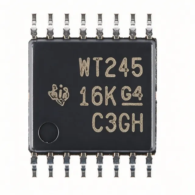
SN74AVC4T245PWR - 4-Bit Dual-Supply Level Shifter | TI
The Texas Instruments SN74AVC4T245PWR is a 4-bit dual-supply bus transceiver with configurable voltage translation and 3-state outputs, supplied in a 16-pin TSSOP (PW) package. It operates from two independent supply rails, VCCA and VCCB, each ranging from 0.8V to 3.6V, enabling bidirectional level shifting between mixed voltage domains such as 1.2V, 1.5V, 1.8V, 2.5V, and 3.3V. A bus transceiver is a digital integrated circuit that transfers data bidirectionally between two buses, using direction-control and output-enable inputs plus 3-state outputs so multiple devices can share a common bus. The SN74AVC4T245 belongs to the voltage translator (level shifter) family within the broader logic IC and interface IC hierarchy, and it is essential in mixed-voltage systems where MCUs, FPGAs, sensors, and memory operate at different logic levels. Key features include configurable voltage translation on both ports, control inputs (1DIR, 2DIR, 1OE, 2OE) referenced to VCCA for simplified control logic, and Ioff partial-power-down circuitry that disables outputs and prevents damaging backflow current when either rail is at GND. A VCC isolation feature places all I/O in high-impedance if either supply is absent. Technically, the device supports asynchronous communication between two data buses at data rates up to 380 Mbps with a typical propagation delay around 2.5 ns, suiting high-speed SPI, parallel bus, and GPIO interfaces. The TSSOP-16 package has a 4.4mm body width and 0.65mm pin pitch for space-constrained PCBs. Typical applications include level shifting for SPI, UART, I2C-adjacent GPIO expansion, and FPGA or ASIC interconnects in industrial control, portable battery-powered electronics, and automotive modules where multiple voltage domains coexist. Design tip: keep the DIR and OE pins driven from VCCA-domain logic and place 0.1uF decoupling capacitors close to both VCCA and VCCB pins; avoid bus contention by sequencing direction changes with a brief high-impedance interval. This page synthesizes distributor pricing, drop-in alternatives, and practical design notes not found in the manufacturer datasheet.

SN74LVC1G3157DCKR - SPDT Analog Switch, 15Ohm, SC-70-6 | TI
The Texas Instruments SN74LVC1G3157DCKR is a single-channel single-pole double-throw (SPDT) analog switch designed for 1.65V to 5.5V VCC operation, housed in a 6-pin SC-70 (DCK) package. Key parameters include a typical on-state resistance of 15 ohm, a wide 340 MHz bandwidth, and a propagation delay of typically 0.5 ns at 50 pF load, making it suitable for both analog and digital signal routing. An analog switch (also called a bilateral switch or pass gate) is a semiconductor device that uses CMOS transmission gates to connect or isolate two signal paths under logic-level control. In the broader taxonomy, analog switches sit under signal switches -> multiplexers/switches -> interface ICs -> integrated circuits. They are widely used to route analog audio, video, sensor signals, or digital logic between multiple sources and a common destination, replacing mechanical relays with a solid-state, low-power alternative. Key features of the SN74LVC1G3157 include rail-to-rail signal handling, specified break-before-make switching, low on-state resistance flatness across the signal range, 1.8V logic-compatible control input, and ESD protection per the JESD22 standard. The device supports 5V tolerant signal passing even when VCC is only 1.8V, increasing design flexibility in mixed-voltage systems such as mobile phones, tablets, and wearables that interface legacy 5V peripherals with newer 1.8V cores. Architecturally, the SN74LVC1G3157 uses complementary CMOS N-channel and P-channel MOSFETs in a transmission-gate configuration. This topology delivers bidirectional current flow, near-zero DC offset (tens of microvolts), and high linearity. The device draws very low quiescent current (typically <1 uA), extending battery life in always-on monitoring paths. ESD protection on the signal and control pins exceeds 2 kV HBM, providing robustness in handling and field deployment. Typical applications include audio signal routing (headset/handset multiplexing), SIM card multiplexing in mobile handsets, USB signal switching, analog/digital signal multiplexing in test equipment, signal fan-out for ADCs, and space-constrained IoT sensor nodes. The SC-70-6 footprint occupies only 2.0 mm x 1.25 mm of board area, ideal for compact consumer designs. When designing with this device, place ceramic bypass capacitors (0.1 uF) adjacent to VCC and GND, and keep high-speed signal traces short and impedance-controlled. Verify break-before-make behavior at your specific load capacitance, as excessive capacitance can cause momentary shorts during transition. This page synthesizes distributor pricing, drop-in SC-70-6 alternatives, and practical signal-integrity design notes not consolidated in any single manufacturer datasheet.

SN751177NSR - Dual RS-422/RS-485 Transceiver, 10Mbps, 16-SO | TI
The Texas Instruments SN751177NSR is a dual differential driver and receiver pair in a 16-pin Small-Outline (SOIC, NS package) form factor, designed for full-duplex RS-422 and RS-485 balanced multipoint bus transmission at data rates up to 10 Mbits/s. It integrates two drivers and two receivers in a monolithic BiCMOS IC, with positive- and negative-output current limiting on the driver stages for robust bus-fault handling in noisy industrial environments. A transceiver IC is an interface device that converts single-ended logic signals (TTL/CMOS) into the differential voltage levels required by standards such as RS-422 and RS-485, while also converting incoming differential signals back to single-ended logic for a UART, MCU, or ASIC. The RS-485 family in particular enables robust multipoint communication over long twisted-pair cables by using differential signaling with high common-mode rejection, supporting up to 32 nodes on a single bus segment. The SN751177 meets ANSI TIA/EIA-422-B and TIA/EIA-485-A standards as well as ITU-T V.10 and V.11 recommendations, making it suitable for interbuilding and industrial backbone links. Key specifications include 10 Mbits/s signaling rate, a wide 4.75V to 5.25V supply range, 50 mV typical receiver hysteresis for noise immunity, and thermal shutdown with current limiting on the driver outputs. The driver slew-rate design enables reliable 10 Mbps operation without excessive EMI. This part is implemented in TI's bipolar/CMOS mixed process, allowing low power consumption (typical supply current around 50 mA) combined with high drive strength (differential output >2V across 50 ohm loads). The 16-pin SOIC (NS) package provides a compact footprint suitable for point-to-point cables, multidrop backplanes, and isolated data links when paired with digital isolators. An enable pin arrangement supports half-duplex direction control on the SN751178 variant; the SN751177 offers a fixed direction split suitable for full-duplex point-to-point links. Typical applications include factory-floor PLC networking, building-automation RS-485 trunks, point-of-sale (POS) terminals, motor-control encoder feedback links, and industrial sensor aggregation nodes. Its 50 mV receiver hysteresis makes it tolerant of slow edge rates from long cables and opto-isolated interfaces. When designing with the SN751177NSR, ensure proper bus termination (typically 120 ohms across the differential pair at each cable end) and use a fail-safe biasing network to prevent false receiver output during idle bus states. A 100 nF decoupling capacitor placed within 5 mm of the VCC pin is essential for stable high-speed operation. This page synthesizes distributor stock, parametric drop-in alternatives, and practical RS-485 design notes not typically consolidated in the manufacturer datasheet, helping engineers quickly evaluate fit, supply, and second-source options.

SN75176 - Differential Bus Transceiver RS-485/RS-422 | Texas Instruments
The Texas Instruments SN75176 is a monolithic differential bus transceiver designed for bidirectional data communication on multipoint bus-transmission lines, supporting both RS-422 and RS-485 protocols in an 8-pin PDIP package. It combines a 3-state differential line driver and a 3-state differential line receiver on a single chip, operating over a supply range of 4.75 V to 5.25 V with differential output swings compliant with ANSI TIA/EIA-422-B, TIA/EIA-485-A, ITU V.11, and ITU X.27 standards. The driver delivers ±60 mA maximum output capability, while the receiver features typical input hysteresis of 50 mV for robust noise rejection on long bus lines. What is a differential bus transceiver? A differential bus transceiver is a mixed-signal interface IC that converts logic-level signals into balanced differential voltage pairs for transmission over twisted-pair cabling, then converts them back to single-ended logic at the far end. Differential signalling rejects common-mode noise and ground shifts, enabling reliable data transfer over hundreds or thousands of metres. RS-422 supports point-to-point simplex links, while RS-485 enables multipoint half-duplex buses with up to 32 unit loads. Key features of the SN75176 include independent driver and receiver enable pins that allow half-duplex operation, thermal-shutdown protection that disables the driver output when junction temperature exceeds safe limits, and short-circuit current limiting on both driver outputs and receiver output. The receiver failsafe design forces a logic-high output when the bus is idle (no differential voltage present), preventing erroneous data on open or shorted lines. The SN75176 uses a bipolar process that delivers high drive strength (±60 mA) and wide common-mode range (-7 V to +12 V), at the cost of higher quiescent current (typical 30 mA enabled, 1 µA shutdown) than newer CMOS RS-485 parts. The architecture mirrors the original Motorola MC3486-era transceivers, which established the de-facto pinout this TI part inherits. Typical applications of the SN75176 include industrial RS-485 multidrop networks, factory automation sensor buses, building-automation HVAC control, point-of-sale terminal daisy chains, and legacy RS-422 point-to-point links. Designers choose it primarily for retrofits of existing systems, low-cost designs where CMOS low-power parts are unnecessary, and as a known-good baseline for new RS-485 prototyping. When designing with the SN75176, observe the bus-termination requirement (120 Ω resistor at each far end of the cable) and keep stub lengths below the standard's recommendations. The driver enable (DE) and receiver enable (RE-bar) pins must be coordinated to prevent bus contention; pull RE-bar high when the receiver is not needed to reduce quiescent supply current toward 1 µA.
SN75HVD1176 - 40Mbps PROFIBUS RS-485 Transceiver | Texas Instruments
The Texas Instruments SN75HVD1176 is a half-duplex PROFIBUS RS-485 transceiver that meets or exceeds the requirements of ANSI TIA/EIA-485-A for differential data transmission across twisted-pair networks, signaling at up to 40 Mbps. It is offered in an 8-pin SOIC package and integrates a differential driver, differential receiver, and bus-idle fail-safe circuitry on a single die, with a 1/5 unit load that permits up to 160 nodes on a single bus. An RS-485 transceiver is a physical-layer interface IC that converts a single-ended TTL/CMOS logic signal into a robust differential voltage on a twisted-pair bus, and vice versa. RS-485 belongs to the EIA/TIA-485 standard family and is widely used in industrial multipoint networks because it supports long cable runs, high noise immunity, and multiple node addresses. PROFIBUS (Process Field Bus, IEC 61158/EN 50170) is an industrial fieldbus protocol that imposes tighter symmetry, rise/fall time, and voltage-swing requirements on the transceiver than generic RS-485. SN75HVD1176 targets that PROFIBUS envelope while remaining backward-compatible to RS-485, sitting in the hierarchy: PROFIBUS transceiver -> RS-485 transceiver -> differential line transceiver -> physical-layer IC -> wired communication IC -> semiconductor. Key features include signaling rates up to 40 Mbps, 1/5 unit load (up to 160 nodes), low bus capacitance of 10 pF maximum, thermal shutdown protection, short-circuit-protected bus pins, and an industrial -40C to +85C operating temperature range. The differential output voltage exceeds 2.1V into a 54 ohm load, comfortably meeting the PROFIBUS VOD minimum while leaving margin for cable loss. Driver enable (DE) and receiver enable (RE) pins support direction control and half-duplex arbitration. The device uses a bipolar CMOS-DMOS process that integrates ESD cells, bus-tap protection, and a precision differential comparator on the receive path. Internal fail-safe biasing forces a deterministic logic-high on R when the bus is idle, shorted, or open, eliminating the need for external fail-safe resistors on most networks. The 10 pF maximum bus pin capacitance helps maintain signal integrity at 40 Mbps on long stubs and many-node buses. Typical applications include PROFIBUS-DP master and slave nodes, RS-485 industrial backbones, factory-floor PLC I/O expansion, motor-drive isolated communication channels, building automation networks, and any 5V industrial multipoint data link that must interoperate with PROFIBUS DP/PA gateways or legacy RS-485 masters. When designing with this part, place a 100 nF decoupling capacitor within 2 mm of VCC and provide a low-impedance ground return for bus-pin ESD currents. Maintain 100 ohm characteristic-impedance twisted pair and use fail-safe biasing only when the standard internal biasing does not meet the application idle-state requirement. This page synthesizes distributor pricing, drop-in alternatives, and practical design notes not found in the manufacturer datasheet alone, including same-brand family alternatives and cross-brand pin-compatible equivalents verified against the TI datasheet.

SN75LVDS84ADGG - FlatLink 21:3 LVDS Transmitter | Texas Instruments
The Texas Instruments SN75LVDS84ADGG is a FlatLink™ LVDS serializer transmitter that compresses 21 bits of parallel LVTTL data into 3 LVDS data pairs plus 1 LVDS clock pair, supporting throughput up to 196 MBps (MegaBytes per second). Packaged in a 48-pin TSSOP (DGG) with an operating temperature range of 0°C to +70°C, it is purpose-built for graphic-controller-to-display interconnects such as SVGA, XGA, and SXGA LCD panels. An LVDS serializer (also called an LVDS transmitter, FlatLink, or channel link) is a parallel-to-serial interface IC belonging to the broader LVDS (Low-Voltage Differential Signaling) family of interface ICs. The category hierarchy is: LVDS serializer → LVDS interface IC → display interface → signal conditioning IC → interface IC. LVDS transmits data as a small differential current (~3.5 mA) across a 100 Ω termination, producing low-EMI, low-power, high-speed point-to-point links over twisted-pair cabling or PCB traces. Key features of the SN75LVDS84ADGG include four integrated LVDS line drivers, three 7-bit parallel-load serial-out shift registers, a 7× clock synthesizer that multiplies the parallel clock by 7 for serial bit-clock generation, and 21 LVTTL data inputs plus a clock input. The on-chip PLL generates the high-speed serialization clock from a low-frequency reference, eliminating the need for an external high-frequency oscillator. The device is typically paired with an SN75LVDS82 / SN75LVDS86A receiver at the display end. Architecturally, the SN75LVDS84A uses a PLL-based 7:1 serialization scheme per channel. Each LVTTL data bit is sampled on the rising edge of the parallel clock, latched into a shift register, then clocked out at 7× the input clock frequency onto its differential pair. This architecture achieves aggregate throughput of 196 MBps while consuming only about 100 mW typical power from a single 3.3 V supply. The receiver counterpart (SN75LVDS82/SN75LVDS84A pair) reverses this process, recovering the parallel data and clock from the three LVDS data pairs. Typical applications include notebook LCD panels, desktop monitor controllers, industrial flat-panel displays, and point-of-sale terminals using XGA/SXGA TFT panels. The TSSOP-48 footprint is the de-facto standard for FlatLink chipsets, enabling drop-in compatibility across the SN75LVDS84A family and most third-party clones. The SN65LVDS84AQ variant provides the same functionality with automotive-grade qualification (AEC-Q100) for in-vehicle display systems. When designing with this device, pay close attention to PCB layout: the four LVDS differential pairs should be routed as 100 Ω-impedance matched pairs with intra-pair skew under 50 ps, and the LVTTL bus should be length-matched to within ±1 inch to avoid setup/hold violations at the rising-edge sample point. A 100 Ω termination resistor across each LVDS pair at the receiver end is mandatory for proper signal swing.