IRF7389PBF vs IRF7854TRPBF Comparación
Comparación detallada lado a lado de IRF7389PBF por Infineon y IRF7854TRPBF por Infineon. Compare las especificaciones clave, los parámetros eléctricos, el encapsulado, el estado del ciclo de vida, los precios y la disponibilidad para determinar el mejor componente para los requisitos de su diseño.

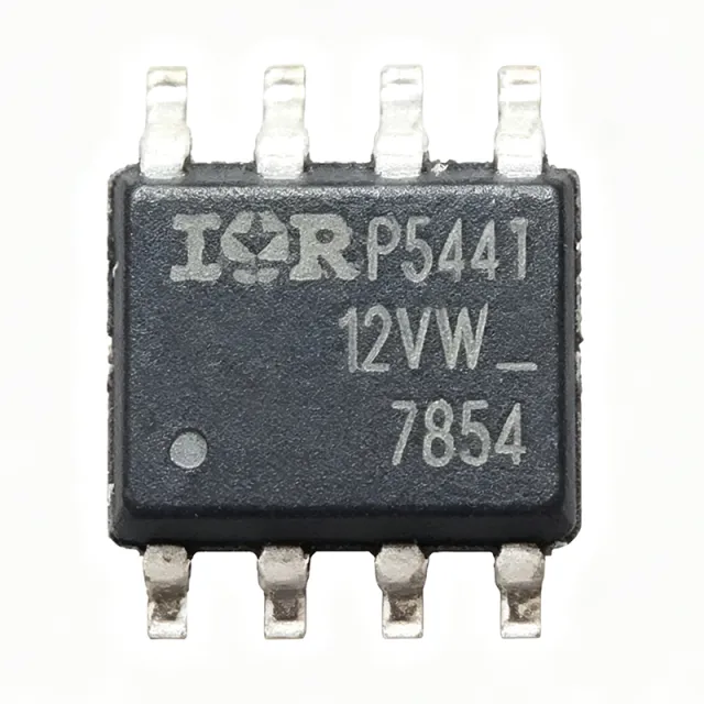
Comparación de especificaciones
| Parámetro | IRF7389PBF | IRF7854TRPBF |
|---|---|---|
| Marca | Infineon | Infineon |
| Categoría | MOSFETs | MOSFETs |
| Estado del ciclo de vida | Activo | Activo |
| Estado del stock | In Stock | In Stock |
| Precio unitario (USD) | $0,61 | $0,48 |
| Configuration | N and P-Channel (complementary half-bridge) | — |
| Drain-to-Source Voltage N-Ch (V_DSS) | 30 V | — |
| Drain-to-Source Voltage P-Ch (V_DSS) | -30 V | — |
| Continuous Drain Current N-Ch (I_D) | 7.3 A | — |
| Continuous Drain Current P-Ch (I_D) | -5.3 A | — |
| On-Resistance N-Ch R_DS(on) max | 0.029 ohm at V_GS=10V | — |
| On-Resistance P-Ch R_DS(on) max | 0.058 ohm at V_GS=10V | — |
| Total Gate Charge N-Ch (Q_g) typical | 22 nC | — |
| Total Gate Charge P-Ch (Q_g) typical | 23 nC | — |
| Power Dissipation (P_D) | 2.5 W | — |
| Technology | Generation V HEXFET | HEXFET (planar N-channel) |
| Encapsulado | SO-8 (SOIC-8) surface mount | SO-8 |
| Pinout | Industry-standard complementary SO-8 | — |
| Rango de temperatura de funcionamiento | [DATA_NEEDED: full operating temperature range] | -55°C to +150°C (TJ) |
| Tipo de montaje | Surface Mount | Surface Mount |
| Estado RoHS | Compliant | — |
| Lead-Free | Yes | — |
| Sin halógenos | Yes | — |
| Avalanche Rated | Yes (fully avalanche rated) | — |
| FET Type | — | N-Channel |
| Drain-Source Voltage (VDS) | — | 80 V |
| Continuous Drain Current (ID) at Ta=25°C | — | 10 A |
| Power Dissipation (PD) at Ta=25°C | — | 2.5 W |
| On-Resistance RDS(on) max at VGS=10V | — | 13.4 mΩ |
| Gate-Source Threshold Voltage VGS(th) max | — | 4.9 V |
| Total Gate Charge Qg | — | 27 nC |
| Lead-Free / RoHS | — | Yes (PBF suffix, lead-free) |
| Qualification | — | JEDEC industrial, Normal level |
| Solder Process | — | Reflow and wave-solderable |
| Gate Drive Voltage (recommended) | — | 10 V |