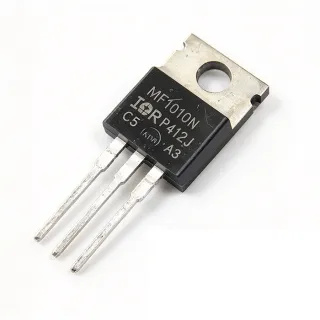
IRF1010EPBF - 60V 84A N-Channel Power MOSFET | Infineon
N.º de pieza: IRF1010EPBF ✓ Activo| Cant. | Precio unitario | Total |
|---|---|---|
| 1 | $0.55 | $0,55 |
| 10 | $0.52 | $5,20 |
| 100 | $0.5021 | $50,21 |
| 500 | $0.48 | $240,00 |
| 1.000 | $0.45 | $450,00 |
IRF1010EPBF Descripción general
A power MOSFET is a voltage-controlled semiconductor switch used to regulate or switch electrical power in a circuit. Within the component hierarchy, it sits under the transistor family, alongside IGBTs and BJTs, and forms the core switching element in power management systems such as DC-DC converters, motor drives, and switching power supplies. The TO-220AB package is universally preferred for commercial and industrial applications at power dissipation levels up to approximately 50 watts, according to Infineon datasheet documentation.
Key features include an advanced HEXFET silicon process from International Rectifier (now part of Infineon Technologies) that achieves extremely low on-resistance per unit silicon area, high continuous current handling of 84 A at a case temperature, and the RoHS3-compliant lead-free PBF suffix construction. The low 12 milliohm on-resistance minimizes conduction losses, while the 86.6 nC gate charge reduces gate-drive power requirements in switching converters.
The HEXFET architecture uses advanced processing techniques with a low thermal-resistance die attach, enabling the device to withstand high pulsed currents typical of inrush and short-circuit events. The standard-level gate threshold makes it directly drivable from gate-driver ICs and controller outputs in hard-switching topologies.
Typical applications include DC motor control, inverters, switched-mode power supplies (SMPS), lighting systems, load switches, and battery-powered equipment, all application areas explicitly listed in the manufacturer product description.
A key design consideration is thermal management: because the 84 A and 200 W ratings apply at a case temperature of 25 C, designers must compute real dissipation as I2 x RDS(on) and provide adequate heatsinking, since through-hole TO-220 thermal performance depends heavily on copper pad area.
This page adds value beyond the datasheet by synthesizing distributor pricing (LCSC from $0.5021), drop-in alternative analysis, and practical design notes not found in the manufacturer documentation. Pricing and availability data referenced as of 2026-10-20.
Alternativas directas para IRF1010EPBF — mismo encapsulado, compatible pin a pin. Se excluyen las piezas de otro encapsulado que requieren retrabajo de la PCB.
Variantes de esta serie
Modelos de la misma serie compatibles directamente con IRF1010EPBF (mismo factor de forma y huella) — difiere en Package, Drain-Source Voltage (VDS), Technology, RoHS Status.
Herramienta de comparación rápida — seleccione piezas alternativas para compararlas lado a lado:
IRF1010EZPBF
✅ Sustitución directa📋 Alternativa de referencia (no en el catálogo)
IRF1407PBF
✅ Sustitución directa✓ En stock
$0.86 / unidad
Ver hoja de datos →IRF2807Z
✅ Sustitución directa📋 Alternativa de referencia (no en el catálogo)
IRFB3206
✅ Sustitución directa📋 Alternativa de referencia (no en el catálogo)
IRFB3077
✅ Sustitución directa📋 Alternativa de referencia (no en el catálogo)
IRFB4110PBF
✅ Sustitución directa✓ En stock
$1.55 / unidad
Ver hoja de datos →IRF1010EPBF Valores máximos y características eléctricas
| Polarity | N-Channel |
| Drain-Source Voltage (VDS) | 60 V |
| Continuous Drain Current (ID) | 84 A at Tc |
| Power Dissipation (PD) | 200 W at Tc |
| On-Resistance (RDS(on)) | 12 mOhm |
| Total Gate Charge (Qg) | 86.6 nC |
| Technology | HEXFET Power MOSFET |
| Encapsulado | TO-220AB |
| Tipo de montaje | Through Hole |
| Configuration | Single FET |
| Estado RoHS | RoHS3 Compliant |
| Nivel MSL | 3 (168 Hours) |
Configuración de pines de IRF1010EPBF
| Pin 1 | Gate — Gate control terminal; drive with 10 V for full enhancement |
| Pin 2 | Drain — Drain terminal; electrically connected to the metal tab/case |
| Pin 3 | Source — Source terminal; reference for gate drive and current return |
Área de funcionamiento seguro (estimated from rated limits)
Aplicaciones típicas
IRF1010EPBF es adecuado para 6 aplicacións: DC Motor Control, Switch-Mode Power Supplies (SMPS), Inverters, Load Switches and Hot-Swap, Lighting Systems, Battery-Powered Equipment.
DC Motor Control
The IRF1010EPBF fits DC motor drives because its 84 A (Tc) continuous rating and 12 milliohm on-resistance absorb the high inrush and stall currents that motors demand at startup, while the 60 V breakdown provides ample margin over 12 V and 24 V bus systems. In H-bridge or half-bridge PWM topologies, the device is placed as the low-side or high-side switch with a gate driver between the controller and the gate pin. The 86.6 nC total gate charge defines the driver current needed at the target PWM frequency; at 20 kHz with a 1 A driver, estimated switching transition times stay in the sub-microsecond range. Thermal design is the limiting consideration - estimated conduction loss at a 20 A motor run current is about 4.8 W, so the TO-220AB tab must be bolted to a heatsink, and freewheeling diodes or synchronous rectification should handle inductive kickback.
Recomendado
Switch-Mode Power Supplies (SMPS)
In offline and DC-DC switch-mode power supplies, the IRF1010EPBF serves as the primary or secondary switching element where its 60 V rating covers 24 V-48 V bus rails and its 12 milliohm on-resistance keeps conduction losses low in continuous-conduction flyback, forward, and push-pull stages. Infineon explicitly lists SMPS among the target applications for the IRF MOSFET family. The 86.6 nC gate charge drives the choice of PWM controller gate-drive strength; at 100 kHz switching, estimated gate-drive power is Qg x Vgs x fsw, roughly 0.1 W per device at 10 V drive. The through-hole TO-220AB package simplifies thermal design in industrial PSUs, allowing direct heatsink mounting with isolation pads. Designers should verify avalanche energy ratings if the topology relies on leakage-inductance clamping through the MOSFET body rather than a snubber or RCD clamp.
Recomendado
Inverters
Power inverters - including DC-AC inverter stages and low-voltage uninterruptible supplies - use the IRF1010EPBF in push-pull or full-bridge configurations where its 60 V blocking voltage suits 12 V, 24 V, and 48 V battery-fed buses. The manufacturer application list names inverters directly for the IRF MOSFET family. In a full bridge, four devices switch alternately under PWM control; conduction loss per device at 15 A RMS is estimated at 15^2 x 0.012 = 2.7 W, and parallel devices can be used to split current since the positive temperature coefficient of RDS(on) aids current sharing. The low on-resistance per silicon area achieved by the HEXFET process keeps efficiency high across the load range, while the through-hole package withstands the mechanical vibration and thermal cycling common in inverter enclosures. Dead-time management and gate resistors should be tuned to limit shoot-through losses.
Recomendado
Load Switches and Hot-Swap
As a load switch, the IRF1010EPBF disconnects high-current rails in battery-powered and industrial equipment, an application class Infineon lists explicitly. Its 12 milliohm on-resistance yields only 0.24 W estimated dissipation at a 10 A continuous load, minimizing voltage drop (120 mV) and wasted power in the conduction path. Because the part is a standard-gate-level HEXFET, it is driven with 10 V gate drive for full enhancement; a small NPN or logic-level driver plus pull-down resistor prevents floating-gate partial turn-on during startup. The TO-220AB through-hole format suits panel-mounted or serviceable power distribution boards where field replacement matters. Designers should add a gate-source resistor, control inrush with a soft-start on the gate RC, and verify the 60 V rating against inductive load transients with a TVS clamp if necessary.
Recomendado
Lighting Systems
High-current LED drivers and HID ballasts employ the IRF1010EPBF as the switching transistor in buck or buck-boost constant-current stages; lighting is another application domain named in the Infineon product description. The 60 V rating covers automotive 12 V and industrial 24 V LED string supplies with margin, and the low 12 milliohm on-resistance keeps efficiency high so that lamp luminous efficacy is not eroded by switch losses - at 8 A LED current, estimated conduction loss is only about 0.77 W per cycle of conduction. The 86.6 nC gate charge is manageable by standard lighting PWM controllers at 100-300 kHz, and the TO-220AB package mounts to the luminaire heatsink directly, reusing the housing's thermal path. Synchronization of PWM dimming with the switch node should avoid audible-band frequencies to eliminate flicker and acoustic noise.
Recomendado
Battery-Powered Equipment
Battery-powered systems such as portable welders, e-mobility packs, and robotics platforms use the IRF1010EPBF for battery disconnect, pre-charge, and motor-drive switching. Infineon lists battery-powered applications among the target uses of the IRF MOSFET family. Its 60 V class supports 4-series to 10-series lithium-ion stacks with transient headroom, and the 84 A (Tc) rating covers peak discharge demands that battery packs deliver during acceleration or weld pulses. Because conduction loss dominates in these applications, the 12 milliohm RDS(on) preserves runtime; estimated loss at 25 A discharge is about 7.5 W, so parallel MOSFETs or forced-air cooling is recommended for sustained discharge. The through-hole TO-220AB construction tolerates the vibration and high-current busbar soldering typical of battery assemblies, and the source-kelvin connection layout should minimize parasitic gate-loop inductance for clean switching.
Recomendado
Resumen de productos recomendados
Datos de referencia de ingeniería para IRF1010EPBF — comparación, orientación de diseño e información de cumplimiento.
Guía de selección
Comparación con alternativas
| Parámetro | Este producto | IRF1010EZPBF | IRF1407 | IRFB3206 | IRFB4110 |
|---|---|---|---|---|---|
| Package | TO-220AB | TO-220AB - same | TO-220AB - same | TO-220AB - same | TO-220AB - same |
| Brand | Infineon (International Rectifier) | Infineon (International Rectifier) | Infineon (International Rectifier) | Infineon (International Rectifier) | Infineon (International Rectifier) |
| Drain-Source Voltage | 60 V | 60 V | 75 V | 60 V | 100 V |
| Mounting | Through Hole | Through Hole | Through Hole | Through Hole | Through Hole |
Diferenciadores clave
- Low conduction loss at 60 V class (frente a IRF1407)
- Lower gate-drive loss than the Z-series trade-off (frente a IRF1010EZPBF)
- Cost advantage in commodity volume (frente a IRFB4110)
Notas de diseño
The 84 A and 200 W ratings for the IRF1010EPBF apply at a 25 C case temperature, not in free air. Estimated: at 20 A load, conduction loss is 20^2 x 0.012 = 4.8 W. A bare TO-220AB in free air has a junction-to-ambient thermal resistance roughly an order of magnitude higher than its junction-to-case figure, so a heatsink with thermal pad or mica insulator is mandatory above roughly 2 W dissipation. Size the heatsink so estimated junction temperature stays below 100 C for margin, and use the datasheet RthJC for exact calculations.
Although this is a through-hole part, layout still matters: keep the gate drive loop (driver, gate resistor, source) short and use a dedicated gate resistor of 4.7-22 ohm to damp parasitic oscillation. Solder the source lead to a wide ground plane that also serves as the power return, and keep the drain lead/tracker as short as possible to the DC bus. Add a TVS or RCD clamp near the drain if the load is inductive, since the 60 V rating leaves limited avalanche margin on 48 V systems.
Do not drive the gate with less than 10 V if full on-resistance is needed - the 12 milliohm spec is valid at high gate drive, and partial enhancement dramatically increases conduction loss. Beware that the drain tab is electrically live at drain potential; use an isolation pad when bolting to a grounded heatsink. Finally, when paralleling devices for higher current, ensure symmetric layout and individual gate resistors to prevent current hogging during switching transitions.
High di/dt at the switching node can radiate from the drain loop. Estimated: switching a 20 A load in 100 ns produces a di/dt of 200 A/us, which couples strongly into any nearby loop. Minimize the drain-source loop area, add a small RC snubber (typically 10-100 ohm with 100 pF-1 nF, to be tuned on the bench) across the device in hard-switched topologies, and route gate traces away from the drain node to reduce Miller-coupled spurious turn-on.
Información de cumplimiento
RoHS3 Compliant per PartGenie compliance notes. REACH status listed as vendor undefined. PBF suffix denotes lead-free (Pb-free) construction. MSL 3 (168 hours).