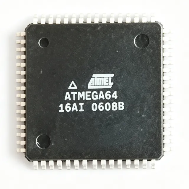
ATMEGA16-16AI - 8-bit AVR MCU 16KB Flash 16MHz TQFP-44 | Microchip
Référence : ATMEGA16-16AI ✓ Actif| Qté | Prix unitaire | Total |
|---|---|---|
| 1 | $5.86 | $5,86 |
| 10 | $5.28 | $52,80 |
| 100 | $4.62 | $462,00 |
| 500 | $4.18 | $2 090,00 |
| 1 000 | $3.82 | $3 820,00 |
ATMEGA16-16AI Présentation
An 8-bit AVR microcontroller is a single-chip computer that integrates a processor core, program memory, data memory, and peripherals such as timers, UART, SPI, and ADC on one die. Within the semiconductor hierarchy it sits under microcontrollers -> embedded processors -> integrated circuits, and the AVR family is the direct ancestor of the ATmega line used across the embedded industry.
Key features of the ATMEGA16-16AI include the AVR enhanced RISC architecture executing 131 powerful instructions, most in a single clock cycle, with 32 general-purpose working registers. The self-programming Flash supports in-system programming via SPI, while the on-chip JTAG interface enables boundary-scan debugging and programming. The 8-channel 10-bit ADC with internal reference supports direct analog sensor interfacing, and four PWM channels serve motor and LED control.
Technically, the single-cycle execution model delivers approximately 1 MIPS per MHz, allowing designers to trade clock speed against power consumption. The 16 suffix denotes a maximum 16 MHz clock; the A suffix denotes the industrial temperature grade; the I suffix combined with the AU lead-free package code marks RoHS-relevant package variants of the ATmega16 core family.
Typical applications include industrial control panels, motor control and power inverter user interfaces, sensor nodes with analog inputs, and legacy embedded systems where the ATmega16 architecture, code base, and toolchain (AVR Studio, avr-gcc) are already qualified.
Design consideration: the ATMEGA16-16AI is a 5V device - level shifting is required to interface with 3.3V peripherals, and VCC/AVCC decoupling plus a clean AREF path are essential for ADC accuracy.
This page synthesizes verified distributor pricing, drop-in alternatives within the same TQFP-44 footprint, and practical design guidance not consolidated in the manufacturer datasheet.
Alternatives de remplacement direct pour ATMEGA16-16AI — même boîtier, compatible broche à broche. Les références à boîtier différent nécessitant une retouche du PCB sont exclues.
Variantes de cette série
Modèles de la même série directement compatibles avec ATMEGA16-16AI (même facteur de forme et même empreinte) — différant par Maximum Clock Frequency, Operating Temperature, Mounting Type, Package, Core Architecture.
Outil de comparaison rapide — sélectionnez des références alternatives pour une comparaison côte à côte :
ATMEGA16-16AU
✓ En stock
$4.41 / unité
Voir la fiche technique →ATMEGA16A-AU
✓ En stock
$2.05 / unité
Voir la fiche technique →ATMEGA16U2-AU
✓ En stock
$1.86 / unité
Voir la fiche technique →ATMEGA32-16AI
📋 Alternative de référence (hors catalogue)
ATMEGA16L-8AC
📋 Alternative de référence (hors catalogue)
ATMEGA16-16AI Valeurs maximales et caractéristiques électriques
| Core Architecture | 8-bit AVR RISC |
| Flash Program Memory | 16 KB (8K x 16) In-System Programmable |
| SRAM | 1 KB |
| EEPROM | 512 B |
| Fréquence d'horloge maximale | 16 MHz |
| Throughput | Up to 16 MIPS at 16 MHz |
| Instruction Set | 131 instructions, most single-cycle |
| ADC | 8-channel, 10-bit |
| Debug Interface | JTAG (on-chip debug and boundary scan) |
| Tension d'alimentation | 5 V (VCC) |
| Température de fonctionnement | -40C to +85C (industrial, I grade) |
| Boîtier | 44-TQFP (10 x 10 mm) |
| Type de montage | Surface Mount (SMD/SMT) |
| Timers | Two 8-bit + one 16-bit |
| Communication Interfaces | USART, SPI, TWI (I2C-compatible) |
| In-System Programming | Yes, via SPI |
Guide de configuration des broches du ATMEGA16-16AI 44-tqfp (10 x 10 mm)
Configuration des broches du ATMEGA16-16AI (boîtier 44-tqfp (10 x 10 mm)). Ce circuit intégré numérique comprend des GPIO, des interfaces de communication (UART, SPI, I2C) et des broches d'alimentation. Consultez la fiche technique du fabricant pour les fonctions alternatives des broches et les options de configuration. Indispensable pour la conception de systèmes embarqués et la conception de circuits imprimés.

Aucune donnée de brochage détaillée disponible pour ATMEGA16-16AI.
Consultez la fiche technique pour la configuration complète des broches.
Applications typiques
ATMEGA16-16AI convient pour 6 applications: Industrial Control Panels, Analog Sensor Nodes, DC Motor and PWM Control, Legacy Embedded System Maintenance, Power Inverter User Interfaces, Education and Hobby Embedded Platforms.
Industrial Control Panels
The ATMEGA16-16AI fits industrial panel controllers because its 5V supply, -40C to +85C industrial temperature grade, and 44-TQFP footprint with 32 GPIO lines cover relay sequencing, button debouncing, and indicator driving in a single chip. The 16 MIPS throughput at 16 MHz is ample for scan-cycle state machines, while the 512 B EEPROM stores setpoints and counters that survive power loss. JTAG on-chip debugging shortens commissioning of panel logic, and in-system SPI programming allows firmware updates without desoldering. Use opto-isolated inputs on the ADC and keep VCC decoupled with 100 nF per supply pin for noise immunity in electrically harsh cabinets.
Recommandé
Analog Sensor Nodes
The integrated 8-channel 10-bit ADC makes the ATMEGA16-16AI a strong fit for multi-sensor acquisition nodes: temperature, pressure, and potentiometer inputs can be sampled directly without an external converter. AVCC must be kept clean (separate LC filter from VCC) and AREF decoupled to preserve effective ADC accuracy; with a stable reference the converter supports 10-bit resolution adequate for condition-monitoring thresholds. USART and TWI interfaces forward readings to gateways, and the 16 KB Flash retains calibration routines. Sleep modes reduce average current in battery-buffered installations, trading sample rate against power at roughly 1 MIPS per MHz efficiency.
Recommandé
DC Motor and PWM Control
With four PWM channels generated by two 8-bit timers and one 16-bit timer, the ATMEGA16-16AI drives DC motor speed control and simple multi-phase sequencing. The 16-bit timer's input capture measures tacho pulses for closed-loop speed regulation, while the 10-bit ADC reads current shunts for overload protection - all without external peripherals. Pairing the MCU with an IR2110-class gate driver bridges low-side/high-side MOSFET stages in half-bridge drives. Designers should set PWM frequency above the audible band where possible, ensure dead-time in software for H-bridge operation, and verify that 16 MIPS loop rate meets the control bandwidth target.
Recommandé
Legacy Embedded System Maintenance
A primary ongoing role of the ATMEGA16-16AI is sustaining fielded AVR-based equipment. Its exact instruction-set and peripheral compatibility with the original ATmega16 die means existing binaries and avr-gcc/AVR Studio projects port without requalification when sourced as replacement stock; the ATMEGA16A-AU refresh in the same TQFP-44 footprint is the strategic second source. JTAG boundary scan supports fixture-based production test of repaired boards, and the 16 MHz/5V rating matches the original power budget exactly. Procurement teams should buy buffer stock for end-of-service equipment because distributor stock of this legacy part is intermittent, as DigiKey's 0-unit listing shows.
Recommandé
Power Inverter User Interfaces
Power inverter and UPS front panels benefit from the ATMEGA16-16AI combination of TWI (I2C) for reading power-monitoring ICs, ADC channels for potentiometer-set points, and 16-bit timer PWM for buzzer and backlight control. The 5V logic directly drives 5V optocouplers that isolate the user interface from the high-voltage stage, a common architecture in 24V/48V industrial inverters. Industrial temperature rating keeps the interface alive in hot enclosures, and 1 KB SRAM accommodates menu structures and event logs in EEPROM. Keep the MCU ground on the isolated low-voltage side and route ADC traces away from switching nodes to protect measurement fidelity.
Recommandé
Education and Hobby Embedded Platforms
The ATmega16 family remains a staple in university embedded-systems laboratories and maker projects because JTAG debugging, in-system SPI programming, and free gcc toolchains make every peripheral (timers, UART, ADC, TWI, SPI) observable at register level. The 44-TQFP student-friendly footprint is hand-solderable with modest skill, and abundant textbook material targets the ATmega16 specifically. Note for newcomers: this part lacks seamless Arduino ecosystem support - community cores such as MightyCore fill the gap but require manual configuration, so plain AVR C toolchains are the smoother learning path. Its 5V operation also simplifies breadboard interfacing with classic 5V peripherals and displays.
Recommandé
Récapitulatif des produits recommandés
Données de référence d'ingénierie pour ATMEGA16-16AI — comparaison, recommandations de conception et informations de conformité.
Guide de sélection
Comparaison avec les alternatives
| Paramètre | Ce produit | ATMEGA16-16AU | ATMEGA16A-AU | ATMEGA32-16AI | ATMEGA16L-8AC |
|---|---|---|---|---|---|
| Package | 44-TQFP (10x10 mm) | 44-TQFP (10x10 mm) - same | 44-TQFP (10x10 mm) - same | 44-TQFP (10x10 mm) - same | 44-TQFP (10x10 mm) - same |
| Brand | Microchip Technology (Atmel) | Microchip Technology (Atmel) | Microchip Technology (Atmel) | Microchip Technology (Atmel) | Microchip Technology (Atmel) |
| Flash Memory | 16 KB | 16 KB | 16 KB | 32 KB | 16 KB |
| SRAM | 1 KB | 1 KB | 1 KB | 2 KB | 1 KB |
| Max Clock Frequency | 16 MHz | 16 MHz | 16 MHz | 16 MHz | 8 MHz |
| ADC | 8-channel 10-bit | 8-channel 10-bit | 8-channel 10-bit | 8-channel 10-bit | 8-channel 10-bit |
| Operating Temperature | -40C to +85C (industrial) | -40C to +85C (industrial) | -40C to +85C (industrial) | -40C to +85C (industrial) | Commercial grade |
Principaux différenciateurs
- Full 16 MHz speed grade at 5V (vs ATMEGA16L-8AC)
- Integrated 8-channel 10-bit ADC (vs ATMEGA16U2-AU)
- Cost-efficient entry point in the mega family (vs ATMEGA32-16AI)
Notes de conception
The ATMEGA16-16AI is a 5V-only device at the 16 MHz speed grade. Place 100 nF ceramic decoupling capacitors directly at VCC and AVCC pins, plus a 10 uF bulk capacitor near the regulator output. AVCC must stay within +/-0.3V of VCC per the Atmel datasheet; if VCC is noisy, feed AVCC through an LC filter (ferrite bead plus 100 nF/10 uF) to protect ADC accuracy. For 3.3V systems, add bidirectional level shifters rather than derating VCC, which would violate the 16 MHz operating point.
Route the JTAG header (TCK, TMS, TDI, TDO on PC2-PC5) to a standard 2x5 header on production boards even if debugging is finished - it enables boundary-scan production test. Keep the AREF pin with its own dedicated 100 nF capacitor to ground; never connect AREF to VCC directly when using the internal reference. Crystals for XTAL1/XTAL2 should sit within 10 mm of the pins with appropriate load capacitors, and keep fast PD/PB signal traces away from the crystal net to avoid start-up jitter.
Three frequent mistakes with ATmega16 designs: (1) forgetting that JTAG is fuse-enabled by default, blocking PC2-PC7 general-purpose use - clear the JTAGEN fuse in final firmware if those I/O are needed; (2) assuming Arduino ecosystem compatibility - this part requires community cores (e.g., MightyCore) or plain avr-gcc, unlike ATmega328P; (3) ignoring supply-chain risk - DigiKey showed 0 stock for the AU variant as of 2026-09-16, so qualify ATMEGA16A-AU and hold safety stock for production programs.
Informations de conformité
Compliance status not stated in retrieved web data; confirm RoHS/REACH status on the Microchip product page or certificate of conformance before specifying. One comparison source listed RoHS 'N' for a related variant - verify per exact ordering code.
