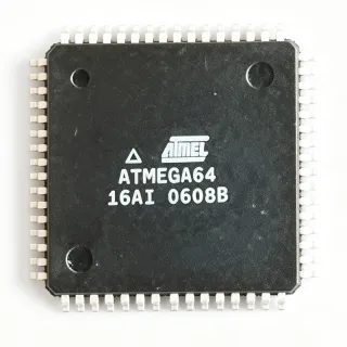
ATMEGA162V-8AJ - AVR 8-bit MCU 16KB 8MHz TQFP-44 | Microchip
Référence : ATMEGA162V-8AJ ✓ Actif| Qté | Prix unitaire | Total |
|---|---|---|
| 1 | $4.42 | $4,42 |
| 10 | $3.95 | $39,50 |
| 100 | $3.42 | $342,00 |
| 500 | $3.08 | $1 540,00 |
| 1 000 | $2.74 | $2 740,00 |
ATMEGA162V-8AJ Présentation
An 8-bit AVR microcontroller is a Harvard-architecture processor that executes most instructions in a single clock cycle, achieving throughput close to 1 MIPS per MHz. Within the power-management hierarchy, it integrates the CPU core, program memory, SRAM, EEPROM, timers, serial peripherals, and general-purpose I/O on a single die, replacing multi-chip solutions in embedded control systems.
Key features include 16KB (8K x 16) self-programmable Flash with 512B EEPROM and 1KB internal SRAM, 35 programmable I/O lines, and five sleep modes (Idle, Power-save, Power-down, Standby, and Extended Standby) for aggressive power optimization. The peripheral set is unusually rich for its class: dual USARTs for two independent serial channels, an SPI interface for high-speed peripheral expansion, JTAG for on-chip debugging and boundary scan, and two 8-bit plus one 16-bit timer/counters with PWM capability.
The AVR core combines a RISC instruction set executed mostly in one cycle with a two-stage pipeline, allowing the designer to trade clock speed directly against power consumption. The V speed grade runs reliably from 1.8V, enabling battery-powered designs that cannot tolerate the 2.7V minimum of the ATmega162L or the 4.5V minimum of the standard ATmega162.
Typical applications include industrial control panels, dual-channel serial communication nodes, keypad-and-display user interfaces, and battery-operated instrumentation where wide supply tolerance matters.
Design consideration: the V grade caps the clock at 8MHz, so verify that your firmware's timing budget fits within 8 MIPS; if not, the 16MHz ATMEGA162-16AU is the same-footprint upgrade.
This page adds distributor availability data, drop-in alternatives, and engineering design notes not found in the manufacturer datasheet.
Alternatives de remplacement direct pour ATMEGA162V-8AJ — même boîtier, compatible broche à broche. Les références à boîtier différent nécessitant une retouche du PCB sont exclues.
Variantes de cette série
Modèles de la même série directement compatibles avec ATMEGA162V-8AJ (même facteur de forme et même empreinte) — différant par Package, Operating Temperature, Mounting Type, Core Architecture, RoHS Status.
Outil de comparaison rapide — sélectionnez des références alternatives pour une comparaison côte à côte :
ATMEGA162V-8AU
✅ Remplacement direct✓ En stock
$4.38 / unité
Voir la fiche technique →ATMEGA162V-1AC
✅ Remplacement direct ⚠️ Spécifications non vérifiées✓ En stock
$3.35 / unité
Voir la fiche technique →ATMEGA162L-8AU
✅ Remplacement direct ⚠️ Spécifications non vérifiées📋 Alternative de référence (hors catalogue)
ATMEGA162-16AU
✅ Remplacement direct ⚠️ Spécifications non vérifiées✓ En stock
$2.45 / unité
Voir la fiche technique →ATMEGA161L-4AI
✅ Remplacement direct ⚠️ Spécifications non vérifiées✓ En stock
$5.95 / unité
Voir la fiche technique →ATMEGA162V-8AJ Valeurs maximales et caractéristiques électriques
| Core | AVR 8-bit RISC |
| Flash Memory | 16 KB (8K x 16) |
| SRAM | 1 KB |
| EEPROM | 512 B |
| Fréquence d'horloge maximale | 8 MHz |
| Operating Voltage Range | 1.8 V to 5.5 V |
| Programmable I/O Lines | 35 |
| USART Channels | 2 |
| Timers | Two 8-bit, one 16-bit |
| SPI Interface | Yes |
| JTAG Interface | Yes (debug and boundary scan) |
| Sleep Modes | Idle, Power-save, Power-down, Standby, Extended Standby |
| Boîtier | 44-TQFP (10 x 10 mm) |
| Type de montage | Surface Mount |
| Statut RoHS | Compliant |
| ADC | None (no on-chip ADC) |
Guide de configuration des broches du ATMEGA162V-8AJ 44-tqfp (10 x 10 mm)
Configuration des broches du ATMEGA162V-8AJ (boîtier 44-tqfp (10 x 10 mm)). Ce circuit intégré numérique comprend des GPIO, des interfaces de communication (UART, SPI, I2C) et des broches d'alimentation. Consultez la fiche technique du fabricant pour les fonctions alternatives des broches et les options de configuration. Indispensable pour la conception de systèmes embarqués et la conception de circuits imprimés.

Aucune donnée de brochage détaillée disponible pour ATMEGA162V-8AJ.
Consultez la fiche technique pour la configuration complète des broches.
Applications typiques
ATMEGA162V-8AJ convient pour 6 applications: Industrial Control Panels, Dual-Channel Serial Communication Nodes, Battery-Powered Instrumentation, Keypad and Display User Interfaces, Legacy ATmega161 Board Migration, Embedded Training and Prototyping.
Industrial Control Panels
The ATMEGA162V-8AJ fits industrial control panels where multiple serial devices must coexist: its two independent USARTs can service an RS-485 fieldbus on one channel and an HMI or configuration terminal on the other at the same time. The 1.8V to 5.5V supply window tolerates brownout conditions typical of factory floors, and five sleep modes cut standby draw between duty cycles. With 35 I/O lines, relays, indicator lamps, and keypads can be driven directly, while the 16KB Flash with self-programming supports field firmware updates through a bootloader. Surface-mount 44-TQFP construction withstands vibration better than through-hole alternatives.
Recommandé
Dual-Channel Serial Communication Nodes
For gateways and protocol converters, the defining feature of the ATMEGA162V-8AJ is its dual USART architecture, rare in 16KB-class 8-bit MCUs. One UART can run Modbus RTU while the second services a debug or telemetry link, eliminating an external UART expander IC, its board area, and its failure points. The SPI port adds high-speed peripheral expansion for SD-card logging or Ethernet MACs, and JTAG enables on-chip debugging of interrupt-driven serial firmware. At 8MHz the AVR core yields roughly 8 MIPS, sufficient for buffering both serial streams with the 1KB SRAM acting as a small FIFO.
Recommandé
Battery-Powered Instrumentation
The V speed grade is what makes ATMEGA162V-8AJ attractive for battery products: guaranteed operation from 1.8V means the MCU keeps running across the full discharge curve of two alkaline cells, and the 512B EEPROM stores calibration constants without external NVRAM. The datasheet's five sleep modes, particularly Power-down and Extended Standby, allow duty-cycled designs that wake on external interrupt or timer, sample, transmit over USART, and return to sleep, dramatically extending battery life versus always-on operation at 8MHz.
Recommandé
Keypad and Display User Interfaces
Human-machine interface boards benefit from the ATMEGA162V-8AJ's generous I/O count: 35 programmable lines drive a 4x4 matrix keypad plus a character LCD in 4-bit mode directly, with port PC often allocated to the display bus and port PA to scanning and backlight control. Timer PWM channels provide LCD backlight dimming and buzzer tones without extra components. The dual USART lets the HMI forward commands to a main controller while debugging on the second port, and JTAG shortens firmware iteration during UI development with breakpoints and single stepping.
Recommandé
Legacy ATmega161 Board Migration
The ATmega162 datasheet states that the device is 100% pin compatible with ATmega161 and can replace it on existing printed circuit boards, making ATMEGA162V-8AJ the standard continuation path for aging ATmega161 designs that face end-of-life supply risk. Migration requires only firmware review: fuse-bit locations and some electrical characteristics differ between the generations, so production programming scripts and any code reading fuse bytes must be updated. Once verified, the migration adds the second USART, more SRAM, and JTAG debugging to an unchanged PCB layout.
Recommandé
Embedded Training and Prototyping
Universities and prototyping labs choose the ATMEGA162V-8AJ because the 44-TQFP, hand-solderable 0.8mm-pitch package combines with Atmel's mature toolchain: JTAG debugging, ISP programming through SPI, and the free AVR GCC toolchain cover the full learning loop. The two USARTs let students study interrupt-driven duplex serial communication in one lab exercise, and the 1.8V to 5.5V range means one board revision runs from bench supplies or batteries alike. Because the family spans 1MHz to 16MHz grades in one footprint, coursework scales with a single PCB design.
Recommandé
Récapitulatif des produits recommandés
Données de référence d'ingénierie pour ATMEGA162V-8AJ — comparaison, recommandations de conception et informations de conformité.
Guide de sélection
Comparaison avec les alternatives
| Paramètre | Ce produit | ATMEGA162V-8AU | ATMEGA162V-1AC | ATMEGA162L-8AU | ATMEGA162-16AU | ATMEGA161L-4AI |
|---|---|---|---|---|---|---|
| Package | 44-TQFP (10x10) | 44-TQFP (10x10) - same | 44-TQFP (10x10) - same | 44-TQFP (10x10) - same | 44-TQFP (10x10) - same | 44-TQFP (10x10) - same |
| Brand | Microchip Technology | Microchip Technology | Microchip Technology | Microchip Technology | Microchip Technology | Microchip Technology |
| Operating Voltage | 1.8 V to 5.5 V | 1.8 V to 5.5 V | 1.8 V to 5.5 V | 2.7 V to 5.5 V | 4.5 V to 5.5 V | 2.7 V to 5.5 V |
| Max Clock Frequency | 8 MHz | 8 MHz | 1 MHz | 8 MHz | 16 MHz | 4 MHz |
| Flash | 16 KB | 16 KB | 16 KB | 16 KB | 16 KB | 16 KB |
| SRAM | 1 KB | 1 KB | 1 KB | 1 KB | 1 KB | 512 B |
| USART Count | 2 | 2 | 2 | 2 | 2 | 1 |
| JTAG Debug | Yes | Yes | Yes | Yes | Yes | No |
| On-chip ADC | No | No | No | No | No | No |
Principaux différenciateurs
- Dual USART in 16KB class (vs ATMEGA16-16AJ)
- Widest supply range in the ATmega162 family (vs ATMEGA162L-8AU)
- JTAG on-chip debugging (vs ATMEGA161L-4AI)
Notes de conception
The V speed grade is voltage-derated: guaranteed operation is 1.8V to 5.5V at 0 to 8MHz, but do not raise the clock above 8MHz even at 5V, since the V grade is not characterized for it. For designs between 2.7V and 5.5V needing margin against supply droop, the L variant adds headroom documentation. Add 100nF ceramic decoupling on VCC pins plus 10uF bulk, and use the internal brown-out detector fuse so SRAM contents stay valid during slow supply decay in battery systems.
Migrating from ATmega161 is electrically plug-in but not firmware-transparent: the datasheet explicitly warns that fuse-bit locations and some electrical characteristics differ between ATmega161 and ATmega162. Production programmers and any code that reads lock/fuse bytes must be updated. Also note there is no on-chip ADC; designs ported from ATmega16 assume analog inputs that this device cannot measure. Finally, JTAG pins default to JTAG function at reset - disable the JTAGEN fuse if you need PC port pins back.
The 44-TQFP 0.8mm pitch is hand-solderable, but thermal relief matters little since dissipation is under 100mW in most clock configurations - no thermal pad is required. Route the two USART pairs away from the 16MHz-range SPI lines to limit crosstalk into UART sampling windows; at 8MHz system clock, keep UART lines under 15cm when possible. Provide an ISP header on PB5-PB7 (MOSI/MISO/SCK) plus reset for in-system programming, or use JTAG via PE port for full debug.
Informations de conformité
RoHS compliance indicated by DigiKey listing for the ATMEGA162V-8AJ; other compliance attributes should be confirmed via Microchip's product page.