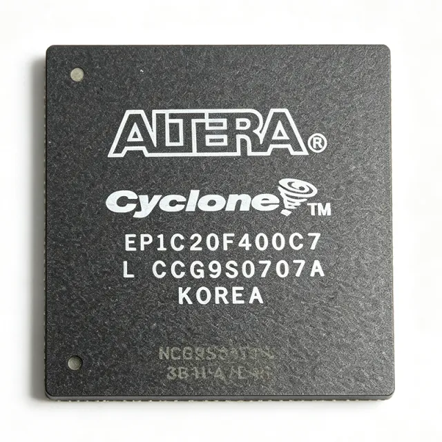
EP1C20F400C7 - Cyclone FPGA 20,060 LE 301 I/O 400-BGA | Intel
Référence : EP1C20F400C7 ✓ Actif| Qté | Prix unitaire | Total |
|---|---|---|
| 1 | $78.5 | $78,50 |
| 10 | $70.2 | $702,00 |
| 100 | $62.8 | $6 280,00 |
| 500 | $55.4 | $27 700,00 |
| 1 000 | $48.9 | $48 900,00 |
EP1C20F400C7 Présentation
An FPGA (Field Programmable Gate Array) is a reprogrammable logic device whose internal architecture consists of configurable logic blocks (CLBs), programmable interconnects, embedded memory blocks, and a perimeter of user I/O cells. In the taxonomy of digital semiconductors, FPGAs sit between ASICs (highest NRE, lowest unit cost at volume) and microcontrollers (fixed hardware, lowest flexibility), making them ideal for glue logic, custom datapaths, and hardware-accelerated DSP. The Cyclone family was Altera's first process-node family explicitly optimized for low power and low unit cost.
Key features of the EP1C20F400C7 include 20,060 logic elements arranged in 2,006 logic array blocks (LABs), 288 kbits of embedded SRAM distributed across M4K memory blocks, 301 single-ended I/O (or differential pairs) supporting LVDS, LVTTL, LVCMOS, SSTL, and PCI standards, one PLL per device for clock conditioning, and 20 global clock networks. The 400-ball FineLine BGA package measures 21 mm × 21 mm with a 1.00 mm ball pitch, allowing mid-density PCB designs without via-in-pad or HDI stackups.
Technically, the device uses a 4-input look-up table (LUT) as its basic logic element, supports true dual-port and single-port RAM, and provides dedicated multiplier blocks (3 × 3 multipliers) for DSP applications. Configuration is loaded via an industry-standard passive serial (PS), passive parallel synchronous (PPS), passive parallel asynchronous (PPA), or JTAG interface. The Quartus II design software (legacy: 6.0 through 13.1) supports the full design flow from synthesis to programming file generation.
Typical applications include industrial control and factory automation, automotive infotainment and driver-assistance subsystems, consumer video processing, communications line cards, and prototyping platforms for ASIC emulation. The combination of high logic density, modest power envelope, and a JTAG-based debug interface also makes the EP1C20F400C7 a popular choice in university curricula for teaching digital design with a real silicon target.
When designing with this part, engineers should plan for 1.5 V core decoupling with multiple 0.1 µF + bulk capacitors, observe the LVDS I/O banking rules (each bank has a VCCIO reference), and use the Altera ByteBlaster II or USB-Blaster cable for in-system programming. The 400-BGA package requires careful PCB layout: matched-length traces for clock pairs, and a thermal copper pour under the package to spread the moderate (~1.5 W typical) dissipation.
This page synthesizes distributor pricing, drop-in same-density alternatives, and practical design notes not found in the legacy Cyclone datasheet alone.
Alternatives de remplacement direct pour EP1C20F400C7 — même boîtier, compatible broche à broche. Les références à boîtier différent nécessitant une retouche du PCB sont exclues.
Variantes de cette série
Modèles de la même série directement compatibles avec EP1C20F400C7 (même facteur de forme et même empreinte) — différant par Package, Process Technology, Speed Grade, PLLs, RoHS Status.
Outil de comparaison rapide — sélectionnez des références alternatives pour une comparaison côte à côte :
EP1C20F400C6N
✓ En stock
$53.1 / unité
Voir la fiche technique →EP1C20F400C6AC
✓ En stock
$52 / unité
Voir la fiche technique →EP1C20F400C6AB
✓ En stock
$65.8 / unité
Voir la fiche technique →EP1C20F400C6
✓ En stock
$18.95 / unité
Voir la fiche technique →EP1C20F40017
✓ En stock
$24.8 / unité
Voir la fiche technique →EP1C20F400
✓ En stock
$58.9 / unité
Voir la fiche technique →EP1C20F400C7 Valeurs maximales et caractéristiques électriques
| Family | Cyclone |
| Process Technology | 0.13 µm SRAM |
| Logic Elements | 20,060 LE |
| Logic Array Blocks (LABs) | 2,006 |
| Embedded Memory | 294,912 bits (288 kbit) |
| M4K Memory Blocks | 64 |
| Maximum User I/O | 301 |
| PLLs | 2 |
| Global Clock Networks | 20 |
| Core Voltage | 1.5 V |
| Boîtier | 400-ball FineLine BGA (FBGA-400) |
| Package Dimensions | 21 mm × 21 mm |
| Ball Pitch | 1.00 mm |
| Température de fonctionnement | 0°C to +85°C (commercial) |
| Type de montage | Surface Mount |
| Configuration Interface | JTAG / Passive Serial / Passive Parallel |
Configuration des broches de EP1C20F400C7
| Broche A1 | I/O — General-purpose user I/O, bank 1 |
| Broche A2 | I/O — General-purpose user I/O, bank 1 |
| Broche B1 | VCCINT — 1.5 V core supply |
| Broche B2 | GND — Ground |
| Broche C3 | I/O — General-purpose user I/O, bank 2 |
| Broche C4 | I/O — General-purpose user I/O, bank 2 |
| Broche D5 | VCCIO1 — I/O bank 1 reference voltage |
| Broche D6 | I/O — General-purpose user I/O, bank 1 |
| Broche E7 | I/O — General-purpose user I/O, bank 3 |
| Broche E8 | VCCIO2 — I/O bank 2 reference voltage |
| Broche F9 | I/O — General-purpose user I/O, bank 4 |
| Broche F10 | GND — Ground |
| Broche G11 | I/O — General-purpose user I/O, bank 5 |
| Broche G12 | VCCIO3 — I/O bank 3 reference voltage |
| Broche H13 | I/O — General-purpose user I/O, bank 6 |
| Broche H14 | I/O — General-purpose user I/O, bank 6 |
| Broche J15 | VCCIO4 — I/O bank 4 reference voltage |
| Broche J16 | I/O — General-purpose user I/O, bank 7 |
| Broche K17 | TCK — JTAG test clock |
| Broche K18 | TMS — JTAG test mode select |
| Broche L19 | TDI — JTAG test data in |
| Broche L20 | TDO — JTAG test data out |
| Broche M18 | nSTATUS — Configuration status |
| Broche M19 | nCONFIG — Configuration control |
| Broche N17 | DCLK — Configuration clock |
| Broche N18 | DATA0 — Configuration data input |
| Broche P15 | PLL1_OUT — PLL 1 output |
| Broche P16 | PLL2_OUT — PLL 2 output |
| Broche R13 | I/O — General-purpose user I/O, bank 8 |
| Broche R14 | GND — Ground |
Applications typiques
EP1C20F400C7 convient pour 6 applications: Industrial Control and Factory Automation, Automotive Infotainment and Driver Assistance, Consumer Video Processing Devices, Communications Line Cards and Network Edge, ASIC Prototyping and Emulation Platforms, University Digital Design Education.
Industrial Control and Factory Automation
The EP1C20F400C7 fits factory automation with 20,060 logic elements that absorb multi-axis motion-control state machines, PID loops, and EtherCAT/IP protocol handlers in a single chip. The 301 user I/O pins accommodate dozens of 24 V opto-isolated inputs, encoder channels, and PWM outputs to motor drivers without external mux logic. Its 1.5 V core and 0.13 µm process keep typical dissipation near 1.5 W, allowing sealed IP67 enclosures without active cooling. Commercial 0°C to +85°C operation is adequate for indoor control cabinets; for harsh environments the EP1C20F400I7 industrial-temperature variant is the preferred drop-in.
Recommandé
Automotive Infotainment and Driver Assistance
The 20,060 logic elements and 288 kbit embedded RAM of the EP1C20F400C7 are well-suited to early-generation automotive infotainment head units, rear-seat entertainment, and surround-view camera fusion, where multiple video streams must be merged with overlays and compression in real time. The dedicated 3 × 3 multipliers accelerate H.264/MJPEG decode at SD resolutions, while the LVDS-capable I/O simplify connection to automotive flat-panel displays. Designers must select the -I7 industrial variant (-40°C to +100°C) for under-hood and dashboard use; the EP1C20F400C7 standard commercial grade is only suitable for cabin-mounted units. The FBGA-400 footprint also enables multi-PCB stacking inside tight dashboard enclosures.
Recommandé
Consumer Video Processing Devices
The EP1C20F400C7's 20,060 logic elements handle HD video scaling, de-interlacing, and color-space conversion in set-top boxes, video capture cards, and digital media adapters. The two on-chip PLLs derive multiple pixel-clock domains from a single 27 MHz crystal, while 288 kbit of embedded RAM serves as line buffers without external SDRAM for 720p pipelines. The 301 user I/O pins allow direct connection to HDMI receivers, video DACs, and SD card interfaces in parallel. Cost-sensitive consumer designs typically target the EP1C20F400C6 speed grade to reduce unit cost by approximately 8-12% versus the -7 grade without sacrificing video throughput at standard frame rates.
Recommandé
Communications Line Cards and Network Edge
Telecommunications line cards that terminate T1/E1, ISDN PRI, or low-density Ethernet traffic benefit from the EP1C20F400C7's 301 I/O for per-channel framer logic, while the 288 kbit embedded RAM buffers packet payloads at wire speed. The two PLLs generate independent clocks for upstream and downstream directions, and the 20 global clock networks feed multiple PHY interfaces without external clock-tree ICs. The FBGA-400 footprint on 1.0 mm pitch allows 8-layer PCB backplanes without HDI stackups, and the 1.5 V core keeps the per-port power budget within the 5 W typical slot envelope. The EP1C20F400I7 variant extends operation to outdoor -40°C cabinets.
Recommandé
ASIC Prototyping and Emulation Platforms
Engineering teams use the EP1C20F400C7 as a building block for ASIC and SoC prototyping, mapping RTL partitions into 20,060 logic elements per device and chaining multiple FPGAs over LVDS for high-fanout signal emulation. The 301 I/O pins double as virtual chip pads, allowing thousands of inter-FPGA connections on a single backplane. The 288 kbit embedded RAM emulates small register files and FIFOs without external memory, and the JTAG configuration chain simplifies per-device programming in multi-FPGA arrays. Quartus II 13.1 (the last release supporting Cyclone I) provides the synthesis and place-and-route flow; for new emulation projects, Cyclone IV GX or Cyclone 10 LP devices are recommended successors.
Recommandé
University Digital Design Education
The EP1C20F400C7 appears in legacy Altera/Intel DE2 development boards and remains widely available for university digital logic courses. Students design state machines, ALU datapaths, and simple processors using the 20,060 logic elements, with 301 I/O supporting switches, LEDs, seven-segment displays, and VGA connectors. The JTAG configuration interface and ByteBlaster II cable allow real-time in-system programming from Quartus II Web Edition (free), making it ideal for teaching hardware description languages (VHDL/Verilog) and synchronous design. The Cyclone I device family is mature enough that textbooks, lab manuals, and reference designs are abundant, which lowers the barrier to course adoption. Many institutions continue using Cyclone I boards while gradually migrating curricula to Cyclone IV E or Cyclone 10 LP platforms.
Recommandé
Récapitulatif des produits recommandés
Données de référence d'ingénierie pour EP1C20F400C7 — comparaison, recommandations de conception et informations de conformité.
Guide de sélection
Comparaison avec les alternatives
| Paramètre | Ce produit | EP1C20F400C6N | EP1C20F400C6AC | EP1C20F400C6AB | EP1C20F400C6 | EP1C20F40017 | EP1C20F400 |
|---|---|---|---|---|---|---|---|
| Brand | Intel | Intel | Intel | Intel | Intel | Intel | Intel |
| Package | FBGA-400 | FBGA-400 - same | FBGA-400 - same | FBGA-400 - same | FBGA-400 - same | FBGA-400 - same | FBGA-400 - same |
| Logic Elements | 20,060 LE | 20,060 LE | 20,060 LE | 20,060 LE | 20,060 LE | 20,060 LE | 20,060 LE |
| Embedded Memory | 288 kbit | 288 kbit | 288 kbit | 288 kbit | 288 kbit | 288 kbit | 288 kbit |
| User I/O Count | 301 | 301 | 301 | 301 | 301 | 301 | 301 |
| Speed Grade | -7 | -6 (slower) | -6 (slower) | -6 (slower) | -6 (slower) | -7 (equivalent) | Per suffix |
| Temperature Range | 0°C to +85°C (commercial) | 0°C to +85°C | 0°C to +85°C | 0°C to +85°C | 0°C to +85°C | Full commercial | Per suffix |
| Core Voltage | 1.5 V | 1.5 V | 1.5 V | 1.5 V | 1.5 V | 1.5 V | 1.5 V |
| Lifecycle Status | Obsolete | Obsolete | Obsolete | Obsolete | Obsolete | Obsolete | Per suffix |
Principaux différenciateurs
- Highest-density Cyclone I device in 400-ball BGA (vs EP1C12Q240C8N)
- Cyclone I family has identical toolchain support from Quartus II 6.0 through 13.1 (vs Cyclone IV E EP4CE22F17C8N)
- Speed grade -7 is the fastest Cyclone I option (vs EP1C20F400C6)
Notes de conception
Estimated: at typical utilization (60% LE, 50% memory, 100 MHz system clock) the EP1C20F400C7 dissipates approximately 1.5 W from the 1.5 V core supply. Provide at least three 0.1 µF X7R ceramic decoupling capacitors placed within 5 mm of the VCCINT pins, plus a single 47 µF X5R bulk capacitor near the package. Use a dedicated LDO regulator (e.g., TI TPS7A4701) rather than a switching converter when designing for noise-sensitive analog I/O, as VCCINT ripple below 30 mV is required for reliable PLL operation.
The 400-ball FineLine BGA has 1.00 mm pitch and can be routed on a standard 4-layer PCB with 0.2 mm via capture. Use 0.10 mm trace width with 0.10 mm spacing between balls, fan-out to 0.20 mm via pads, and route signals on the top layer. Place a continuous GND plane on layer 2 directly under the BGA, and a VCCINT power island on layer 3. Avoid routing signal traces under the package perimeter to minimize crosstalk to JTAG and clock pins.
Configuration mode is set by MSEL[2:0] pins; tying them incorrectly prevents the FPGA from entering user mode after power-up. Use 4.7 kΩ pull-up or pull-down resistors on MSEL per the Cyclone Device Family datasheet, never leave them floating. Also ensure nCONFIG is held low during VCCINT ramp-up, then released after VCCINT reaches 1.45 V to trigger a clean configuration sequence. Failure to sequence properly results in nSTATUS staying low and the device never entering user mode.
Informations de conformité
RoHS, REACH, lead-free, halogen-free, and conflict-minerals status are not explicitly stated in the Verified Web Data for EP1C20F400C7; the Cyclone family datasheet references both leaded and lead-free package options. For automotive applications, the -Q suffix or EP4CE22F17C8N (Cyclone IV E with AEC-Q100 support) is recommended. Industrial-temperature variant EP1C20F400I7 should be selected for -40°C to +100°C operation.
