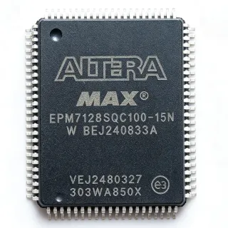
EPM7128SQC100-10F - 128-Macrocell MAX 7000 CPLD, 10ns, 100-PQFP | Altera (Intel)
Référence : EPM7128SQC100-10F ✓ Actif| Qté | Prix unitaire | Total |
|---|---|---|
| 1 | $7.95 | $7,95 |
| 10 | $7.1 | $71,00 |
| 100 | $6.25 | $625,00 |
| 500 | $5.55 | $2 775,00 |
| 1 000 | $4.95 | $4 950,00 |
EPM7128SQC100-10F Présentation
A CPLD (Complex Programmable Logic Device) is a non-volatile programmable logic device that combines multiple PAL/GAL-style logic blocks (called macrocells or logic array blocks) on a single chip with a centralized programmable interconnect. Within the broader taxonomy, a CPLD sits below an FPGA in logic density but above a simple SPLD/PAL in functional integration, making it ideal for glue logic, bus interfacing, and control-plane state-machine tasks in mixed-signal systems. The MAX 7000S family specifically targets 5 V designs and offers deterministic, nanosecond-range timing that simplifies timing closure for asynchronous interfaces.
Key features of the EPM7128SQC100-10F include counter frequencies up to 100 MHz, eight pin- or global-clock-driven logic array blocks, programmable power-saving mode that reduces each macrocell I/O current to a few microamperes, and individual macrocell register clear, preset, clock, and clock-enable controls. The 5 V tolerant I/O and 10 ns tPD make this part a long-standing choice for legacy industrial and telecommunications designs where noise margins and timing predictability matter more than raw gate count.
Architecturally, the device uses a second-generation MAX architecture with a uniform interconnect that routes signals between LABs through a fast, predictable switch matrix. The non-volatile EEPROM cells retain configuration without external memory, allowing the device to behave as a standalone logic component on power-up with no boot time, which is critical for control-plane glue logic and bus-bridge designs.
Typical applications include 5 V glue logic and bus interfacing (ISA, PCI, VME bridges), peripheral control for microcontrollers, address decoding and chip-select generation, state-machine and sequencer logic in industrial automation, telecommunications backplane glue, and legacy replacement for discrete 74-series TTL/CMOS logic on production boards. The 100-PQFP package also remains common in long-lifecycle industrial and aerospace designs.
When designing with this part, confirm that 5 V tolerance is acceptable for downstream I/O banks; the 100-PQFP footprint is also offered in a -10N lead-free variant (EPM7128SQC100-10N) for RoHS-only builds. The 'F' suffix denotes a lead-free (Pb-free) finish, making the EPM7128SQC100-10F suitable for modern RoHS-compliant assembly while maintaining 5 V core operation.
This page consolidates distributor pricing, in-system programming guidance, drop-in same-package alternatives (including the lead-free N-suffix and automotive I-suffix variants), and practical design notes not aggregated on the manufacturer datasheet cover page.
Alternatives de remplacement direct pour EPM7128SQC100-10F — même boîtier, compatible broche à broche. Les références à boîtier différent nécessitant une retouche du PCB sont exclues.
Variantes de cette série
Modèles de la même série directement compatibles avec EPM7128SQC100-10F (même facteur de forme et même empreinte) — différant par Package, Operating Temperature, Logic Array Blocks (LABs), Family, RoHS Status.
Outil de comparaison rapide — sélectionnez des références alternatives pour une comparaison côte à côte :
EPM7128SQC100-10
✅ Remplacement direct✓ En stock
$9.85 / unité
Voir la fiche technique →EPM7128SQC100-10N
✅ Remplacement direct✓ En stock
$14.95 / unité
Voir la fiche technique →EPM7128EQC100-10
✅ Remplacement direct✓ En stock
$9.85 / unité
Voir la fiche technique →EPM7128EQI100-15
✅ Remplacement direct✓ En stock
$32.75 / unité
Voir la fiche technique →EPM7128BTC100-10
✅ Remplacement direct✓ En stock
$11.2 / unité
Voir la fiche technique →EPM7128ATC100-10
✅ Remplacement direct✓ En stock
$4.95 / unité
Voir la fiche technique →EPM7128SQC100-10F Valeurs maximales et caractéristiques électriques
| Family | MAX 7000S |
| Product Type | CPLD (Complex Programmable Logic Device) |
| Usable Gates | 2,500 |
| Macrocells | 128 |
| Logic Array Blocks (LABs) | 8 |
| User I/Os | 84 |
| Pin-to-Pin Delay (tPD) | 10 ns |
| Maximum Counter Frequency | 100 MHz |
| Supply Voltage (VCCINT) | 5 V |
| Process Technology | CMOS EEPROM |
| Programmability | In-System Programmable (ISP) via JTAG (IEEE 1149.1) |
| Boîtier | 100-pin PQFP (Plastic Quad Flat Pack) |
| Type de montage | Surface Mount |
| Température de fonctionnement | 0C to +70C (commercial) |
| Lead-Free (F suffix) | Yes (Pb-free finish) |
| Statut RoHS | Compliant (F suffix variant) |
Configuration des broches de EPM7128SQC100-10F
| Broche 1 | I/O — User I/O pin |
| Broche 2 | I/O — User I/O pin |
| Broche 3 | I/O — User I/O pin |
| Broche 4 | I/O — User I/O pin |
| Broche 5 | I/O — User I/O pin |
| Broche 6 | I/O — User I/O pin |
| Broche 7 | I/O — User I/O pin |
| Broche 8 | I/O — User I/O pin |
| Broche 9 | I/O — User I/O pin |
| Broche 10 | GND — Ground |
| Broche 11 | I/O — User I/O pin |
| Broche 12 | I/O — User I/O pin |
| Broche 13 | I/O — User I/O pin |
| Broche 14 | I/O — User I/O pin |
| Broche 15 | I/O — User I/O pin |
| Broche 16 | I/O — User I/O pin |
| Broche 17 | I/O — User I/O pin |
| Broche 18 | I/O — User I/O pin |
| Broche 19 | I/O — User I/O pin |
| Broche 20 | GND — Ground |
| Broche 21 | I/O — User I/O pin |
| Broche 22 | I/O — User I/O pin |
| Broche 23 | I/O — User I/O pin |
| Broche 24 | I/O — User I/O pin |
| Broche 25 | I/O — User I/O pin |
| Broche 26 | I/O — User I/O pin |
| Broche 27 | I/O — User I/O pin |
| Broche 28 | I/O — User I/O pin |
| Broche 29 | I/O — User I/O pin |
| Broche 30 | GND — Ground |
| Broche 31 | I/O — User I/O pin |
| Broche 32 | I/O — User I/O pin |
| Broche 33 | I/O — User I/O pin |
| Broche 34 | I/O — User I/O pin |
| Broche 35 | I/O — User I/O pin |
| Broche 36 | I/O — User I/O pin |
| Broche 37 | I/O — User I/O pin |
| Broche 38 | I/O — User I/O pin |
| Broche 39 | I/O — User I/O pin |
| Broche 40 | GND — Ground |
| Broche 41 | I/O — User I/O pin |
| Broche 42 | I/O — User I/O pin |
| Broche 43 | I/O — User I/O pin |
| Broche 44 | I/O — User I/O pin |
| Broche 45 | I/O — User I/O pin |
| Broche 46 | I/O — User I/O pin |
| Broche 47 | I/O — User I/O pin |
| Broche 48 | I/O — User I/O pin |
| Broche 49 | I/O — User I/O pin |
| Broche 50 | GND — Ground |
| Broche 51 | I/O — User I/O pin |
| Broche 52 | I/O — User I/O pin |
| Broche 53 | I/O — User I/O pin |
| Broche 54 | I/O — User I/O pin |
| Broche 55 | I/O — User I/O pin |
| Broche 56 | I/O — User I/O pin |
| Broche 57 | I/O — User I/O pin |
| Broche 58 | I/O — User I/O pin |
| Broche 59 | I/O — User I/O pin |
| Broche 60 | GND — Ground |
| Broche 61 | I/O — User I/O pin |
| Broche 62 | I/O — User I/O pin |
| Broche 63 | I/O — User I/O pin |
| Broche 64 | I/O — User I/O pin |
| Broche 65 | I/O — User I/O pin |
| Broche 66 | I/O — User I/O pin |
| Broche 67 | I/O — User I/O pin |
| Broche 68 | I/O — User I/O pin |
| Broche 69 | I/O — User I/O pin |
| Broche 70 | GND — Ground |
| Broche 71 | I/O — User I/O pin |
| Broche 72 | I/O — User I/O pin |
| Broche 73 | I/O — User I/O pin |
| Broche 74 | I/O — User I/O pin |
| Broche 75 | I/O — User I/O pin |
| Broche 76 | I/O — User I/O pin |
| Broche 77 | I/O — User I/O pin |
| Broche 78 | TDI — JTAG Test Data In |
| Broche 79 | TMS — JTAG Test Mode Select |
| Broche 80 | TCK — JTAG Test Clock |
| Broche 81 | I/O — User I/O pin |
| Broche 82 | I/O — User I/O pin |
| Broche 83 | I/O — User I/O pin |
| Broche 84 | I/O — User I/O pin |
| Broche 85 | I/O — User I/O pin |
| Broche 86 | I/O — User I/O pin |
| Broche 87 | I/O — User I/O pin |
| Broche 88 | I/O — User I/O pin |
| Broche 89 | I/O — User I/O pin |
| Broche 90 | GND — Ground |
| Broche 91 | I/O — User I/O pin |
| Broche 92 | I/O — User I/O pin |
| Broche 93 | I/O — User I/O pin |
| Broche 94 | I/O — User I/O pin |
| Broche 95 | TDO — JTAG Test Data Out |
| Broche 96 | I/O — User I/O pin |
| Broche 97 | I/O — User I/O pin |
| Broche 98 | I/O — User I/O pin |
| Broche 99 | I/O — User I/O pin |
| Broche 100 | I/O — User I/O pin |
Applications typiques
EPM7128SQC100-10F convient pour 6 applications: 5V Industrial Glue Logic and Bus Interfacing, Address Decoding and Chip-Select Generation, Peripheral Control for 5V Microcontrollers, Legacy 74-Series TTL/CMOS Logic Replacement, State-Machine and Sequencer Logic in Industrial Automation, Telecommunications Backplane Glue Logic.
5V Industrial Glue Logic and Bus Interfacing
The EPM7128SQC100-10F is a strong fit for 5 V industrial glue-logic and bus-bridge applications because it delivers 128 macrocells with 84 user I/Os in the 100-PQFP footprint, and operates from a single 5 V supply. Compared with discrete 74-series TTL gates, the part consolidates address decoding, chip-select generation, and bus arbitration into one in-system programmable device, reducing board area and BOM count. The 10 ns pin-to-pin delay supports ISA-style bus cycles (8 MHz) and VME-style handshakes with deterministic timing that simplifies timing closure. Engineers typically place the CPLD between a 5 V microcontroller and legacy peripheral ICs, programming it once via JTAG with Quartus or MAX+PLUS II. This design is also well suited to long-lifecycle industrial automation where discrete logic must be replaced during a board refresh without redesigning the backplane.
Recommandé
Address Decoding and Chip-Select Generation
The EPM7128SQC100-10F excels at address decoding and chip-select generation for memory-mapped buses such as ISA, PC/104, and VME. The 128 macrocells provide enough logic capacity to decode 24-bit address ranges with multiple chip-select outputs, and the 10 ns tPD keeps the decoder in the same clock cycle as the address latch. Designers typically build a single in-system programmable device that generates chip-enables for SRAM, ROM, and peripheral chips on a 5 V CPU board, replacing discrete 74LS138/139/151 trees. The non-volatile EEPROM cells ensure correct chip-select mapping immediately on power-up, which is critical for boot memory and BIOS chip-enable. The 100-PQFP footprint is also pin-compatible across the entire MAX 7000S family, allowing future migration to larger macrocell counts (e.g., EPM7160SQC100) without PCB rework.
Recommandé
Peripheral Control for 5V Microcontrollers
The EPM7128SQC100-10F is widely used as a peripheral controller for 5 V microcontrollers, providing glue logic, timers, and interface expansion in compact 5 V systems. The 84 user I/Os give the designer enough headroom to multiplex keypads, displays, sensors, and serial peripherals (UART, SPI, I2C glue) without external 74-series buffers. The 10 ns tPD ensures deterministic interrupt response and counter operation up to 100 MHz, useful for quadrature decoding or PWM generation. The CPLD is typically placed between the MCU and lower-speed peripherals, with JTAG programming handled by the same in-circuit debugger used for the MCU. This makes the EPM7128SQC100-10F a natural fit for industrial control, instrumentation front-ends, and HVAC controller boards that need 5 V logic and long production lifecycles.
Recommandé
Legacy 74-Series TTL/CMOS Logic Replacement
The EPM7128SQC100-10F is a popular drop-in consolidation for legacy 74-series TTL and CMOS glue logic on mature industrial boards. The 128 macrocells and 84 I/Os can absorb several dozen discrete gates, muxes, latches, and flip-flops into a single in-system programmable device, reducing the 5 V power budget and freeing PCB area for higher-value analog and power components. Designers migrate discrete 74HC/74LS designs by capturing the original schematic in Verilog or VHDL, then reimplementing the same logic across 128 macrocells, and re-programming via JTAG without disturbing the existing 100-PQFP footprint. This approach is also used in long-lifecycle aerospace and military systems where 5 V supply rails are mandated and component obsolescence is a recurring supply-chain challenge.
Recommandé
State-Machine and Sequencer Logic in Industrial Automation
The EPM7128SQC100-10F is well suited to state-machine and sequencer logic in industrial automation, where deterministic timing, non-volatile configuration, and 5 V I/O are required. The MAX 7000S architecture provides a uniform interconnect that routes state-machine outputs through a fast, predictable switch matrix, with 100 MHz counter speeds supporting high-rate sequencers for stepper-motor control or relay drivers. Designers typically implement the entire sequencer in VHDL and use the 84 I/Os to drive optocouplers, H-bridges, and indicator LEDs. The in-system programmable interface allows the same hardware to be re-tasked for different product variants by re-loading the JTAG image, accelerating production and field upgrades on the factory floor.
Recommandé
Telecommunications Backplane Glue Logic
The EPM7128SQC100-10F is a workhorse in telecommunications backplane glue logic, where 5 V supply, deterministic timing, and reliable 84-I/O integration matter more than raw logic density. The 10 ns tPD and 100 MHz counter speed support E1/T1 framing, HDLC controllers, and bus arbitration between TDM switches on legacy backplanes. The EEPROM-based configuration ensures zero boot time on power-up, which is critical for hot-swap line cards that must be ready within milliseconds of insertion. The 100-PQFP package is footprint-compatible with the broader MAX 7000 family, allowing telecom OEMs to design one PCB that supports multiple macrocell sizes (EPM7064, EPM7128, EPM7160, EPM7256) by swapping a single chip. This makes the EPM7128SQC100-10F a long-standing choice for central-office and outside-plant equipment still in production today.
Recommandé
Récapitulatif des produits recommandés
Données de référence d'ingénierie pour EPM7128SQC100-10F — comparaison, recommandations de conception et informations de conformité.
Guide de sélection
Comparaison avec les alternatives
| Paramètre | Ce produit | EPM7128SQC100-10 | EPM7128SQC100-10N | EPM7128EQC100-10 | EPM7128EQI100-15 | EPM7128BTC100-10 | EPM7128ATC100-10 |
|---|---|---|---|---|---|---|---|
| Package | PQFP-100 | PQFP-100 | PQFP-100 | PQFP-100 | PQFP-100 | PQFP-100 | PQFP-100 |
| Brand | Altera (Intel) | Altera (Intel) | Altera (Intel) | Altera (Intel) | Altera (Intel) | Altera (Intel) | Altera (Intel) |
| Family | MAX 7000S | MAX 7000S | MAX 7000S | MAX 7000E | MAX 7000E | MAX 7000B | MAX 7000A |
| Macrocells | 128 | 128 | 128 | 128 | 128 | 128 | 128 |
| Pin-to-Pin Delay (tPD) | 10 ns | 10 ns | 10 ns | 10 ns | 15 ns | 10 ns | 10 ns |
| Counter Frequency | 100 MHz | 100 MHz | 100 MHz | 100 MHz | 76 MHz | 100 MHz | 100 MHz |
| Supply Voltage (VCCINT) | 5 V | 5 V | 5 V | 5 V | 5 V | 5 V | 3.3 V |
| Operating Temperature | 0C to +70C | 0C to +70C | 0C to +70C | 0C to +70C | -40C to +85C (industrial) | 0C to +70C | 0C to +70C |
Principaux différenciateurs
- Lead-free factory finish (F suffix) on a long-life 5 V CPLD (vs EPM7128SQC100-10)
- Industrial temperature grade option within the same footprint (vs EPM7128SQC100-10F)
- MAX 7000A family alternative for 3.3 V mixed-voltage designs (vs EPM7128ATC100-10)
Notes de conception
The 100-pin PQFP package has a 0.65 mm pitch and a thermal pad ring; place a ground copper pour under the part and connect each GND pin (10, 20, 30, 40, 50, 60, 70, 90) directly to the pour to minimize ground bounce on high-speed outputs. Decoupling: place one 0.1 uF ceramic capacitor as close as possible to every VCC pin and one bulk 10 uF tantalum near the device. The JTAG chain (TDI/TDO/TMS/TCK) should be series-terminated with 33 ohm resistors if the JTAG cable length exceeds 15 cm to avoid reflection on the TCK edge.
A common pitfall is confusing the S, E, B, and A MAX 7000 sub-families. The EPM7128SQC100-10F is from the MAX 7000S family (5 V core only); the E variant is also 5 V but with enhanced interconnect; the A variant uses a 3.3 V core. Pin numbers and JTAG positions match across the 100-PQFP variants, but I/O standards and timing differ. If the design depends on a specific fMAX counter, double-check the datasheet counter specification for the chosen sub-family, because the A variant at 3.3 V may not meet the same fCNT as the 5 V S variant at 100 MHz.
When migrating a design from a non-F SnPb finish to the lead-free F finish, verify the reflow profile matches the JEDEC J-STD-020 peak of 260C. The 100-PQFP is a surface-mount package, and lead-free solder typically requires a higher soak time. Plan for an N-suffix or F-suffix verification before committing the assembly line to avoid tombstoning on the fine-pitch QFP leads.
The MAX 7000S I/O drivers have a fast edge rate (typically 1-2 ns) and can couple noise into adjacent traces; maintain at least 3W spacing between high-speed outputs and sensitive analog signals. Place a guard ground trace between CPLD outputs and analog sections. The 5 V I/O also requires a current-limiting series resistor (22-33 ohm) when driving long PCB traces (>10 cm) to reduce ringing on the rising edge.
Informations de conformité
F suffix denotes lead-free (Pb-free) finish and RoHS compliance per distributor listings (DigiKey, Mouser) as of 2026-09-13. AEC-Q100 not applicable to commercial-grade CPLDs; industrial temperature variants (e.g., EPM7128EQI100-15) cover -40C to +85C.