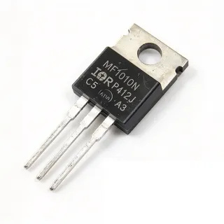
IRLB4030PBF - 100V 180A N-Channel HEXFET MOSFET | Infineon
Référence : IRLB4030PBF ✓ Actif| Qté | Prix unitaire | Total |
|---|---|---|
| 1 | $5.2 | $5,20 |
| 10 | $4.65 | $46,50 |
| 100 | $4.1 | $410,00 |
| 500 | $3.55 | $1 775,00 |
| 1 000 | $3.1 | $3 100,00 |
IRLB4030PBF Présentation
A power MOSFET (Metal-Oxide-Semiconductor Field-Effect Transistor) is a voltage-controlled three-terminal semiconductor switch used for switching and amplifying signals in electronic circuits. MOSFETs are the dominant switching element in modern power electronics because they combine high input impedance with low on-state conduction loss, fast switching speed, and excellent thermal performance. Within the broader taxonomy, the IRLB4030PBF sits in the N-channel enhancement-mode power MOSFET category, which falls under discrete semiconductors > transistors > MOSFETs, and is widely used as the low-side or high-side switch in DC-DC converters, motor drives, and synchronous rectification stages.
Key specifications include a drain-to-source breakdown voltage of 100 V, continuous drain current of 180 A at Tc, pulsed drain current capability beyond 180 A, ultra-low RDS(on) of 4.3 mOhm maximum at VGS=10 V, total gate charge of 87 nC, and a logic-level gate threshold compatible with 4.5 V drive. The TO-220AB package with a metal tab supports robust mechanical mounting and direct heatsink attachment for high-current applications.
The HEXFET process technology uses a hex-cell vertical DMOS structure that distributes current uniformly across the die, reducing localized hot spots and improving avalanche ruggedness. The IRLB4030PBF is specifically engineered for hard-switched and high-frequency circuits, where its low Qg and low RDS(on) product minimize conduction and switching losses simultaneously. Its logic-level gate drive simplifies interface to microcontrollers, gate drivers, and battery-powered systems.
Typical applications include DC motor drives, high-efficiency synchronous rectification in switched-mode power supplies (SMPS), uninterruptible power supplies (UPS), high-speed power switching converters, and hard-switched high-frequency circuits. The 100 V rating provides comfortable margin for 48 V telecom buses, battery-powered systems up to 60 V, and motor drives operating from rectified AC mains.
When designing with this device, ensure that VGS does not exceed +/-20 V absolute maximum, use a gate-source resistor of 10-100 ohm to dampen parasitic ringing, and provide adequate heatsinking for continuous operation above 50 A. The avalanche energy rating must be respected for unclamped inductive switching applications such as solenoid and motor drivers.
Alternatives de remplacement direct pour IRLB4030PBF — même boîtier, compatible broche à broche. Les références à boîtier différent nécessitant une retouche du PCB sont exclues.
Variantes de cette série
Modèles de la même série directement compatibles avec IRLB4030PBF (même facteur de forme et même empreinte) — différant par Package, Total Gate Charge (Qg), Technology, Operating Temperature Range, On-Resistance RDS(on) max at VGS=10V.
Outil de comparaison rapide — sélectionnez des références alternatives pour une comparaison côte à côte :
IRLB4030
✅ Remplacement direct📋 Alternative de référence (hors catalogue)
IRLB8748PBF
✅ Remplacement direct✓ En stock
$0.68 / unité
Voir la fiche technique →IRFB4310PBF
✅ Remplacement direct✓ En stock
$1.95 / unité
Voir la fiche technique →IRLR120NTRPBF
✅ Remplacement direct✓ En stock
$0.27 / unité
Voir la fiche technique →IRFR120NTRPBF
✅ Remplacement direct✓ En stock
$0.26 / unité
Voir la fiche technique →IRFZ48NSTRLPBF
✅ Remplacement direct✓ En stock
$1.18 / unité
Voir la fiche technique →IRLB4030PBF Valeurs maximales et caractéristiques électriques
| Type de transistor | N-Channel MOSFET |
| Drain-to-Source Voltage (VDS) | 100 V |
| Continuous Drain Current (ID) at Tc | 180 A |
| On-Resistance RDS(on) max at VGS=10V | 4.3 mOhm |
| Total Gate Charge (Qg) | 87 nC |
| Power Dissipation (PD) at Tc | 370 W |
| Plage de température de fonctionnement | -55C to +175C |
| Boîtier | TO-220AB |
| Type de montage | Through Hole |
| Technology | HEXFET (StrongIRFET family) |
| Logic Level Drive | Yes (optimized for 4.5 V to 10 V VGS) |
| Qualification | JEDEC |
| Statut RoHS | Compliant |
Configuration des broches de IRLB4030PBF
| Broche 1 | Gate — MOSFET gate drive input |
| Broche 2 | Drain — MOSFET drain (connected to metal tab) |
| Broche 3 | Source — MOSFET source return |
Zone de fonctionnement sûr (DC)
Applications typiques
IRLB4030PBF convient pour 6 applications: DC Motor Drive, Synchronous Rectification in SMPS, Uninterruptible Power Supply (UPS), High-Speed Power Switching, Solar Inverter Power Stage, Battery Management and Protection.
DC Motor Drive
The IRLB4030PBF is well suited for brushed DC motor drive circuits in industrial automation, robotics, and electric vehicle traction. Its 180 A continuous drain current at Tc and 4.3 mOhm RDS(on) deliver high torque with minimal conduction loss, while the 100 V VDS rating provides comfortable margin for 48 V battery packs and rectified 60 Vdc bus systems. The logic-level gate drive (4.5 V to 10 V) enables direct microcontroller PWM control at 1-25 kHz switching frequencies. Place a flyback diode across the motor terminals to protect against back-EMF; the device's avalanche ruggedness handles unclamped transients during PWM transitions.
Recommandé
Synchronous Rectification in SMPS
The IRLB4030PBF serves as a synchronous rectifier (SR) in switched-mode power supplies, replacing Schottky diodes in the secondary-side low-voltage stage. The 4.3 mOhm RDS(on) reduces conduction losses versus Schottky diodes by approximately 60-70%, significantly improving overall converter efficiency. At 180 A continuous current handling, it suits 1-3 kW telecom and server PSUs operating from 48 V input. The 87 nC total gate charge supports 100-500 kHz switching with appropriate gate driver selection. Infineon's StrongIRFET technology delivers the low Qgd/Qgs ratio required for clean switching transitions and reduced dead-time losses.
Recommandé
Uninterruptible Power Supply (UPS)
The IRLB4030PBF functions as the main switching element in UPS battery-to-AC inverter stages and DC bus converters. Its 100 V VDS rating accommodates 48 V and 60 V battery stacks with 30-40% voltage overshoot margin during transients. The 180 A continuous current capability supports 5-10 kVA single-phase UPS modules. The HEXFET process technology provides avalanche ruggedness critical for inductive load switching during battery transfer events. Heatsink attachment via the TO-220AB metal tab ensures continuous operation at high duty cycles, with 370 W power dissipation capability at maximum Tc.
Recommandé
High-Speed Power Switching
The IRLB4030PBF excels in hard-switched high-frequency applications including telecom DC-DC converters, Class D audio amplifiers, and pulse power circuits. With 87 nC Qg and 4.3 mOhm RDS(on), its figure-of-merit (FOM = RDS(on) x Qg = 0.37 Ohm-nC) enables efficient operation at switching frequencies up to 500 kHz. The logic-level gate drive simplifies interface with modern digital controllers. Designers should select gate drivers with 2-4 A peak source/sink capability to exploit the device's switching speed. The TO-220AB package provides low thermal resistance (approximately 1 C/W junction-to-case) for sustained high-current operation.
Recommandé
Solar Inverter Power Stage
The IRLB4030PBF is deployed in solar photovoltaic (PV) inverter power stages, where it operates as the low-side switch in boost converters and full-bridge inverter topologies. The 100 V VDS accommodates 48 V PV panel open-circuit voltages plus boost converter overshoot. The 180 A continuous current supports 5-10 kW residential and small-commercial string inverters. Logic-level gate drive simplifies bootstrap driver selection for high-side switches in the full-bridge configuration. The avalanche energy rating provides robustness during PV arc-fault and load-dump transient conditions common in outdoor installations.
Recommandé
Battery Management and Protection
The IRLB4030PBF acts as the high-current disconnect switch in lithium-ion battery management systems (BMS), providing safe isolation between battery packs and load circuits. Its 4.3 mOhm RDS(on) reduces I^2R losses during continuous high-current discharge, critical for 100+ Ah battery packs in e-mobility and energy storage. The 100 V VDS rating supports 48 V and 60 V battery architectures. Logic-level gate drive enables direct MOSFET control from the BMS controller. The HEXFET technology provides short-circuit withstand capability for fault-current interruption in protective disconnect applications.
Recommandé
Récapitulatif des produits recommandés
Données de référence d'ingénierie pour IRLB4030PBF — comparaison, recommandations de conception et informations de conformité.
Guide de sélection
Comparaison avec les alternatives
| Paramètre | Ce produit | IRLB4030 | IRLB8748PBF | IRFB4310PBF | IRLR120NTRPBF | IRFR120NTRPBF |
|---|---|---|---|---|---|---|
| Package | TO-220AB | TO-220AB - same | TO-220AB - same | TO-220AB - same | TO-220AB - same | TO-220AB - same |
| Brand | Infineon | Infineon | Infineon | Infineon | Infineon | Infineon |
| Drain-to-Source Voltage VDS max | 100 V | 100 V | 30 V | 100 V | 100 V | 100 V |
| Continuous Drain Current ID at Tc | 180 A | 180 A | 78 A | 140 A | 12 A | 9.4 A |
| On-Resistance RDS(on) max at VGS=10V | 4.3 mOhm | 4.3 mOhm | 4.8 mOhm | 7 mOhm | 180 mOhm | 220 mOhm |
| Total Gate Charge Qg | 87 nC | 87 nC | 44 nC | 120 nC | 20 nC | 25 nC |
| Power Dissipation PD at Tc | 370 W | 370 W | 89 W | 330 W | 40 W | 38 W |
| Logic-Level Gate Drive | Yes (4.5 V to 10 V VGS) | Yes | Yes | Yes | No (standard level) | No (standard level) |
Principaux différenciateurs
- 180 A continuous drain current at industry-leading 4.3 mOhm RDS(on) in TO-220AB (vs IRFB4310PBF)
- Logic-level gate drive compatible with 4.5 V to 10 V VGS (vs IRLR120NTRPBF)
- JEDEC-qualified StrongIRFET family with proven reliability (vs IRFR120NTRPBF)
Notes de conception
At 180 A continuous drain current, the IRLB4030PBF dissipates approximately P = I^2 x RDS(on) = 180^2 x 0.0043 = 139 W (worst case at maximum RDS(on)). A heatsink with thermal resistance below 0.5 C/W is required to keep junction temperature below 150 C in a 40 C ambient. Apply thermal compound (5-10 W/m-K conductivity) between the TO-220AB tab and heatsink. Estimated junction temperature rise: Tj = Ta + (PD x (RthJC + RthCS + RthSA)) where RthJC=0.4 C/W typical, RthCS=0.5 C/W with thermal compound, RthSA=0.5 C/W for a quality heatsink. Verify Tj stays below 175 C maximum.
Do not exceed VGS absolute maximum of +/-20 V; gate-source ESD damage is a common failure mode when the gate is left floating. Always include a 10 kOhm gate-source resistor to ensure the MOSFET stays off during power-up and resists dv/dt-induced turn-on. For inductive loads (motors, solenoids, transformers), place a flyback diode or TVS across the drain-source to clamp back-EMF; the avalanche energy rating is finite. Estimated safe unclamped avalanche energy depends on drain current at turn-off and inductance; consult the datasheet for EAS curves.
For high-current switching circuits, minimize parasitic inductance in the power loop (drain-source loop). Use wide copper pours (at least 4 oz or 100 um thickness) on the drain and source traces, and keep the loop area under 100 mm^2 to limit voltage spikes during turn-off. Place the gate driver within 25 mm of the gate pin to minimize gate-loop inductance. A 10-100 ohm gate resistor dampens ringing; an optional 10 kOhm gate-source pull-down prevents floating-gate turn-on during system startup.
Informations de conformité
RoHS and REACH compliant per Infineon product page. The 'PBF' suffix designates lead-free plating. Not AEC-Q100 qualified - for automotive applications, refer to Infineon automotive-grade StrongIRFET portfolio.