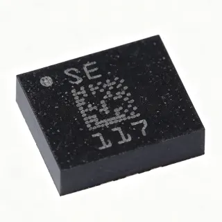
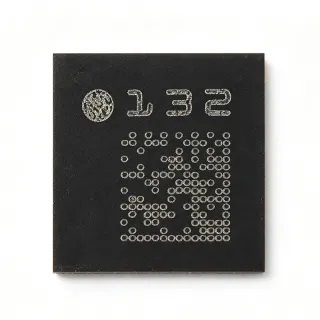
MMA9555LR1 - 3-Axis Intelligent Motion-Sensing Pedometer | NXP
Référence : MMA9555LR1 ✓ Actif| Qté | Prix unitaire | Total |
|---|---|---|
| 1 | $4.95 | $4,95 |
| 10 | $4.46 | $44,60 |
| 100 | $3.96 | $396,00 |
| 500 | $3.56 | $1 780,00 |
| 1 000 | $3.16 | $3 160,00 |
MMA9555LR1 Présentation
An intelligent motion-sensing pedometer is a system-in-package that fuses a MEMS accelerometer with an onboard microcontroller executing step-detection algorithms, freeing the host processor from continuous polling. The MMA9555LR1 belongs to the broader hierarchy of accelerometer -> motion sensor -> inertial measurement unit -> MEMS sensor -> semiconductor device. By integrating the algorithm in hardware, these platforms reduce host-side firmware burden, lower average current, and improve step-count fidelity versus raw-accelerometer designs.
Key features of the MMA9555LR1 include selectable g-ranges (2 g/4 g/8 g), built-in 32-bit microcontroller, auto-wake and auto-sleep functions for power savings, and a digital I2C/SPI-compatible interface. The device's high sensitivity (16393 LSB/g at +/-2 g) provides fine motion resolution suitable for activity classification and pedometer applications.
Architecturally, the MMA9555LR1 couples a capacitive MEMS sense element with a signal-conditioning ASIC and embedded ColdFire microcontroller, executing on-chip step-counting and activity-level algorithms. The 3-axis accelerometer data is sampled internally, filtered, and processed before being passed to the host, reducing I2C/SPI bus traffic and overall system power consumption.
Typical applications include wearable fitness bands, pedometers, mobile handsets, activity monitors, and portable consumer electronics. In fitness bands, the part's auto-wake and auto-sleep features extend battery life by powering down the sensor between active periods while still capturing steps during sleep.
When designing with this device, ensure adequate decoupling on VDD (typically 100 nF ceramic close to the supply pin) and follow the layout guidelines in the NXP datasheet to minimize noise coupling into the MEMS element. Use the device's interrupt and auto-wake features to minimize host-controller duty cycle and maximize battery life in wearable designs.
Alternatives de remplacement direct pour MMA9555LR1 — même boîtier, compatible broche à broche. Les références à boîtier différent nécessitant une retouche du PCB sont exclues.
Variantes de cette série
Modèles de la même série directement compatibles avec MMA9555LR1 (même facteur de forme et même empreinte) — différant par Acceleration Range, Interface, Output Type, Package, Type.
Outil de comparaison rapide — sélectionnez des références alternatives pour une comparaison côte à côte :
MMA9553LR1
✅ Remplacement direct✓ En stock
$3.21 / unité
Voir la fiche technique →MMA9550LR1
✅ Remplacement direct📋 Alternative de référence (hors catalogue)
MMA8451QR1
✅ Remplacement direct📋 Alternative de référence (hors catalogue)
MMA9555LR1 Valeurs maximales et caractéristiques électriques
| Type | Digital Accelerometer |
| Axis | X, Y, Z (3-axis) |
| Acceleration Range | +/-2 g, +/-4 g, +/-8 g (selectable) |
| Sensitivity (+/-2 g) | 16393 LSB/g |
| Sensitivity (+/-4 g) | 8196 LSB/g |
| Sensitivity (+/-8 g) | 4098 LSB/g |
| Tension d'alimentation | 1.8 V |
| Interface | I2C / SPI (digital) |
| Type de sortie | Digital |
| Integrated MCU | 32-bit microcontroller (on-chip) |
| Power Features | Auto wake / Auto sleep |
| Fonction | Intelligent motion-sensing pedometer with activity level |
| Boîtier | 16-pin LGA |
| Type de montage | Surface Mount |
| Packaging | Tape & Reel (TR) |
Configuration des broches de MMA9555LR1
| Broche 1 | VDD — Power supply (1.8 V) |
| Broche 2 | GND — Ground |
| Broche 3 | SDA — I2C data / SPI data |
| Broche 4 | SCL — I2C clock / SPI clock |
| Broche 5 | INT1 — Interrupt output 1 |
| Broche 6 | INT2 — Interrupt output 2 |
| Broche 7 | CS — SPI chip select |
| Broche 8 | RESET — Reset input |
| Broche 9 | GND — Ground |
| Broche 10 | GND — Ground |
| Broche 11 | GND — Ground |
| Broche 12 | GND — Ground |
| Broche 13 | NC — Not connected (per datasheet) |
| Broche 14 | NC — Not connected (per datasheet) |
| Broche 15 | NC — Not connected (per datasheet) |
| Broche 16 | NC — Not connected (per datasheet) |
Applications typiques
MMA9555LR1 convient pour 6 applications: Wearable Fitness Bands, Smartphone Pedometer, Activity Monitors, Portable Consumer Electronics, Wrist-Worn Health Devices, Mobile Phone Motion Coprocessor.
Wearable Fitness Bands
The MMA9555LR1's integrated 32-bit MCU and on-chip pedometer algorithm make it ideal for wearable fitness bands where battery life and host MIPS budget are critical constraints. The part operates from a 1.8 V supply compatible with typical wearable PMIC rails, and the selectable +/-2 g/+/-4 g/+/-8 g ranges with sensitivities up to 16393 LSB/g at +/-2 g provide fine step-detection resolution. Auto-wake and auto-sleep functions further reduce average current consumption by powering down the sensor between motion events. In a fitness band design, the MMA9555LR1 sits on a dedicated I2C bus to the host BLE SoC, reporting step counts and activity levels without continuous raw-data streaming. Unlike raw accelerometers that require host-side processing, the MMA9555LR1 offloads algorithm execution to its embedded ColdFire MCU, freeing the host for radio and display tasks.
Recommandé
Smartphone Pedometer
The MMA9555LR1 enables dedicated pedometer functionality in smartphones, offloading step-counting from the main application processor to extend battery life. Per the NXP datasheet, the integrated MCU runs activity-level classification algorithms and reports summarized results to the host, reducing I2C/SPI bus traffic by orders of magnitude compared to streaming raw accelerometer data. The 16-pin LGA footprint occupies minimal PCB area, suitable for compact handset designs. Operating from 1.8 V makes it directly compatible with the typical smartphone PMIC output rail. Designers can pair the MMA9555LR1 with the host AP via I2C, using the auto-wake feature to wake the application processor only when significant motion is detected, further reducing system power consumption.
Recommandé
Activity Monitors
The MMA9555LR1's selectable g-ranges and on-chip activity classification make it suitable for activity monitors that need to distinguish walking, running, and stationary states. The +/-8 g range at 4098 LSB/g sensitivity supports high-motion activities like running, while the +/-2 g range at 16393 LSB/g captures subtle motion during walking. Per NXP documentation, the integrated 32-bit MCU executes activity-level algorithms, allowing the host processor to read pre-classified activity data rather than raw acceleration. The 1.8 V supply and low-power auto-sleep mode enable multi-day battery life in activity monitor form factors. The 16-pin LGA footprint and Tape & Reel packaging support high-volume SMT manufacturing.
Recommandé
Portable Consumer Electronics
The MMA9555LR1 brings pedometer and motion-sensing capability to portable consumer products without consuming host processor resources. The integrated 32-bit ColdFire MCU handles step-detection and activity-classification algorithms internally, so the host application processor stays in low-power state until meaningful motion events occur. Per the NXP datasheet, auto-wake and auto-sleep features reduce average current draw to a fraction of continuous-sampling designs. The 16-pin LGA package occupies minimal PCB real estate, valuable for compact portable form factors. The 1.8 V supply is compatible with common portable PMIC rails, simplifying power tree design.
Recommandé
Wrist-Worn Health Devices
The MMA9555LR1's compact 16-pin LGA package and 1.8 V supply make it suitable for wrist-worn health devices where board area is constrained and battery life is critical. Per the NXP datasheet, the part's auto-sleep mode drops current consumption to microampere levels between motion events, while auto-wake instantly resumes sensing on detected activity. The selectable +/-2 g/+/-4 g/+/-8 g ranges support different user activity intensities, with +/-2 g at 16393 LSB/g providing the granular step-counting resolution needed for fitness tracking. The integrated MCU offloads algorithm execution from the host, extending device battery life in wrist-worn form factors.
Recommandé
Mobile Phone Motion Coprocessor
In mobile phone architectures, the MMA9555LR1 serves as a dedicated motion coprocessor that offloads pedometer and activity-recognition tasks from the main application processor. The integrated 32-bit MCU executes step-counting and activity-classification algorithms, reporting results via I2C or SPI rather than streaming raw samples, reducing bus traffic and host-side MIPS consumption. The 1.8 V supply matches typical mobile PMIC outputs. Per the NXP datasheet, the auto-wake feature can wake the application processor only on significant motion, supporting deep sleep modes that extend phone standby time. The 16-pin LGA footprint fits in compact handset layouts.
Recommandé
Récapitulatif des produits recommandés
Données de référence d'ingénierie pour MMA9555LR1 — comparaison, recommandations de conception et informations de conformité.
Guide de sélection
Comparaison avec les alternatives
| Paramètre | Ce produit | MMA9553LR1 | MMA9550LR1 | MMA8451QR1 |
|---|---|---|---|---|
| Package | 16-pin LGA | 16-pin LGA - same | 16-pin LGA - same | 16-pin QFN - same pin count |
| Brand | NXP Semiconductors | NXP Semiconductors | NXP Semiconductors | NXP Semiconductors |
| Type | Intelligent motion-sensing pedometer with MCU | Intelligent tilt-sensing platform with MCU | Intelligent motion-sensing platform base | Raw digital accelerometer (no MCU) |
| Axis | X, Y, Z | X, Y, Z | X, Y, Z | X, Y, Z |
| Acceleration Range | +/-2 g, +/-4 g, +/-8 g | +/-2 g, +/-4 g, +/-8 g | +/-2 g, +/-4 g, +/-8 g | +/-2 g, +/-4 g, +/-8 g |
| Sensitivity (+/-2 g) | 16393 LSB/g | 16393 LSB/g (typical same family) | 16393 LSB/g (typical same family) | 4096 LSB/g (14-bit raw) |
| Supply Voltage | 1.8 V | 1.8 V | 1.8 V | 1.95 V to 3.6 V |
| Interface | I2C / SPI | I2C / SPI | I2C / SPI | I2C |
| Integrated MCU | Yes (32-bit, pedometer algorithms) | Yes (32-bit, tilt algorithms) | Yes (32-bit, configurable) | No (raw accelerometer) |
| Auto Wake / Auto Sleep | Yes | Yes | Yes | No (host-managed) |
Principaux différenciateurs
- Integrated 32-bit MCU with on-chip pedometer algorithm (vs MMA8451QR1)
- Purpose-built for pedometer accuracy (vs MMA9553LR1)
- Auto wake/auto sleep power management (vs MMA9550LR1)
Notes de conception
Estimated: at 1.8 V supply and using the auto-wake/auto-sleep features, average current consumption can drop to a few microamperes between motion events. Decouple the supply with a 100 nF ceramic capacitor placed within 3 mm of the VDD pin, plus a bulk 1 uF capacitor to handle transient current spikes during active sampling. Ensure the 1.8 V rail is low-noise; ripple above 50 mVpk-pk can couple into the MEMS element and bias step-counting decisions.
Place the MMA9555LR1 on a stable, vibration-isolated section of the PCB away from motors, speakers, and other vibration sources that could inject false motion events. The LGA package has an exposed pad that must be soldered to a grounded copper pour for mechanical stability and thermal dissipation. Keep high-current traces and switched-power components away from the sensor to minimize EMI coupling. Follow NXP's recommended PCB footprint and reflow profile from the MMA9555L datasheet.
Do not stream raw accelerometer data continuously to the host - this defeats the purpose of the integrated MCU and wastes bus bandwidth and host MIPS. Use the device's interrupt output (INT1/INT2) to wake the host only when meaningful motion events occur. Avoid mounting the part near heat sources or in direct sunlight, as thermal gradients can shift MEMS zero-g offset and degrade accuracy. The on-chip pedometer algorithm is tuned for human walking; do not expect accurate step counts for cycling or driving.
Keep I2C/SPI traces short (under 50 mm) and route them over a continuous ground plane to minimize EMI pickup. Place 4.7 kohm pull-up resistors on SDA and SCL close to the host side if using I2C. For SPI, ensure the chip-select (CS) line is properly managed to avoid bus contention. If the sensor must be placed near RF sources (BLE antenna, Wi-Fi module), add ground stitching vias around the sensor footprint to shield against radiated interference.
Informations de conformité
RoHS and lead-free compliance per NXP product page. Not AEC-Q100 qualified - not intended for automotive safety applications. Halogen-free status not explicitly stated in provided data.