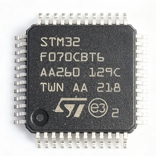
STM32F070CBT6 - ARM Cortex-M0 MCU 128KB Flash | STMicroelectronics
Référence : STM32F070CBT6 ✓ Actif| Qté | Prix unitaire | Total |
|---|---|---|
| 1 | $3.58 | $3,58 |
| 10 | $2.31 | $23,10 |
| 100 | $1.83 | $183,00 |
| 500 | $1.69 | $845,00 |
| 1 000 | $1.6 | $1 600,00 |
| 1 500 | $1.57 | $2 355,00 |
STM32F070CBT6 Présentation
What is a microcontroller? A microcontroller (MCU) is a compact integrated circuit designed to govern a specific operation in an embedded system. It integrates a processor core, memory (Flash and SRAM), and programmable input/output peripherals on a single chip. The STM32F070CBT6 belongs to the STM32F0 series, which is part of the broader STM32 family of 32-bit ARM Cortex-M microcontrollers. This hierarchy places it within the ARM Cortex-M0 category, a low-power, entry-level core optimized for cost-sensitive applications.
Key features include a 12-bit ADC with up to 16 channels, multiple communication interfaces (I2C, SPI, USART), and a variety of timers including advanced-control timers. The device also includes a DMA controller, an RTC, and a CRC calculation unit. The LQFP-48 package provides a compact footprint suitable for space-constrained designs while offering sufficient I/O pins for peripheral connectivity.
The STM32F070CBT6 is built on a 32-bit ARM Cortex-M0 core with a Harvard architecture, achieving 1.25 DMIPS/MHz. It includes a nested vectored interrupt controller (NVIC) for efficient interrupt handling and supports both low-power modes (Sleep, Stop, Standby) to optimize energy consumption. The device is designed for a wide range of embedded applications requiring a balance of performance, power efficiency, and cost.
Typical applications include industrial control systems, consumer electronics, IoT devices, and home automation. Its rich peripheral set and low-power capabilities make it suitable for sensor interfacing, motor control, and communication protocols. The wide operating temperature range (-40°C to +85°C) ensures reliability in harsh environments.
When designing with this MCU, ensure proper decoupling of the power supply pins and consider the use of an external crystal for accurate timing. The device supports in-circuit programming and debugging via SWD, facilitating firmware development and updates.
This page synthesizes distributor pricing, drop-in alternatives, and practical design notes not found in the STMicroelectronics datasheet, providing engineers with a comprehensive resource for selection and implementation.
Alternatives de remplacement direct pour STM32F070CBT6 — même boîtier, compatible broche à broche. Les références à boîtier différent nécessitant une retouche du PCB sont exclues.
Outil de comparaison rapide — sélectionnez des références alternatives pour une comparaison côte à côte :
STM32F071CBT6
📋 Alternative de référence (hors catalogue)
STM32F072CBT6
📋 Alternative de référence (hors catalogue)
STM32F078CBT6
📋 Alternative de référence (hors catalogue)
STM32F070CBT6 Valeurs maximales et caractéristiques électriques
| Core | ARM Cortex-M0 |
| Core Frequency | 48 MHz |
| Flash Memory | 128 KB |
| SRAM | 16 KB |
| Tension d'alimentation | 2.4 V to 3.6 V |
| Boîtier | LQFP-48 |
| Température de fonctionnement | -40°C to +85°C |
| ADC | 12-bit, 16 channels |
| Communication Interfaces | I2C, SPI, USART |
| Timers | Advanced-control, general-purpose, basic |
| DMA | Yes, 5 channels |
| RTC | Yes |
| CRC | Yes |
| Low-Power Modes | Sleep, Stop, Standby |
| Debug Interface | SWD |
| Statut RoHS | Compliant |
Configuration des broches de STM32F070CBT6
| Broche 1 | VBAT — Battery backup supply for RTC |
| Broche 2 | PC13 — GPIO / RTC tamper |
| Broche 3 | PC14 — GPIO / OSC32_IN |
| Broche 4 | PC15 — GPIO / OSC32_OUT |
| Broche 5 | PF0 — GPIO / OSC_IN |
| Broche 6 | PF1 — GPIO / OSC_OUT |
| Broche 7 | NRST — Reset (active low) |
| Broche 8 | VSSA — Analog ground |
| Broche 9 | VDDA — Analog power supply |
| Broche 10 | PA0 — GPIO / ADC_IN0 / USART2_CTS |
| Broche 11 | PA1 — GPIO / ADC_IN1 / USART2_RTS |
| Broche 12 | PA2 — GPIO / ADC_IN2 / USART2_TX |
| Broche 13 | PA3 — GPIO / ADC_IN3 / USART2_RX |
| Broche 14 | PA4 — GPIO / ADC_IN4 / SPI1_NSS |
| Broche 15 | PA5 — GPIO / ADC_IN5 / SPI1_SCK |
| Broche 16 | PA6 — GPIO / ADC_IN6 / SPI1_MISO |
| Broche 17 | PA7 — GPIO / ADC_IN7 / SPI1_MOSI |
| Broche 18 | PB0 — GPIO / ADC_IN8 / TIM3_CH3 |
| Broche 19 | PB1 — GPIO / ADC_IN9 / TIM3_CH4 |
| Broche 20 | PB2 — GPIO / BOOT1 |
| Broche 21 | PB10 — GPIO / I2C2_SCL / USART3_TX |
| Broche 22 | PB11 — GPIO / I2C2_SDA / USART3_RX |
| Broche 23 | PB12 — GPIO / SPI2_NSS / I2C2_SMBA |
| Broche 24 | PB13 — GPIO / SPI2_SCK / USART3_CTS |
| Broche 25 | PB14 — GPIO / SPI2_MISO / USART3_RTS |
| Broche 26 | PB15 — GPIO / SPI2_MOSI |
| Broche 27 | PC6 — GPIO / TIM3_CH1 |
| Broche 28 | PC7 — GPIO / TIM3_CH2 |
| Broche 29 | PC8 — GPIO / TIM3_CH3 |
| Broche 30 | PC9 — GPIO / TIM3_CH4 |
| Broche 31 | PA8 — GPIO / MCO / TIM1_CH1 |
| Broche 32 | PA9 — GPIO / USART1_TX / TIM1_CH2 |
| Broche 33 | PA10 — GPIO / USART1_RX / TIM1_CH3 |
| Broche 34 | PA11 — GPIO / USART1_CTS / CAN_RX |
| Broche 35 | PA12 — GPIO / USART1_RTS / CAN_TX |
| Broche 36 | PA13 — GPIO / SWDIO |
| Broche 37 | VSS — Ground |
| Broche 38 | VDD — Power supply |
| Broche 39 | PA14 — GPIO / SWCLK |
| Broche 40 | PA15 — GPIO / TIM2_CH1 / SPI1_NSS |
| Broche 41 | PB3 — GPIO / TIM2_CH2 / SPI1_SCK |
| Broche 42 | PB4 — GPIO / TIM3_CH1 / SPI1_MISO |
| Broche 43 | PB5 — GPIO / TIM3_CH2 / SPI1_MOSI |
| Broche 44 | PB6 — GPIO / I2C1_SCL / TIM1_CH3 |
| Broche 45 | PB7 — GPIO / I2C1_SDA / TIM1_CH4 |
| Broche 46 | BOOT0 — Boot mode selection |
| Broche 47 | PB8 — GPIO / I2C1_SCL / CAN_RX |
| Broche 48 | PB9 — GPIO / I2C1_SDA / CAN_TX |
Applications typiques
STM32F070CBT6 convient pour 6 applications: Industrial Control, Consumer Electronics, IoT Devices, Home Automation, Sensor Interfacing, Motor Control.
Industrial Control
The STM32F070CBT6 is well-suited for industrial control systems due to its robust peripheral set, including advanced timers for PWM generation, multiple USARTs for communication with PLCs, and a 12-bit ADC for sensor feedback. Its wide operating temperature range (-40°C to +85°C) ensures reliable operation in factory environments. In a typical motor control application, the MCU generates PWM signals to drive an H-bridge, reads current and position sensors via the ADC, and communicates status over RS-485. The 48 MHz Cortex-M0 core provides sufficient processing power for real-time control loops, while the DMA controller offloads data transfer to reduce CPU load. The low-power modes allow energy savings during idle periods, making it suitable for energy-efficient industrial equipment.
Recommandé
Consumer Electronics
In consumer electronics, the STM32F070CBT6 provides a cost-effective solution for devices like smart home controllers, remote controls, and small appliances. Its low power consumption and multiple communication interfaces (I2C, SPI, USART) enable seamless integration with sensors, displays, and wireless modules. For example, in a smart thermostat, the MCU reads temperature and humidity sensors via I2C, controls a relay for heating/cooling, and communicates with a Wi-Fi module over UART. The 128KB Flash is ample for firmware implementing user interfaces and connectivity protocols. The LQFP-48 package is compact enough for sleek product designs, and the wide supply voltage range (2.4V-3.6V) allows direct battery operation. The device's low-power modes extend battery life in portable consumer devices.
Recommandé
IoT Devices
The STM32F070CBT6 is an excellent choice for IoT edge nodes due to its balance of performance, power efficiency, and cost. It supports various communication protocols (UART, SPI, I2C) to interface with sensors and wireless transceivers. In a typical IoT sensor node, the MCU periodically wakes from Stop mode to read sensor data, process it, and transmit via a LoRa or BLE module. The 12-bit ADC with 16 channels allows multiple analog sensors to be connected directly. The DMA controller enables efficient data transfer without CPU intervention, reducing power consumption. The device's low-power Standby mode (1 µA typical) is critical for battery-powered deployments. With 128KB Flash, developers can implement robust firmware including over-the-air update capabilities.
Recommandé
Home Automation
The STM32F070CBT6 is ideal for home automation hubs and smart devices. Its multiple UARTs and I2C interfaces allow connection to various sensors and actuators, while its low-power modes enable always-on operation with minimal energy consumption. In a smart lighting system, the MCU controls LED drivers via PWM, reads ambient light sensors, and communicates with a central hub over Zigbee or Wi-Fi. The 48 MHz core handles protocol stacks efficiently, and the 128KB Flash accommodates complex automation logic. The device's wide operating temperature range ensures reliable operation in residential environments. The LQFP-48 package is suitable for compact wall-mounted modules, and the SWD debug interface simplifies firmware development and updates.
Recommandé
Sensor Interfacing
The STM32F070CBT6 excels in sensor interfacing applications due to its rich analog and digital peripherals. The 12-bit ADC with 16 channels can directly connect multiple analog sensors, while I2C and SPI interfaces support digital sensors. In a data acquisition system, the MCU samples temperature, pressure, and flow sensors, processes the data, and transmits it to a host via USART. The DMA controller allows continuous ADC sampling without CPU overhead, ensuring accurate data capture. The device's low-power modes are beneficial for remote sensor nodes powered by batteries. The 128KB Flash provides ample space for calibration tables and data logging. The wide supply voltage range accommodates various sensor supply requirements.
Recommandé
Motor Control
The STM32F070CBT6 is well-suited for motor control applications, particularly for brushless DC (BLDC) and stepper motors. Its advanced-control timers can generate complementary PWM signals with dead-time insertion, essential for driving H-bridges. The 12-bit ADC enables precise current sensing, and the DMA controller facilitates high-speed data transfer. In a BLDC motor controller, the MCU reads Hall sensor inputs, generates six-step commutation signals, and regulates speed via PID control. The 48 MHz core provides sufficient computational power for real-time control loops. The device's robust timer architecture and fault handling features ensure safe operation. The LQFP-48 package is compact enough for integrated motor drivers, and the wide temperature range supports industrial motor applications.
Recommandé
Récapitulatif des produits recommandés
Données de référence d'ingénierie pour STM32F070CBT6 — comparaison, recommandations de conception et informations de conformité.
Guide de sélection
Comparaison avec les alternatives
| Paramètre | Ce produit | STM32F071CBT6 | STM32F072CBT6 | STM32F078CBT6 |
|---|---|---|---|---|
| Package | LQFP-48 | LQFP-48 - same | LQFP-48 - same | LQFP-48 - same |
| Core Frequency | 48 MHz | 48 MHz | 48 MHz | 48 MHz |
| Flash Memory | 128 KB | 128 KB | 128 KB | 128 KB |
| SRAM | 16 KB | 16 KB | 16 KB | 16 KB |
| USB | Yes (full-speed device) | Yes (full-speed device) | Yes (full-speed device) | Yes (full-speed device) |
| CAN | No | No | Yes | Yes |
| DAC | No | Yes (12-bit) | Yes (12-bit) | Yes (12-bit) |
| Comparator | No | Yes | Yes | Yes |
| Price (1k) | $2.20 | $2.40 | $2.60 | $2.80 |
Principaux différenciateurs
- USB full-speed device controller (vs STM32F030CBT6)
- Lower cost than F071/F072 (vs STM32F071CBT6)
- Pin-to-pin compatible with higher-feature siblings (vs STM32F072CBT6)
Notes de conception
Decouple the VDD and VDDA pins with 100nF ceramic capacitors placed as close to the pins as possible. Additionally, add a 4.7uF bulk capacitor on the main VDD rail. For VDDA, use a ferrite bead in series to filter high-frequency noise, improving ADC accuracy.
For the LQFP-48 package, ensure proper solder paste stencil design with 0.5mm pitch. Use a 4-layer PCB with a solid ground plane beneath the MCU to reduce EMI and improve thermal performance. Route high-speed signals (SPI, USART) with controlled impedance if possible.
Do not leave unused GPIO pins floating; configure them as outputs or enable internal pull-ups/pull-downs to avoid excessive current consumption. Also, ensure the BOOT0 pin is properly pulled low for normal boot from Flash. For low-power modes, disable unused peripherals and clocks to achieve specified current consumption.
Informations de conformité
RoHS and REACH compliant per STMicroelectronics. Not AEC-Q100 qualified; for automotive, consider STM32F0 series with AEC-Q100 option.


