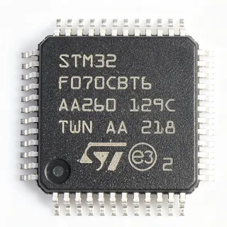
STM8AF6388 - 8-bit Automotive MCU, 64KB Flash | STMicroelectronics
Référence : STM8AF6388 ✓ Actif| Qté | Prix unitaire | Total |
|---|---|---|
| 1 | $3.85 | $3,85 |
| 10 | $3.47 | $34,70 |
| 100 | $3.08 | $308,00 |
| 500 | $2.77 | $1 385,00 |
| 1 000 | $2.46 | $2 460,00 |
STM8AF6388 Présentation
An 8-bit microcontroller (MCU) is a single-chip computer with an 8-bit central processing unit (CPU), memory, and programmable input/output peripherals. It is a subset of the broader microcontroller family, which falls under embedded systems and integrated circuits. The STM8A core is an enhanced 8-bit architecture with a three-stage pipeline, delivering up to 16 MIPS at 24 MHz, making it suitable for real-time control applications.
Key features include 64KB of Flash memory with read-while-write capability, 6KB of SRAM, and 2KB of EEPROM with true data EEPROM. It integrates a 10-bit ADC with up to 16 channels, two 16-bit timers, one 8-bit timer, and a CAN 2.0B controller for automotive networking. The device also includes an SPI, I2C, and two UARTs for communication, along with a LIN interface for local interconnect networking.
The STM8AF6388 is built on a high-density Flash technology, providing robust data retention and endurance. The automotive qualification (AEC-Q100) ensures reliability under extreme temperature and vibration conditions. The CAN controller supports both standard and extended frame formats, enabling seamless integration into vehicle networks.
Typical applications include body control modules, automotive lighting control, sensor interfaces, and power window control. The device's low power consumption and wide voltage range make it ideal for battery-powered automotive systems. Its robust communication interfaces allow it to serve as a central node in distributed automotive networks.
When designing with this MCU, ensure proper decoupling of the power supply pins and use the internal RC oscillator for cost-sensitive designs, or an external crystal for higher accuracy. The CAN bus requires proper termination resistors and common-mode chokes for EMC compliance.
Alternatives de remplacement direct pour STM8AF6388 — même boîtier, compatible broche à broche. Les références à boîtier différent nécessitant une retouche du PCB sont exclues.
Outil de comparaison rapide — sélectionnez des références alternatives pour une comparaison côte à côte :
STM8AF6288
✅ Remplacement direct ⚠️ Spécifications non vérifiées📋 Alternative de référence (hors catalogue)
STM8AF5288
✅ Remplacement direct ⚠️ Spécifications non vérifiées📋 Alternative de référence (hors catalogue)
STM8AF6389
✅ Remplacement direct ⚠️ Spécifications non vérifiées📋 Alternative de référence (hors catalogue)
R5F10AGF
✅ Remplacement direct ⚠️ Spécifications non vérifiées📋 Alternative de référence (hors catalogue)
STM8AF6388 Valeurs maximales et caractéristiques électriques
| Core | STM8A 8-bit |
| Fréquence d'horloge maximale | 24 MHz |
| Flash Memory | 64 KB |
| SRAM | 6 KB |
| EEPROM | 2 KB |
| Tension d'alimentation | 3.0 V to 5.5 V |
| Température de fonctionnement | -40C to +150C |
| Boîtier | LQFP-48 |
| ADC Resolution | 10-bit |
| ADC Channels | 16 |
| Timers | 2x 16-bit, 1x 8-bit |
| CAN Interface | 2.0B |
| SPI | 1 |
| I2C | 1 |
| UART | 2 |
| LIN | 1 |
| GPIO Pins | 38 |
| AEC-Q100 | Qualified |
| RoHS | Compliant |
Configuration des broches de STM8AF6388
| Broche 1 | VSS — Ground |
| Broche 2 | VDD — Power supply |
| Broche 3 | PA0 — GPIO/ADC |
| Broche 4 | PA1 — GPIO/ADC |
| Broche 5 | PA2 — GPIO/ADC |
| Broche 6 | PA3 — GPIO/ADC |
| Broche 7 | NRST — Reset |
| Broche 8 | PA4 — GPIO/ADC |
| Broche 9 | PA5 — GPIO/ADC |
| Broche 10 | PA6 — GPIO/ADC |
| Broche 11 | PA7 — GPIO/ADC |
| Broche 12 | PB0 — GPIO |
| Broche 13 | PB1 — GPIO |
| Broche 14 | PB2 — GPIO |
| Broche 15 | PB3 — GPIO |
| Broche 16 | PB4 — GPIO |
| Broche 17 | PB5 — GPIO |
| Broche 18 | PB6 — GPIO |
| Broche 19 | PB7 — GPIO |
| Broche 20 | PC0 — GPIO/ADC |
| Broche 21 | PC1 — GPIO/ADC |
| Broche 22 | PC2 — GPIO/ADC |
| Broche 23 | PC3 — GPIO/ADC |
| Broche 24 | PC4 — GPIO/ADC |
| Broche 25 | PC5 — GPIO/ADC |
| Broche 26 | PC6 — GPIO/ADC |
| Broche 27 | PC7 — GPIO/ADC |
| Broche 28 | PD0 — GPIO |
| Broche 29 | PD1 — GPIO |
| Broche 30 | PD2 — GPIO |
| Broche 31 | PD3 — GPIO |
| Broche 32 | PD4 — GPIO |
| Broche 33 | PD5 — GPIO |
| Broche 34 | PD6 — GPIO |
| Broche 35 | PD7 — GPIO |
| Broche 36 | PE0 — GPIO |
| Broche 37 | PE1 — GPIO |
| Broche 38 | PE2 — GPIO |
| Broche 39 | PE3 — GPIO |
| Broche 40 | PE4 — GPIO |
| Broche 41 | PE5 — GPIO |
| Broche 42 | PE6 — GPIO |
| Broche 43 | PE7 — GPIO |
| Broche 44 | VDD — Power supply |
| Broche 45 | VSS — Ground |
| Broche 46 | PF0 — GPIO/ADC |
| Broche 47 | PF1 — GPIO/ADC |
| Broche 48 | PF2 — GPIO/ADC |
Applications typiques
STM8AF6388 convient pour 6 applications: Automotive Body Control Module, Automotive Lighting Control, Sensor Interface, Power Window Control, Electric Power Steering (EPS) Auxiliary, Industrial Automation.
Automotive Body Control Module
The STM8AF6388 is ideal for body control modules (BCM) due to its CAN interface, 64KB Flash for complex algorithms, and AEC-Q100 qualification. It manages lighting, wipers, and door locks, communicating over the CAN bus. The 10-bit ADC reads sensor inputs, while timers generate PWM for motor control. Its wide voltage range (3.0-5.5V) allows direct battery connection, and the low power modes extend battery life. The robust temperature range (-40 to +150°C) ensures operation in harsh automotive environments.
Recommandé
Automotive Lighting Control
The STM8AF6388 controls LED headlights and taillights with PWM outputs from its timers. The 10-bit ADC monitors current sense resistors for fault detection. Its CAN interface allows synchronization with other vehicle modules. The 64KB Flash stores calibration tables and diagnostic routines. The device's high temperature rating is essential for under-hood lighting applications. The EEPROM stores non-volatile settings like brightness levels.
Recommandé
Sensor Interface
The STM8AF6388 interfaces with various automotive sensors (temperature, pressure, position) via its 16-channel 10-bit ADC. The SPI and I2C interfaces connect to digital sensors. The UARTs support diagnostic communication. Its low power consumption is critical for always-on sensor monitoring. The 64KB Flash allows complex signal processing algorithms. The AEC-Q100 qualification ensures reliability in vibration-prone environments.
Recommandé
Power Window Control
The STM8AF6388 controls power window motors using PWM from its timers. The 10-bit ADC monitors motor current for anti-pinch detection. The CAN interface allows central locking integration. Its 64KB Flash stores window position calibration and safety algorithms. The device's robust I/O handles direct motor drive via external H-bridge. The wide voltage range accommodates battery voltage fluctuations during cranking.
Recommandé
Electric Power Steering (EPS) Auxiliary
The STM8AF6388 can serve as a secondary controller in EPS systems, handling torque sensor inputs and providing redundancy. Its 10-bit ADC reads torque and angle sensors. The CAN interface communicates with the main EPS ECU. The 64KB Flash stores diagnostic and calibration data. The high temperature rating is suitable for under-hood mounting. The device's deterministic timing ensures reliable real-time control.
Recommandé
Industrial Automation
Beyond automotive, the STM8AF6388 is used in industrial automation for motor control and sensor monitoring. Its CAN interface supports industrial networks. The 10-bit ADC and timers enable precise control. The wide voltage range and temperature tolerance make it suitable for factory floor environments. The 64KB Flash allows complex control algorithms. The device's robustness reduces field failures.
Recommandé
Récapitulatif des produits recommandés
Données de référence d'ingénierie pour STM8AF6388 — comparaison, recommandations de conception et informations de conformité.
Guide de sélection
Comparaison avec les alternatives
| Paramètre | Ce produit | STM8AF6288 | STM8AF5288 | STM8AF6389 | R5F10AGF |
|---|---|---|---|---|---|
| Package | LQFP-48 | LQFP-48 | LQFP-48 | LQFP-48 | LQFP-48 |
| Brand | STMicroelectronics | STMicroelectronics | STMicroelectronics | STMicroelectronics | Renesas Electronics |
| Flash Memory | 64 KB | 32 KB | 32 KB | 128 KB | 32 KB |
| SRAM | 6 KB | 6 KB | 6 KB | 6 KB | 4 KB |
| Max Clock Frequency | 24 MHz | 24 MHz | 24 MHz | 24 MHz | 20 MHz |
| ADC Resolution | 10-bit | 10-bit | 10-bit | 10-bit | 10-bit |
| CAN Interface | Yes (2.0B) | Yes (2.0B) | Yes (2.0B) | Yes (2.0B) | Yes (2.0B) |
| AEC-Q100 | Qualified | Qualified | Qualified | Qualified | Qualified |
Principaux différenciateurs
- Larger Flash memory than STM8AF6288 (vs STM8AF6288)
- Higher clock speed than Renesas R5F10AGF (vs R5F10AGF)
- Same package and pinout as STM8AF6389 (vs STM8AF6389)
Notes de conception
Decouple VDD pins with 100nF ceramic capacitors placed as close as possible to each VDD pin, and a 10uF bulk capacitor near the power entry. The wide 3.0-5.5V range allows direct battery connection, but ensure stable supply during load transients.
For CAN bus, place a 120-ohm termination resistor at each end of the bus and use a common-mode choke for EMC. Keep the CANH and CANL traces close together and routed as a differential pair to minimize radiation.
Do not leave unused GPIO pins floating; configure them as outputs or enable internal pull-ups. Ensure the NRST pin has a 100nF capacitor to ground for reliable reset. For ADC accuracy, provide a clean analog ground and separate AVDD if available.
Informations de conformité
AEC-Q100 qualified per STMicroelectronics. RoHS compliant. Halogen-free status not specified in provided data.