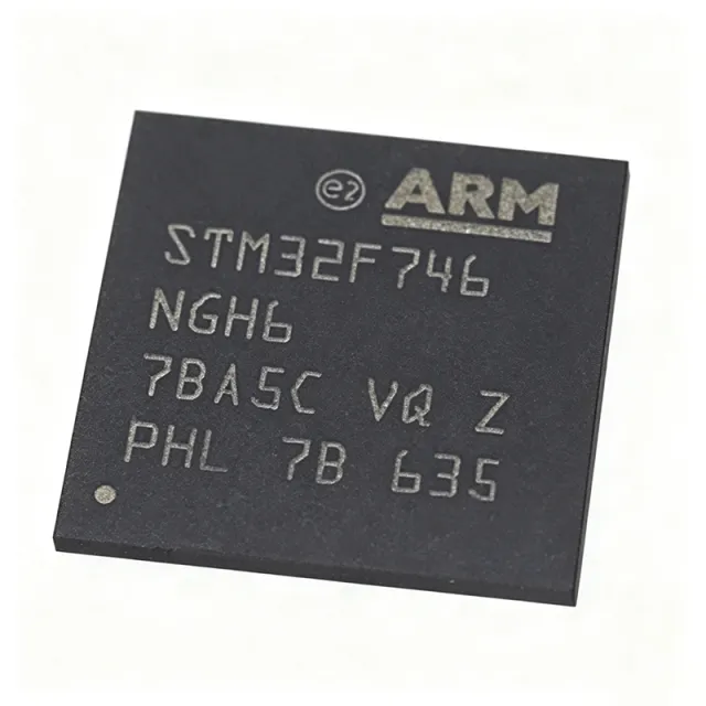
STM32F746NGH6 - 32-bit ARM Cortex-M7 MCU, 1MB Flash | STMicroelectronics
Référence : STM32F746NGH6 ✓ Actif| Qté | Prix unitaire | Total |
|---|---|---|
| 1 | $31.3636 | $31,36 |
| 10 | $22.6515 | $226,52 |
| 100 | $20.0379 | $2 003,79 |
| 500 | $19.1667 | $9 583,35 |
| 1 000 | $18.2955 | $18 295,50 |
STM32F746NGH6 Présentation
What is a microcontroller? A microcontroller (MCU) is a compact integrated circuit designed to govern a specific operation in an embedded system. It contains a processor core, memory (Flash and SRAM), and programmable input/output peripherals on a single chip. Microcontrollers are the backbone of modern electronics, found in automotive systems, industrial controls, consumer electronics, and IoT devices. The STM32F746NGH6 belongs to the STM32F7 series, which is part of the broader STM32 family of 32-bit ARM Cortex-M based MCUs, positioned as a high-performance option within the STM32 portfolio.
Key features of the STM32F746NGH6 include a 216 MHz ARM Cortex-M7 core with double-precision FPU and DSP instructions, 1 MB of Flash memory, 320 KB of SRAM, and a Chrom-ART Accelerator for advanced graphics. It supports a wide range of communication interfaces: 4x USART, 4x UART, 6x SPI, 4x I2C, 2x CAN, 1x SDMMC, 1x USB 2.0 OTG HS/FS, 1x Ethernet MAC, and 1x camera interface. The device also features a TFT-LCD controller supporting up to XGA resolution, a JPEG codec, and a true random number generator (TRNG).
Technically, the STM32F746NGH6 is built on a 40nm process technology, enabling high clock speeds with low power consumption. It includes a memory protection unit (MPU), a cache (I-Cache and D-Cache) to optimize performance, and a power management unit with multiple low-power modes. The device supports a supply voltage range of 1.7V to 3.6V and operates over a temperature range of -40°C to +85°C (H6 suffix indicates industrial temperature grade).
Typical applications include high-end consumer electronics, industrial automation, motor control, medical devices, and IoT gateways. The combination of high processing power, rich connectivity, and advanced graphics capabilities makes it ideal for human-machine interfaces (HMI), audio processing, and real-time control systems.
When designing with this MCU, ensure proper decoupling of the power supply pins and follow the layout guidelines in the datasheet for the TFBGA package. The device requires a 25 MHz crystal for the HSE oscillator and supports an internal 16 MHz HSI oscillator for cost-sensitive designs.
Alternatives de remplacement direct pour STM32F746NGH6 — même boîtier, compatible broche à broche. Les références à boîtier différent nécessitant une retouche du PCB sont exclues.
Variantes de cette série
Modèles de la même série directement compatibles avec STM32F746NGH6 (même facteur de forme et même empreinte) — différant par Communication Interfaces, Core, DMA, Flash Memory, Operating Temperature.
Outil de comparaison rapide — sélectionnez des références alternatives pour une comparaison côte à côte :
STM32F746NGH6TR
📋 Alternative de référence (hors catalogue)
STM32F746NGH6 Valeurs maximales et caractéristiques électriques
| Core | ARM Cortex-M7 |
| Max Clock Speed | 216 MHz |
| Flash Memory | 1 MB |
| SRAM | 320 KB |
| Tension d'alimentation | 1.7 V to 3.6 V |
| Température de fonctionnement | -40C to +85C |
| Boîtier | TFBGA-216 (13x13 mm) |
| GPIO Pins | 168 |
| ADC | 3x 12-bit, 2.4 MSPS |
| DAC | 2x 12-bit |
| Timers | 12x 16-bit, 2x 32-bit |
| Communication Interfaces | 4x USART, 4x UART, 6x SPI, 4x I2C, 2x CAN, 1x SDMMC, 1x USB OTG HS/FS, 1x Ethernet MAC |
| TFT-LCD Controller | Yes (up to XGA) |
| JPEG Codec | Yes |
| DMA | 2x DMA controllers with 16 streams each |
| RTC | Yes |
| Statut RoHS | Compliant |
Configuration des broches de STM32F746NGH6
| Broche A1 | VDD — Digital power supply |
| Broche A2 | VSS — Digital ground |
| Broche A3 | PA0 — GPIO/ADC |
| Broche A4 | PA1 — GPIO/ADC |
| Broche A5 | PA2 — GPIO/USART2_TX |
| Broche A6 | PA3 — GPIO/USART2_RX |
| Broche A7 | PA4 — GPIO/SPI1_NSS |
| Broche A8 | PA5 — GPIO/SPI1_SCK |
| Broche A9 | PA6 — GPIO/SPI1_MISO |
| Broche A10 | PA7 — GPIO/SPI1_MOSI |
| Broche A11 | PA8 — GPIO/USART1_CK |
| Broche A12 | PA9 — GPIO/USART1_TX |
| Broche A13 | PA10 — GPIO/USART1_RX |
| Broche A14 | PA11 — GPIO/USB_DM |
| Broche A15 | PA12 — GPIO/USB_DP |
| Broche A16 | PA13 — GPIO/SWDIO |
| Broche A17 | PA14 — GPIO/SWCLK |
| Broche A18 | PA15 — GPIO/JTDI |
| Broche B1 | PB0 — GPIO/ADC |
| Broche B2 | PB1 — GPIO/ADC |
| Broche B3 | PB2 — GPIO/BOOT1 |
| Broche B4 | PB3 — GPIO/JTDO |
| Broche B5 | PB4 — GPIO/NJTRST |
| Broche B6 | PB5 — GPIO/I2C1_SMBA |
| Broche B7 | PB6 — GPIO/I2C1_SCL |
| Broche B8 | PB7 — GPIO/I2C1_SDA |
| Broche B9 | PB8 — GPIO/I2C1_SCL |
| Broche B10 | PB9 — GPIO/I2C1_SDA |
| Broche B11 | PB10 — GPIO/I2C2_SCL |
| Broche B12 | PB11 — GPIO/I2C2_SDA |
| Broche B13 | PB12 — GPIO/SPI2_NSS |
| Broche B14 | PB13 — GPIO/SPI2_SCK |
| Broche B15 | PB14 — GPIO/SPI2_MISO |
| Broche B16 | PB15 — GPIO/SPI2_MOSI |
| Broche B17 | PB16 — GPIO/SPI1_NSS |
| Broche B18 | PB17 — GPIO/SPI1_SCK |
| Broche C1 | PC0 — GPIO/ADC |
| Broche C2 | PC1 — GPIO/ADC |
| Broche C3 | PC2 — GPIO/ADC |
| Broche C4 | PC3 — GPIO/ADC |
| Broche C5 | PC4 — GPIO/ADC |
| Broche C6 | PC5 — GPIO/ADC |
| Broche C7 | PC6 — GPIO/SDMMC1_CK |
| Broche C8 | PC7 — GPIO/SDMMC1_CMD |
| Broche C9 | PC8 — GPIO/SDMMC1_D0 |
| Broche C10 | PC9 — GPIO/SDMMC1_D1 |
| Broche C11 | PC10 — GPIO/SDMMC1_D2 |
| Broche C12 | PC11 — GPIO/SDMMC1_D3 |
| Broche C13 | PC12 — GPIO/SDMMC1_CK |
| Broche C14 | PC13 — GPIO/RTC_AF1 |
| Broche C15 | PC14 — GPIO/OSC32_IN |
| Broche C16 | PC15 — GPIO/OSC32_OUT |
| Broche C17 | PD0 — GPIO/FSMC_D2 |
| Broche C18 | PD1 — GPIO/FSMC_D3 |
| Broche D1 | PD2 — GPIO/SDMMC1_CK |
| Broche D2 | PD3 — GPIO/FSMC_CLK |
| Broche D3 | PD4 — GPIO/FSMC_NOE |
| Broche D4 | PD5 — GPIO/FSMC_NWE |
| Broche D5 | PD6 — GPIO/FSMC_NWAIT |
| Broche D6 | PD7 — GPIO/FSMC_NE1 |
| Broche D7 | PD8 — GPIO/FSMC_D13 |
| Broche D8 | PD9 — GPIO/FSMC_D14 |
| Broche D9 | PD10 — GPIO/FSMC_D15 |
| Broche D10 | PD11 — GPIO/FSMC_A16 |
| Broche D11 | PD12 — GPIO/FSMC_A17 |
| Broche D12 | PD13 — GPIO/FSMC_A18 |
| Broche D13 | PD14 — GPIO/FSMC_D0 |
| Broche D14 | PD15 — GPIO/FSMC_D1 |
| Broche D15 | PE0 — GPIO/FSMC_NBL0 |
| Broche D16 | PE1 — GPIO/FSMC_NBL1 |
| Broche D17 | PE2 — GPIO/FSMC_A23 |
| Broche D18 | PE3 — GPIO/FSMC_A19 |
| Broche E1 | PE4 — GPIO/FSMC_A20 |
| Broche E2 | PE5 — GPIO/FSMC_A21 |
| Broche E3 | PE6 — GPIO/FSMC_A22 |
| Broche E4 | PE7 — GPIO/FSMC_D4 |
| Broche E5 | PE8 — GPIO/FSMC_D5 |
| Broche E6 | PE9 — GPIO/FSMC_D6 |
| Broche E7 | PE10 — GPIO/FSMC_D7 |
| Broche E8 | PE11 — GPIO/FSMC_D8 |
| Broche E9 | PE12 — GPIO/FSMC_D9 |
| Broche E10 | PE13 — GPIO/FSMC_D10 |
| Broche E11 | PE14 — GPIO/FSMC_D11 |
| Broche E12 | PE15 — GPIO/FSMC_D12 |
| Broche E13 | PF0 — GPIO/FSMC_A0 |
| Broche E14 | PF1 — GPIO/FSMC_A1 |
| Broche E15 | PF2 — GPIO/FSMC_A2 |
| Broche E16 | PF3 — GPIO/FSMC_A3 |
| Broche E17 | PF4 — GPIO/FSMC_A4 |
| Broche E18 | PF5 — GPIO/FSMC_A5 |
| Broche F1 | PF6 — GPIO/FSMC_A6 |
| Broche F2 | PF7 — GPIO/FSMC_A7 |
| Broche F3 | PF8 — GPIO/FSMC_A8 |
| Broche F4 | PF9 — GPIO/FSMC_A9 |
| Broche F5 | PF10 — GPIO/FSMC_A10 |
| Broche F6 | PF11 — GPIO/FSMC_A11 |
| Broche F7 | PF12 — GPIO/FSMC_A12 |
| Broche F8 | PF13 — GPIO/FSMC_A13 |
| Broche F9 | PF14 — GPIO/FSMC_A14 |
| Broche F10 | PF15 — GPIO/FSMC_A15 |
| Broche F11 | PG0 — GPIO/FSMC_A16 |
| Broche F12 | PG1 — GPIO/FSMC_A17 |
| Broche F13 | PG2 — GPIO/FSMC_A18 |
| Broche F14 | PG3 — GPIO/FSMC_A19 |
| Broche F15 | PG4 — GPIO/FSMC_A20 |
| Broche F16 | PG5 — GPIO/FSMC_A21 |
| Broche F17 | PG6 — GPIO/FSMC_A22 |
| Broche F18 | PG7 — GPIO/FSMC_A23 |
| Broche G1 | PG8 — GPIO/FSMC_A24 |
| Broche G2 | PG9 — GPIO/FSMC_A25 |
| Broche G3 | PG10 — GPIO/FSMC_NE2 |
| Broche G4 | PG11 — GPIO/FSMC_NE3 |
| Broche G5 | PG12 — GPIO/FSMC_NE4 |
| Broche G6 | PG13 — GPIO/FSMC_A24 |
| Broche G7 | PG14 — GPIO/FSMC_A25 |
| Broche G8 | PG15 — GPIO/FSMC_A26 |
| Broche G9 | PH0 — GPIO/OSC_IN |
| Broche G10 | PH1 — GPIO/OSC_OUT |
| Broche G11 | PH2 — GPIO/FSMC_A27 |
| Broche G12 | PH3 — GPIO/FSMC_A28 |
| Broche G13 | PH4 — GPIO/FSMC_A29 |
| Broche G14 | PH5 — GPIO/FSMC_A30 |
| Broche G15 | PH6 — GPIO/FSMC_A31 |
| Broche G16 | PH7 — GPIO/FSMC_A32 |
| Broche G17 | PH8 — GPIO/FSMC_A33 |
| Broche G18 | PH9 — GPIO/FSMC_A34 |
| Broche H1 | PH10 — GPIO/FSMC_A35 |
| Broche H2 | PH11 — GPIO/FSMC_A36 |
| Broche H3 | PH12 — GPIO/FSMC_A37 |
| Broche H4 | PH13 — GPIO/FSMC_A38 |
| Broche H5 | PH14 — GPIO/FSMC_A39 |
| Broche H6 | PH15 — GPIO/FSMC_A40 |
| Broche H7 | PI0 — GPIO/FSMC_A41 |
| Broche H8 | PI1 — GPIO/FSMC_A42 |
| Broche H9 | PI2 — GPIO/FSMC_A43 |
| Broche H10 | PI3 — GPIO/FSMC_A44 |
| Broche H11 | PI4 — GPIO/FSMC_A45 |
| Broche H12 | PI5 — GPIO/FSMC_A46 |
| Broche H13 | PI6 — GPIO/FSMC_A47 |
| Broche H14 | PI7 — GPIO/FSMC_A48 |
| Broche H15 | PI8 — GPIO/FSMC_A49 |
| Broche H16 | PI9 — GPIO/FSMC_A50 |
| Broche H17 | PI10 — GPIO/FSMC_A51 |
| Broche H18 | PI11 — GPIO/FSMC_A52 |
| Broche J1 | VDD — Digital power supply |
| Broche J2 | VSS — Digital ground |
| Broche J3 | VCAP1 — Internal regulator capacitor |
| Broche J4 | VCAP2 — Internal regulator capacitor |
| Broche J5 | VREF+ — ADC reference voltage |
| Broche J6 | VREF- — ADC reference ground |
| Broche J7 | VDDA — Analog power supply |
| Broche J8 | VSSA — Analog ground |
| Broche J9 | VBAT — Battery backup supply |
| Broche J10 | NRST — Reset (active low) |
| Broche J11 | BOOT0 — Boot mode selection |
| Broche J12 | VDD — Digital power supply |
| Broche J13 | VSS — Digital ground |
| Broche J14 | VDD — Digital power supply |
| Broche J15 | VSS — Digital ground |
| Broche J16 | VDD — Digital power supply |
| Broche J17 | VSS — Digital ground |
| Broche J18 | VDD — Digital power supply |
Applications typiques
STM32F746NGH6 convient pour 6 applications: Human-Machine Interface (HMI), Industrial Automation, IoT Gateway, Medical Devices, Audio Processing, Consumer Electronics.
Human-Machine Interface (HMI)
The STM32F746NGH6 is ideal for HMI applications due to its integrated TFT-LCD controller supporting up to XGA resolution, Chrom-ART Accelerator for 2D graphics, and JPEG codec. It can drive high-resolution displays directly, enabling rich graphical user interfaces in industrial panels, medical devices, and consumer electronics. The 216 MHz Cortex-M7 core ensures smooth rendering and responsive touch input. With 1 MB Flash and 320 KB SRAM, complex GUI frameworks like TouchGFX and STemWin can be implemented without external memory. The device's low power modes and wide supply voltage range (1.7V-3.6V) make it suitable for battery-powered handheld HMIs. Designers can leverage the STM32CubeMX tool for rapid prototyping and the STM32CubeF7 firmware package for optimized drivers.
Recommandé
Industrial Automation
The STM32F746NGH6 excels in industrial automation due to its robust communication interfaces including 2x CAN, Ethernet MAC, and multiple UART/SPI/I2C. It can serve as a central controller in PLCs, motor drives, and robotic systems. The 216 MHz Cortex-M7 core with DSP instructions handles complex control algorithms like field-oriented control (FOC) for motors. The device's 12-bit ADCs with 2.4 MSPS sampling rate enable precise sensor acquisition. Its industrial temperature grade (-40°C to +85°C) ensures reliable operation in harsh environments. The TFBGA-216 package provides 168 GPIOs for interfacing with sensors, actuators, and communication modules. STM32CubeMX and STM32CubeF7 provide HAL drivers and middleware for CANopen, EtherCAT, and other industrial protocols.
Recommandé
IoT Gateway
The STM32F746NGH6 is well-suited for IoT gateways due to its Ethernet MAC, USB OTG, and multiple communication interfaces. It can aggregate data from various sensors and devices, process it locally, and transmit to the cloud via Ethernet or Wi-Fi (using external modules). The 216 MHz Cortex-M7 core provides ample processing power for protocol stacks like MQTT, CoAP, and TLS. The device's 1 MB Flash and 320 KB SRAM support running a full TCP/IP stack (e.g., lwIP) and application code. Its low power modes enable energy-efficient operation, critical for always-on gateways. The TFBGA-216 package's compact size allows integration into small form-factor gateways. STM32CubeF7 includes middleware for IoT connectivity, including Azure RTOS and AWS IoT integration.
Recommandé
Medical Devices
The STM32F746NGH6 is used in medical devices such as patient monitors, infusion pumps, and diagnostic equipment. Its high processing power enables real-time signal processing for ECG, EEG, and other biosignals. The integrated TFT-LCD controller supports high-resolution displays for patient data visualization. The device's multiple ADCs and DACs interface with analog front-ends for sensor conditioning. Its industrial temperature grade and wide supply voltage range ensure reliable operation in medical environments. The 1 MB Flash allows storing patient data and firmware updates. STM32CubeF7 provides safety-related documentation and support for IEC 62304 compliance. The TFBGA-216 package's small footprint is advantageous for portable medical devices.
Recommandé
Audio Processing
The STM32F746NGH6 is ideal for audio processing applications such as audio interfaces, voice recognition, and active noise cancellation. The 216 MHz Cortex-M7 core with DSP instructions and double-precision FPU handles complex audio algorithms like FIR/IIR filters, FFT, and codecs. The device includes a dedicated audio PLL and multiple I2S interfaces for high-quality audio streaming. Its 2x 12-bit DACs can output analog audio directly. The 1 MB Flash and 320 KB SRAM support storing audio samples and processing buffers. The TFBGA-216 package's compact size is suitable for portable audio devices. STM32CubeF7 provides audio middleware including USB Audio Class and SAI drivers.
Recommandé
Consumer Electronics
The STM32F746NGH6 is used in high-end consumer electronics like smart home hubs, wearable devices, and gaming peripherals. Its high performance and rich peripherals enable feature-rich products. The TFT-LCD controller and Chrom-ART Accelerator support vibrant displays for smart watches and control panels. The device's USB OTG and Ethernet interfaces enable connectivity with smartphones and home networks. Its low power modes extend battery life in portable devices. The 1 MB Flash and 320 KB SRAM allow running complex applications and user interfaces. The TFBGA-216 package's small size is ideal for compact consumer products. STM32CubeF7 provides middleware for USB, graphics, and file systems.
Recommandé
Récapitulatif des produits recommandés
Données de référence d'ingénierie pour STM32F746NGH6 — comparaison, recommandations de conception et informations de conformité.
Guide de sélection
Comparaison avec les alternatives
| Paramètre | Ce produit | STM32F746NGH6TR | STM32F746NGH6 | STM32F746NGH6 |
|---|---|---|---|---|
| Package | TFBGA-216 (13x13 mm) | TFBGA-216 (13x13 mm) - same | TFBGA-216 (13x13 mm) - same | TFBGA-216 (13x13 mm) - same |
| Brand | STMicroelectronics | STMicroelectronics | STMicroelectronics | STMicroelectronics |
| Core | ARM Cortex-M7 | ARM Cortex-M7 | ARM Cortex-M7 | ARM Cortex-M7 |
| Max Clock Speed | 216 MHz | 216 MHz | 216 MHz | 216 MHz |
| Flash Memory | 1 MB | 1 MB | 1 MB | 1 MB |
| SRAM | 320 KB | 320 KB | 320 KB | 320 KB |
| GPIO Pins | 168 | 168 | 168 | 168 |
| TFT-LCD Controller | Yes | Yes | Yes | Yes |
Principaux différenciateurs
- Higher GPIO count in TFBGA package (vs STM32F746ZGT6 (LQFP-144))
- Integrated TFT-LCD controller and Chrom-ART Accelerator (vs STM32F407ZGT6)
- Higher clock speed and performance (vs STM32F429ZIT6)
Notes de conception
The STM32F746NGH6 requires a stable power supply. Decouple each VDD pin with a 100nF ceramic capacitor placed as close as possible to the pin. Additionally, use a 4.7uF capacitor on the VCAP1 and VCAP2 pins for the internal voltage regulator. Ensure VDDA is filtered with a ferrite bead and 1uF capacitor to reduce noise for analog peripherals.
For the TFBGA-216 package, use a 4-layer PCB with a solid ground plane. Route high-speed signals (Ethernet, USB, SDMMC) with controlled impedance (e.g., 50 ohms for Ethernet). Keep crystal oscillator traces short and away from high-current traces. Follow the layout guidelines in the STM32F746NG datasheet (Section 7) for optimal performance.
Ensure the BOOT0 pin is properly configured to select the desired boot mode. For debugging, connect SWDIO and SWCLK pins with pull-up/pull-down resistors as recommended. Do not leave unused GPIO pins floating; configure them as outputs or enable internal pull-ups. Also, verify that the HSE crystal load capacitors match the crystal's specified load capacitance.
Informations de conformité
RoHS compliant per STMicroelectronics product page. Not AEC-Q100 qualified - this is an industrial-grade MCU.







