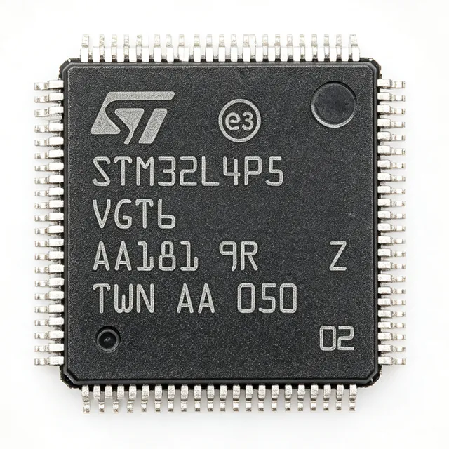
STM32L4P5VGT6 - Ultra-Low-Power Cortex-M4 MCU | STMicroelectronics
Référence : STM32L4P5VGT6 ✓ Actif| Qté | Prix unitaire | Total |
|---|---|---|
| 1 | $19.0909 | $19,09 |
| 10 | $13.7879 | $137,88 |
| 100 | $12.197 | $1 219,70 |
| 500 | $11.6667 | $5 833,35 |
| 1 000 | $11.1364 | $11 136,40 |
STM32L4P5VGT6 Présentation
What is an ARM Cortex-M4 microcontroller? It is a 32-bit processor core designed for embedded systems, featuring a single-cycle multiply-accumulate (MAC) unit, hardware divide, and optional single-precision floating-point unit (FPU). The Cortex-M4 is part of the ARM Cortex-M family, which includes the M0, M0+, M3, M4, and M7 cores, each optimized for different performance and power trade-offs. In the system hierarchy, a microcontroller (MCU) integrates the processor core, memory, and peripherals on a single chip, serving as the central processing unit in embedded systems such as IoT devices, industrial controllers, and consumer electronics.
Key features include a rich set of analog peripherals: two 12-bit DACs, three 12-bit ADCs with hardware oversampling, two operational amplifiers, two comparators, and an internal voltage reference buffer. The device also integrates advanced digital peripherals: two CAN FD controllers, one USB 2.0 OTG FS/HS, one SDMMC interface, and a flexible memory controller (FMC) for external memory expansion. The STM32L4P5VGT6 supports multiple low-power modes, including Sleep, Low-power Run, Low-power Sleep, Stop 0/1/2, and Standby, with a typical current consumption of 100 nA in Standby mode with backup domain.
The STM32L4P5VGT6 is built on ST's ultra-low-power technology, featuring a dynamic voltage scaling (DVS) capability that adjusts the core voltage to optimize power consumption at different operating frequencies. The device includes a hardware cryptographic accelerator (AES, DES, 3DES) and a true random number generator (TRNG), enhancing security for connected applications. The rich set of timers includes two advanced-control timers, six general-purpose timers, two basic timers, and two low-power timers, providing precise timing and PWM generation.
Typical applications include IoT nodes, smart meters, portable medical devices, industrial sensors, and wearable devices. The ultra-low-power modes and high integration make it ideal for battery-powered systems requiring long operational life. The device also supports a wide operating temperature range of -40°C to +85°C, suitable for industrial environments.
When designing with this MCU, pay attention to the power supply decoupling: place a 100 nF capacitor close to each VDD pin and a 4.7 uF capacitor at the main power input. For low-power operation, configure the GPIOs to analog mode when unused to reduce leakage current. The STM32L4P5VGT6 is supported by STM32CubeMX and STM32CubeL4 firmware package, simplifying development.
Alternatives de remplacement direct pour STM32L4P5VGT6 — même boîtier, compatible broche à broche. Les références à boîtier différent nécessitant une retouche du PCB sont exclues.
Outil de comparaison rapide — sélectionnez des références alternatives pour une comparaison côte à côte :
STM32L4A6RGT6
✓ En stock
$9.56 / unité
Voir la fiche technique →STM32L4P5VGT6P
📋 Alternative de référence (hors catalogue)
STM32L4R5VGT6
📋 Alternative de référence (hors catalogue)
GD32F450VGT6
📋 Alternative de référence (hors catalogue)
LPC4357FET256
✓ En stock
$9.5 / unité
Voir la fiche technique →STM32L4P5VGT6 Valeurs maximales et caractéristiques électriques
| Core | ARM Cortex-M4 with FPU |
| Fréquence d'horloge maximale | 120 MHz |
| Flash Memory | 1 MB |
| SRAM | 320 KB |
| Boîtier | 100-LQFP (14x14 mm) |
| Plage de température de fonctionnement | -40°C to +85°C |
| Supply Voltage Range | 1.71 V to 3.6 V |
| DMIPS | 213 |
| CoreMark | 550 |
| DAC | 2x 12-bit |
| ADC | 3x 12-bit with hardware oversampling |
| Operational Amplifiers | 2 |
| Comparators | 2 |
| CAN FD | 2 |
| USB | USB 2.0 OTG FS/HS |
| SDMMC | 1 |
| FMC | Yes |
| Low-Power Modes | Sleep, Low-power Run, Low-power Sleep, Stop 0/1/2, Standby |
| Standby Current | 100 nA (typical, with backup domain) |
| Cryptographic Accelerator | AES, DES, 3DES |
| TRNG | Yes |
| Timers | 2 advanced-control, 6 general-purpose, 2 basic, 2 low-power |
| RoHS | Compliant |
Configuration des broches de STM32L4P5VGT6
| Broche 1 | VBAT — Backup battery supply |
| Broche 2 | PC13 — GPIO / RTC output |
| Broche 3 | PC14 — GPIO / OSC32_IN |
| Broche 4 | PC15 — GPIO / OSC32_OUT |
| Broche 5 | PF0 — GPIO / OSC_IN |
| Broche 6 | PF1 — GPIO / OSC_OUT |
| Broche 7 | NRST — Reset (active low) |
| Broche 8 | VSSA — Analog ground |
| Broche 9 | VDDA — Analog power supply |
| Broche 10 | PA0 — GPIO / ADC / DAC / TIM2_CH1 |
| Broche 11 | PA1 — GPIO / ADC / DAC / TIM2_CH2 |
| Broche 12 | PA2 — GPIO / ADC / USART2_TX / TIM2_CH3 |
| Broche 13 | PA3 — GPIO / ADC / USART2_RX / TIM2_CH4 |
| Broche 14 | VSS — Ground |
| Broche 15 | VDD — Power supply |
| Broche 16 | PA4 — GPIO / ADC / DAC / SPI1_NSS |
| Broche 17 | PA5 — GPIO / ADC / DAC / SPI1_SCK |
| Broche 18 | PA6 — GPIO / ADC / SPI1_MISO / TIM3_CH1 |
| Broche 19 | PA7 — GPIO / ADC / SPI1_MOSI / TIM3_CH2 |
| Broche 20 | PC4 — GPIO / ADC / I2S1_WS |
| Broche 21 | PC5 — GPIO / ADC / I2S1_CK |
| Broche 22 | PB0 — GPIO / ADC / TIM3_CH3 |
| Broche 23 | PB1 — GPIO / ADC / TIM3_CH4 |
| Broche 24 | PB2 — GPIO / RTC / TIM1_CH3N |
| Broche 25 | PB10 — GPIO / I2C2_SCL / USART3_TX |
| Broche 26 | PB11 — GPIO / I2C2_SDA / USART3_RX |
| Broche 27 | VSS — Ground |
| Broche 28 | VDD — Power supply |
| Broche 29 | PB12 — GPIO / SPI2_NSS / TIM1_BKIN |
| Broche 30 | PB13 — GPIO / SPI2_SCK / TIM1_CH1N |
| Broche 31 | PB14 — GPIO / SPI2_MISO / TIM1_CH2N |
| Broche 32 | PB15 — GPIO / SPI2_MOSI / TIM1_CH3N |
| Broche 33 | PC6 — GPIO / I2S2_MCK / TIM3_CH1 |
| Broche 34 | PC7 — GPIO / I2S2_MCK / TIM3_CH2 |
| Broche 35 | PC8 — GPIO / TIM3_CH3 / SDMMC1_CK |
| Broche 36 | PC9 — GPIO / TIM3_CH4 / SDMMC1_CK |
| Broche 37 | PA8 — GPIO / MCO / TIM1_CH1 |
| Broche 38 | PA9 — GPIO / USART1_TX / TIM1_CH2 |
| Broche 39 | PA10 — GPIO / USART1_RX / TIM1_CH3 |
| Broche 40 | PA11 — GPIO / USB_DM / CAN1_RX |
| Broche 41 | PA12 — GPIO / USB_DP / CAN1_TX |
| Broche 42 | PA13 — GPIO / SWDIO |
| Broche 43 | VSS — Ground |
| Broche 44 | VDD — Power supply |
| Broche 45 | PA14 — GPIO / SWCLK |
| Broche 46 | PA15 — GPIO / JTDI / TIM2_CH1 |
| Broche 47 | PC10 — GPIO / USART3_TX / SDMMC1_D2 |
| Broche 48 | PC11 — GPIO / USART3_RX / SDMMC1_D3 |
| Broche 49 | PC12 — GPIO / USART3_CK / SDMMC1_CK |
| Broche 50 | PD2 — GPIO / TIM3_ETR / SDMMC1_CMD |
| Broche 51 | PB3 — GPIO / JTDO / SPI1_SCK |
| Broche 52 | PB4 — GPIO / JTRST / SPI1_MISO |
| Broche 53 | PB5 — GPIO / I2C1_SMBA / SPI1_MOSI |
| Broche 54 | PB6 — GPIO / I2C1_SCL / USART1_TX |
| Broche 55 | PB7 — GPIO / I2C1_SDA / USART1_RX |
| Broche 56 | BOOT0 — Boot mode selection |
| Broche 57 | PB8 — GPIO / I2C1_SCL / CAN1_RX |
| Broche 58 | PB9 — GPIO / I2C1_SDA / CAN1_TX |
| Broche 59 | VSS — Ground |
| Broche 60 | VDD — Power supply |
| Broche 61 | PE0 — GPIO / TIM4_ETR |
| Broche 62 | PE1 — GPIO / TIM4_CH1 |
| Broche 63 | PE2 — GPIO / TIM4_CH2 |
| Broche 64 | PE3 — GPIO / TIM4_CH3 |
| Broche 65 | PE4 — GPIO / TIM4_CH4 |
| Broche 66 | PE5 — GPIO / TIM9_CH1 |
| Broche 67 | PE6 — GPIO / TIM9_CH2 |
| Broche 68 | PE7 — GPIO / TIM1_ETR |
| Broche 69 | PE8 — GPIO / TIM1_CH1N |
| Broche 70 | PE9 — GPIO / TIM1_CH1 |
| Broche 71 | PE10 — GPIO / TIM1_CH2N |
| Broche 72 | PE11 — GPIO / TIM1_CH2 |
| Broche 73 | PE12 — GPIO / TIM1_CH3N |
| Broche 74 | PE13 — GPIO / TIM1_CH3 |
| Broche 75 | PE14 — GPIO / TIM1_BKIN |
| Broche 76 | PE15 — GPIO / TIM1_BKIN2 |
| Broche 77 | PB10 — GPIO / I2C2_SCL / USART3_TX |
| Broche 78 | PB11 — GPIO / I2C2_SDA / USART3_RX |
| Broche 79 | VSS — Ground |
| Broche 80 | VDD — Power supply |
| Broche 81 | PD8 — GPIO / USART3_TX / FMC_D13 |
| Broche 82 | PD9 — GPIO / USART3_RX / FMC_D14 |
| Broche 83 | PD10 — GPIO / USART3_CK / FMC_D15 |
| Broche 84 | PD11 — GPIO / FMC_A16 |
| Broche 85 | PD12 — GPIO / FMC_A17 |
| Broche 86 | PD13 — GPIO / FMC_A18 |
| Broche 87 | PD14 — GPIO / FMC_D0 |
| Broche 88 | PD15 — GPIO / FMC_D1 |
| Broche 89 | PD0 — GPIO / FMC_D2 |
| Broche 90 | PD1 — GPIO / FMC_D3 |
| Broche 91 | PD3 — GPIO / FMC_CLK |
| Broche 92 | PD4 — GPIO / FMC_NOE |
| Broche 93 | PD5 — GPIO / FMC_NWE |
| Broche 94 | PD6 — GPIO / FMC_NWAIT |
| Broche 95 | PD7 — GPIO / FMC_NE1 |
| Broche 96 | VSS — Ground |
| Broche 97 | VDD — Power supply |
| Broche 98 | PH0 — GPIO / OSC_IN |
| Broche 99 | PH1 — GPIO / OSC_OUT |
| Broche 100 | VSS — Ground |
Applications typiques
STM32L4P5VGT6 convient pour 6 applications: IoT Nodes, Smart Meters, Portable Medical Devices, Industrial Sensors, Wearable Devices, Smart Home Controllers.
IoT Nodes
The STM32L4P5VGT6 is ideal for IoT nodes due to its ultra-low-power modes (100 nA standby) and rich connectivity options including USB OTG, CAN FD, and SDMMC. Its 120 MHz Cortex-M4 core with FPU handles complex protocols like MQTT and TLS efficiently. The hardware cryptographic accelerator (AES, DES, 3DES) and TRNG secure data transmission. With 1 MB flash and 320 KB SRAM, it can store firmware and sensor data locally. The wide operating temperature range (-40°C to +85°C) suits outdoor deployments. Designers can leverage STM32CubeMX for rapid development and power optimization.
Recommandé
Smart Meters
Smart meters require precise measurement and low power consumption. The STM32L4P5VGT6's three 12-bit ADCs with hardware oversampling enable accurate current and voltage sensing. Its multiple low-power modes allow the meter to sleep between readings, extending battery life. The CAN FD interface supports communication with other smart grid devices. The FMC can connect to external memory for data logging. The device's robust security features (AES, TRNG) protect metering data. With a wide temperature range, it operates reliably in outdoor utility enclosures. ST's ultra-low-power technology ensures minimal energy consumption during active and standby states.
Recommandé
Portable Medical Devices
Portable medical devices demand high reliability and low power. The STM32L4P5VGT6's ultra-low-power modes extend battery life in devices like glucose monitors and pulse oximeters. Its analog peripherals (op-amps, comparators, ADCs) interface directly with biosensors. The 120 MHz Cortex-M4 with FPU handles signal processing algorithms for vital sign monitoring. The device's security features protect patient data. The compact 100-LQFP package fits space-constrained designs. ST's comprehensive firmware libraries (STM32CubeL4) accelerate development and certification. The wide temperature range ensures operation in clinical and home environments.
Recommandé
Industrial Sensors
Industrial sensors require robust performance and connectivity. The STM32L4P5VGT6's CAN FD and USB interfaces enable integration with industrial networks. Its multiple timers generate precise PWM for actuator control. The device's wide temperature range (-40°C to +85°C) and high reliability make it suitable for factory automation. The 12-bit ADCs with oversampling provide accurate sensor readings. The FMC supports external memory for data logging. The cryptographic accelerator secures communication in critical infrastructure. ST's long-term availability and industrial-grade quality ensure dependable operation in harsh environments.
Recommandé
Wearable Devices
Wearables need ultra-low power and small size. The STM32L4P5VGT6's 100 nA standby current and multiple low-power modes enable long battery life in smartwatches and fitness trackers. Its 120 MHz Cortex-M4 with FPU handles sensor fusion and user interface tasks. The device's analog peripherals interface with accelerometers, gyroscopes, and heart-rate sensors. The compact 100-LQFP package is suitable for space-constrained PCBs. The security features protect user data. ST's ultra-low-power technology and comprehensive power management tools help designers achieve optimal energy efficiency. The device supports Bluetooth via external modules for connectivity.
Recommandé
Smart Home Controllers
Smart home controllers require connectivity and low power. The STM32L4P5VGT6's USB OTG and CAN FD interfaces support various smart home protocols. Its multiple timers and PWM outputs control lighting and motorized devices. The device's low-power modes allow it to run on batteries or energy harvesting. The 1 MB flash provides ample space for complex home automation firmware. The security features (AES, TRNG) secure communication with cloud services. The wide temperature range suits indoor and outdoor installations. ST's ecosystem includes ready-to-use examples for smart home applications, accelerating time-to-market.
Recommandé
Récapitulatif des produits recommandés
Données de référence d'ingénierie pour STM32L4P5VGT6 — comparaison, recommandations de conception et informations de conformité.
Guide de sélection
Comparaison avec les alternatives
| Paramètre | Ce produit | STM32L4P5VGT6P | STM32L4R5VGT6 | STM32L4A6RGT6 | GD32F450VGT6 | LPC4357FET256 |
|---|---|---|---|---|---|---|
| Package | 100-LQFP (14x14 mm) | 100-LQFP (14x14 mm) - same | 100-LQFP (14x14 mm) - same | 100-LQFP (14x14 mm) - same | 100-LQFP (14x14 mm) - same | 100-LQFP (14x14 mm) - same |
| Brand | STMicroelectronics | STMicroelectronics | STMicroelectronics | STMicroelectronics | GigaDevice | NXP Semiconductors |
| Core | ARM Cortex-M4 with FPU | ARM Cortex-M4 with FPU | ARM Cortex-M4 with FPU | ARM Cortex-M4 with FPU | ARM Cortex-M4 with FPU | ARM Cortex-M4/M0 dual-core |
| Maximum Clock Frequency | 120 MHz | 120 MHz | 120 MHz | 80 MHz | 200 MHz | 204 MHz |
| Flash Memory | 1 MB | 1 MB | 1 MB | 1 MB | 1 MB | 1 MB |
| SRAM | 320 KB | 320 KB | 640 KB | 128 KB | 256 KB | 136 KB |
| Cryptographic Accelerator | AES, DES, 3DES | AES, DES, 3DES | AES, DES, 3DES | AES, DES, 3DES | AES, DES, 3DES | AES |
Principaux différenciateurs
- Higher clock speed and SRAM (vs STM32L4A6RGT6)
- External SMPS support option (vs STM32L4P5VGT6P)
- Lower power consumption (vs GD32F450VGT6)
Notes de conception
For low-power operation, configure unused GPIOs to analog mode to reduce leakage current. Use the low-power modes (Stop 2, Standby) to minimize consumption. Ensure the backup domain is properly powered with VBAT for RTC and backup registers. According to ST application note AN4621, using the internal LDO or external SMPS (on 'P' variants) can optimize power efficiency.
Place a 100 nF decoupling capacitor close to each VDD pin and a 4.7 uF capacitor at the main power input. For the VDDA pin, use a dedicated analog supply with a ferrite bead to reduce noise. Ensure a solid ground plane for the LQFP package's exposed pad (if present) to improve thermal performance.
Do not exceed the absolute maximum ratings for supply voltage (3.6V). Ensure the boot pins (BOOT0) are configured correctly for your application. When using the 'P' variant, if VDD12 pins are not used, leave them unconnected to avoid short circuits. Verify the crystal oscillator layout for OSC_IN/OSC_OUT to prevent startup issues.
Informations de conformité
RoHS compliant per STMicroelectronics product page. Not AEC-Q100 qualified; this is a general-purpose MCU.