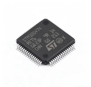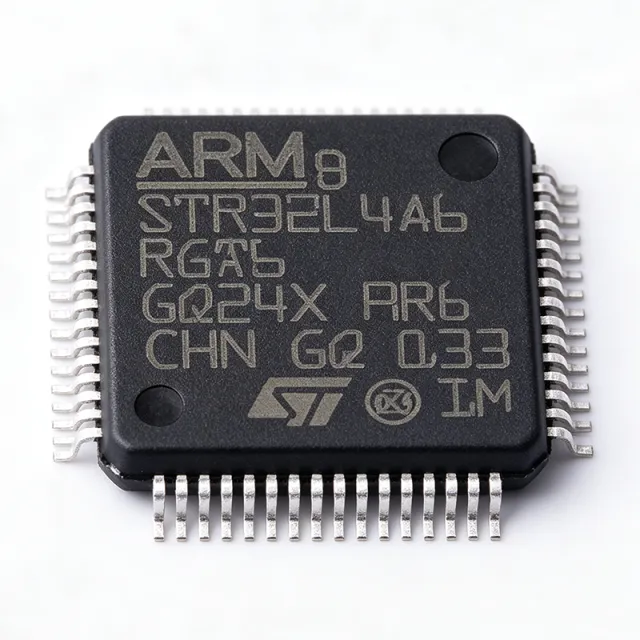
STM32L4A6RGT6 - Cortex-M4 80MHz 1MB Flash MCU | STMicroelectronics
MPN: STM32L4A6RGT6 ✓ Active| Qty | Unit Price | Extended |
|---|---|---|
| 1 | $14.73 | $14.73 |
| 10 | $13.25 | $132.50 |
| 100 | $11.8 | $1,180.00 |
| 500 | $10.62 | $5,310.00 |
| 1,000 | $9.56 | $9,560.00 |
STM32L4A6RGT6 Overview
An ultra-low-power microcontroller (MCU) is a system-on-chip that integrates a processor core, memory, and analog/digital peripherals on a single die, designed to minimize energy consumption in battery-powered and energy-harvesting systems. Within the power-management IC hierarchy, the STM32L4A6RGT6 belongs to the STM32L4 series of the STM32 family, which spans from low-power to high-performance ARM Cortex-M devices, and is positioned among the most energy-efficient Cortex-M MCUs on the market.
Key differentiating features include a rich analog subsystem - two 12-bit DACs, two operational amplifiers, two ultra-low-power comparators, and a 16-bit ADC with hardware oversampling - plus a shutdown mode drawing as little as 28 nA. Digital connectivity covers USB OTG full-speed, two CAN 2.0B controllers, SDMMC, LCD controller, and multiple USART, SPI, and I2C ports, all supported across a 1.71V to 3.6V supply range.
The device is manufactured on a 40 nm process and includes an AES cryptographic accelerator, a true random number generator (TRNG), a flexible memory protection unit (MPU), the Chrom-ART Accelerator (DMA2D) for graphics, and a 16-bit advanced motor-control timer. These blocks enable secure, GUI-enabled, and motor-driven products without external co-processors.
Typical applications include industrial sensors, smart meters, medical and wearable devices, and IoT endpoints, where the combination of 28 nA shutdown, 80 MHz processing, and 1 MB flash removes the need for external memory or power-management companion ICs.
Designers should carefully plan power-supply decoupling and PCB layout to realize the specified low-power figures, and should leverage the internal LDO or SMPS step-down options plus the graded low-power modes to maximize battery life.
This page adds information gain beyond the manufacturer datasheet: drop-in alternatives with package and parameter matching, distributor pricing as of 2026-09-06, practical design notes, and a selection guide comparing the STM32L4A6RGT6 against same-footprint parts.
Drop-in alternatives for STM32L4A6RGT6 — same package, pin-to-pin compatible. Different-package parts requiring PCB rework are excluded.
Variants in this series
Same-series models that are drop-in compatible with STM32L4A6RGT6 (same form factor and footprint) — differing in Package, Flash Memory, SRAM, Core, Performance.
Quick Comparison Tool — Select alternative parts for side-by-side comparison:
STM32L4A6RGT7TR
✅ Drop-In📋 Reference alternative (not in catalog)
STM32L496RGT6
✅ Drop-In✓ In Stock
$2.85 / Unit
View Datasheet →STM32L452RET6TR
✅ Drop-In📋 Reference alternative (not in catalog)
STM32L4A6RGT7
✅ Drop-In ⚠️ 参数待验证📋 Reference alternative (not in catalog)
STM32L486RGT6
✅ Drop-In ⚠️ 参数待验证✓ In Stock
$8.5 / Unit
View Datasheet →STM32L4A6RGT6 Maximum Ratings & Electrical Characteristics
| Core | ARM Cortex-M4 with FPU, 32-bit |
| Maximum Frequency | 80 MHz |
| Performance | 100 DMIPS (1.25 DMIPS/MHz) |
| Flash Memory | 1 MB |
| SRAM | 320 KB |
| Supply Voltage | 1.71 V to 3.6 V |
| Shutdown Mode Current | 28 nA |
| DAC Channels | 2 x 12-bit |
| ADC | 16-bit with hardware oversampling |
| Comparators | 2 x ultra-low-power |
| Operational Amplifiers | 2 |
| USB | USB OTG full-speed |
| CAN | 2 x CAN 2.0B |
| Security | AES accelerator, TRNG |
| Graphics | Chrom-ART Accelerator (DMA2D), LCD controller |
| Package | LQFP-64 (10x10 mm) |
| Mounting Type | Surface Mount |
| Operating Temperature | -40C to +85C |
| Process Technology | 40 nm |
| RoHS Status | Compliant |
STM32L4A6RGT6 Pin Configuration
| Pin 1 | PC13 — GPIO / anti-tamper / RTC AF |
| Pin 2 | PC14-OSC32_IN — GPIO / 32.768 kHz oscillator input |
| Pin 3 | PC15-OSC32_OUT — GPIO / 32.768 kHz oscillator output |
| Pin 4 | PH0-OSC_IN — GPIO / main oscillator input |
| Pin 5 | PH1-OSC_OUT — GPIO / main oscillator output |
| Pin 6 | NRST — System reset (active low) |
| Pin 7 | PC0 — GPIO / ADC / LPTIM |
| Pin 8 | PC1 — GPIO / ADC / LPTIM |
| Pin 9 | PC2 — GPIO / ADC / LPTIM |
| Pin 10 | PC3 — GPIO / ADC / OPAMP |
| Pin 11 | VSSA — Analog ground |
| Pin 12 | VREF- — ADC/DAC negative reference |
| Pin 13 | VREF+ — ADC/DAC positive reference |
| Pin 14 | VDDA — Analog power supply |
| Pin 15 | PA0 — GPIO / ADC / op-amp / WKUP |
| Pin 16 | PA1 — GPIO / ADC / op-amp / WKUP |
| Pin 17 | PA2 — GPIO / USART2_TX / ADC / op-amp |
| Pin 18 | PA3 — GPIO / USART2_RX / ADC / op-amp |
| Pin 19 | VSS — Ground |
| Pin 20 | VDD — Power supply |
| Pin 21 | PA4 — GPIO / DAC / SPI1_NSS / ADC |
| Pin 22 | PA5 — GPIO / DAC / SPI1_SCK / ADC |
| Pin 23 | PA6 — GPIO / SPI1_MISO / ADC |
| Pin 24 | PA7 — GPIO / SPI1_MOSI / ADC |
| Pin 25 | PC4 — GPIO / ADC / op-amp |
| Pin 26 | PC5 — GPIO / ADC / op-amp |
| Pin 27 | PB0 — GPIO / ADC / op-amp / WKUP |
| Pin 28 | PB1 — GPIO / ADC / op-amp / WKUP |
| Pin 29 | PB2 — GPIO / ADC / DFSDM |
| Pin 30 | PB10 — GPIO / I2C1_SCL / USART3_TX / DFSDM |
| Pin 31 | PB11 — GPIO / I2C1_SDA / USART3_RX |
| Pin 32 | VSS1 — Ground |
| Pin 33 | VDD1 — Power supply |
| Pin 34 | PB12 — GPIO / SPI2_NSS / CAN2 / DFSDM |
| Pin 35 | PB13 — GPIO / SPI2_SCK / CAN2 / DFSDM |
| Pin 36 | PB14 — GPIO / SPI2_MISO / USART3_TX / LCD |
| Pin 37 | PB15 — GPIO / SPI2_MOSI / USART3_RX / LCD |
| Pin 38 | PC6 — GPIO / USART6_TX / SDMMC / LCD |
| Pin 39 | PC7 — GPIO / USART6_RX / SDMMC / LCD |
| Pin 40 | PC8 — GPIO / SDMMC / LCD |
| Pin 41 | PC9 — GPIO / SDMMC / I2C3_SDA / LCD |
| Pin 42 | PA8 — GPIO / USART1_CK / USB_SOF / MCO1 |
| Pin 43 | PA9 — GPIO / USART1_TX / USB_VBUS / MCO2 |
| Pin 44 | PA10 — GPIO / USART1_RX / USB_ID / LCD |
| Pin 45 | PA11 — GPIO / USB_DM / CAN1_RX / LCD |
| Pin 46 | PA12 — GPIO / USB_DP / CAN1_TX / LCD |
| Pin 47 | PA13 — GPIO / SWDIO (debug) |
| Pin 48 | VSS2 — Ground |
| Pin 49 | VDD2 — Power supply |
| Pin 50 | PA14 — GPIO / SWCLK (debug) |
| Pin 51 | PA15 — GPIO / SPI1_NSS / USART2_RX |
| Pin 52 | PC10 — GPIO / SDMMC / USART3_TX / LCD |
| Pin 53 | PC11 — GPIO / SDMMC / USART3_RX / LCD |
| Pin 54 | PC12 — GPIO / SDMMC / USART3_CK / LCD |
| Pin 55 | PD2 — GPIO / SDMMC_CMD / USART3_RX / TIM |
| Pin 56 | PB3 — GPIO / SPI1_SCK / SWO (trace output) |
| Pin 57 | PB4 — GPIO / SPI1_MISO / CAN2_RX |
| Pin 58 | PB5 — GPIO / SPI1_MOSI / CAN2_TX / LCD |
| Pin 59 | PB6 — GPIO / I2C1_SCL / USART1_TX / LCD |
| Pin 60 | PB7 — GPIO / I2C1_SDA / USART1_RX / LCD |
| Pin 61 | PB8 — GPIO / I2C1_SCL / CAN1_RX / LCD |
| Pin 62 | PB9 — GPIO / I2C1_SDA / CAN1_TX / LCD |
| Pin 63 | VSS — Ground |
| Pin 64 | VDD — Power supply |
Typical Applications
STM32L4A6RGT6 is suitable for 6 applications: Industrial Sensors, Smart Meters, Wearable Devices, IoT Endpoints, Medical Devices, Consumer Audio and HMI Devices.
Industrial Sensors
Industrial sensor nodes benefit directly from the STM32L4A6RGT6's analog front-end and low-power profile. The 16-bit ADC with hardware oversampling, two op-amps for signal conditioning, and two ultra-low-power comparators allow bridge and ratiometric sensors to be digitized without external amplifier ICs, while 1 MB flash and 320 KB SRAM host protocol stacks and local filtering. With 28 nA shutdown current, battery-powered field sensors can idle for years between measurement bursts, and two CAN 2.0B controllers plus USART/SPI/I2C cover PLC and fieldbus connectivity. The -40C to +85C operating range suits factory-floor enclosures, and the MPU plus AES support secure OTA firmware updates in industrial IoT deployments.
Recommended
Smart Meters
Smart electricity, gas, and water meters demand decade-scale battery life and secure communication - both strengths of the STM32L4A6RGT6. The 28 nA shutdown mode preserves energy between metering intervals, while the 16-bit ADC and dual op-amps perform precision current and voltage sampling for energy calculation. The integrated AES cryptographic accelerator and true random number generator enable authenticated metering data and DLMS/COSEM-style security without a separate security chip. Two CAN controllers, multiple UARTs, and SDMMC support communication modules and local logging to removable media. The 1 MB flash accommodates full firmware plus a failsafe image for field updates, reducing service costs over the meter lifetime.
Recommended
Wearable Devices
Wearables need high integration in a small power budget, and the STM32L4A6RGT6 delivers both. The 28 nA shutdown current and graded low-power modes let a coin cell or small Li-ion last weeks between charges, while the 80 MHz Cortex-M4 with FPU executes sensor-fusion and signal-processing algorithms locally. The Chrom-ART Accelerator offloads graphics DMA for small LCD/OLED UIs, and the LCD controller drives segment displays directly with minimal current. The 16-bit ADC plus op-amps condition biopotential or optical sensor signals, and USB OTG full-speed supports charging-and-data cradles. With 1 MB flash and 320 KB SRAM, BLE protocol stacks and application logic coexist without external memory, shrinking PCB area for compact enclosures.
Recommended
IoT Endpoints
IoT endpoint designs use the STM32L4A6RGT6 as the main controller bridging sensors to radios and cloud services. The AES accelerator and TRNG provide hardware-backed TLS session security, a decisive advantage for secure MQTT/CoAP connections, while 1 MB flash and 320 KB SRAM run TCP/IP or BLE stacks with headroom for OTA images. The 16-bit ADC with hardware oversampling, two DACs, and dual op-amps support analog sensing without companion ICs, and USB OTG plus two CAN 2.0B enable gateway roles. Shutdown current of 28 nA suits battery and energy-harvesting nodes, and the mature STM32Cube ecosystem with FreeRTOS support shortens development cycles substantially.
Recommended
Medical Devices
Portable medical instruments such as glucose monitors, pulse oximeters, and portable ECG units exploit the STM32L4A6RGT6's combination of precision analog and low power. The 16-bit ADC with hardware oversampling resolves small biosignals, the two op-amps implement programmable-gain front ends, and the two 12-bit DACs generate calibration or stimulation waveforms. At 28 nA shutdown, battery-powered instruments meet long shelf and use-life targets, and the FPU-equipped Cortex-M4 at 80 MHz runs digital filtering and classification algorithms locally. The 1 MB flash retains patient history and dual-bank update capability, while the TRNG and AES help satisfy data-protection requirements for connected medical devices and their audit trails.
Recommended
Consumer Audio and HMI Devices
Consumer products with displays and audio, such as smart remote controls, panels, and small appliances, leverage the STM32L4A6RGT6's Chrom-ART Accelerator and rich interface set. The DMA2D graphics accelerator renders UI layers without CPU load, and the LCD controller supports segmented glass for ultra-low standby. The two 12-bit DACs provide analog audio output paths, while USB OTG full-speed handles PC connectivity and firmware updates, and multiple USART/I2C/SPI ports interface touch controllers and codecs. Standby currents down to 28 nA meet standby regulations for mains-powered consumer devices, and the 1 MB flash supports UI assets, fonts, and application code in a single die, minimizing BOM cost for cost-sensitive volume products.
Recommended
Recommended Products Summary
Engineering reference data for STM32L4A6RGT6 — comparison, design guidance, and compliance information.
Selection Guide
Comparison with Alternatives
| Parameter | This Product | STM32L4A6RGT7TR | STM32L496RGT6 | STM32L452RET6TR | STM32L486RGT6 |
|---|---|---|---|---|---|
| Package | LQFP-64 (10x10 mm) | LQFP-64 - same | LQFP-64 - same | LQFP-64 - same | LQFP-64 - same |
| Brand | STMicroelectronics | STMicroelectronics | STMicroelectronics | STMicroelectronics | STMicroelectronics |
| Core / Frequency | Cortex-M4 + FPU, 80 MHz | Cortex-M4 + FPU, 80 MHz | Cortex-M4 + FPU, 80 MHz | Cortex-M4 + FPU, 80 MHz | Cortex-M4 + FPU, 80 MHz |
| Flash | 1 MB | 1 MB | 1 MB | 512 KB | 1 MB |
| SRAM | 320 KB | 320 KB | 320 KB | 160 KB | 128 KB |
| AES Accelerator / TRNG | Yes | Yes | No | No (RNG only) | No (RNG only) |
| Op-Amps | 2 | 2 | 0 | 0 | 0 |
| Shutdown Current | 28 nA | 28 nA | 30 nA | 120 nA (standby) | 30 nA |
| Operating Temperature | -40C to +85C | -40C to +105C | -40C to +85C | -40C to +85C | -40C to +85C |
Key Differentiators
- On-chip security hardware (vs STM32L496RGT6)
- Integrated analog conditioning (vs STM32L452RET6TR)
- Deeper sleep floor (vs STM32L452RET6TR)
- Temperature-limited operating grade (vs STM32L4A6RGT7TR)
Design Notes
Decouple each VDD/VDD1/VDD2 pin with a 100 nF ceramic capacitor placed within a few millimeters of the pin, plus one bulk 4.7 uF-10 uF capacitor near the device. VDDA must be filtered separately (ferrite bead plus 1 uF + 10 nF) to keep ADC and op-amp noise low; connect VREF+ to a clean, low-impedance reference when using the 16-bit ADC mode. Estimated: with VDDA noise of even 1 mVrms, an ADC with 16-bit resolution loses effective bits - filtering is not optional for precision analog.
The LQFP-64 (10x10 mm, 0.5 mm pitch) requires careful fanout: use 0.2 mm traces with via-in-pad avoidance and place the crystal (32.768 kHz and/or main oscillator) close to PC14/PC15 and PH0/PH1 with guard ground. Keep the USB OTG differential pair (PA11/PA12) at 90 ohm differential impedance and length-matched. Reserve SWDIO/SWCLK (PA13/PA14) header pads on every production board for debug and field recovery, since losing debug access on a densely routed LQFP-64 is costly.
Boot pin configuration is a frequent failure source: at reset the device samples BOOT0 to select between flash, system bootloader, and SRAM boot - ensure BOOT0 is tied via a pulldown, not left floating. Additionally, the deepest low-power figures (28 nA shutdown) require all unused GPIOs configured as analog inputs and debug clocks disabled before entering shutdown; leaving pins floating or SWD active can raise measured current by microamps and destroy battery-life estimates.
The STM32L4A6RGT6 typically dissipates well under 200 mW at 80 MHz with moderate I/O loading (estimated from active-mode current in the tens of mA range at 3.3 V), so no heatsink or thermal pad is required. However, in designs combining the SMPS/LDO with high peripheral activity, verify junction temperature stays within the -40C to +85C (T6 grade) rating by consulting the datasheet thermal characteristics for the LQFP-64 package before enclosure sealing.
Compliance Information
RoHS compliant and lead-free per distributor listings (DigiKey, LCSC). Industrial-grade part, not AEC-Q100 automotive qualified. REACH and halogen-free status should be confirmed on the current STMicroelectronics product page.