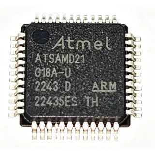
ATSAMD21G16B-AU - 48MHz ARM M0+ MCU 64KB Flash 48-TQFP | Microchip
MPN: ATSAMD21G16B-AU ✓ פעילATSAMD21G16B-AU סקירה
What is an ARM Cortex-M0+ microcontroller? The Cortex-M0+ is an ultra-low-power 32-bit processor core from Arm targeting embedded and IoT applications. Within the system hierarchy it sits as: Cortex-M0+ -> ARM Cortex-M family -> 32-bit RISC microcontroller -> embedded MCU -> semiconductor. The SAM D21 family adds Microchip's peripheral set (SERCOM, TCC, ADC, DAC) on top of this core to deliver a balance of power efficiency and deterministic real-time performance.
Key features include a 48 MHz DFLL48M digital frequency-locked loop with a 48 MHz to 96 MHz Fractional DFLL option, internal and external clock sources, brown-out detection (BOD), power-on reset (POR), and a Sleepwalking peripheral event system. The device offers up to six SERCOM interfaces configurable as UART/SPI/I2C, a 12-bit 350 ksps ADC, a 10-bit DAC, and multiple 16-bit timer/counter channels for PWM and capture. Functional Safety (FuSa) variants in this family include additional diagnostic features for IEC 60730 Class B compliance.
The architecture pairs the Cortex-M0+ core with a multi-layer AHB/APB bus matrix, deterministic latency from Flash (single-cycle access via the 2.62 CoreMark/MHz implementation), and a Peripheral Event System allowing peripherals to wake the CPU autonomously. The integrated Full-Speed USB 2.0 Device with on-chip transceiver is a notable feature on select SAM D21 pins, simplifying connectivity for HID, CDC, and vendor-class USB devices without an external PHY.
Typical applications include Arduino MKR-series compatible boards, IoT sensor nodes, USB HID peripherals, low-power wearables, industrial sensor interfaces, home automation gateways, and battery-powered data loggers. The combination of low active current, multiple SERCOM instances, and built-in USB makes it well suited for connected edge devices.
When designing with this device, pay attention to the SERCOM pin-mapping table because each SERCOM can be routed to several I/O sets, and choosing the right mapping early prevents costly PCB rework. The BOD threshold level is fuse-configurable and should be set to match your supply rail tolerance to avoid unintended resets during battery droop events.
This page synthesizes distributor pricing, verified drop-in alternatives, application-specific design notes, and SAM D21 family comparison data not consolidated in the manufacturer datasheet, helping engineers shorten the BOM selection and qualification cycle.
חלופות תחליף ישיר עבור ATSAMD21G16B-AU — אותו מארז, תואם פין-לפין. חלקים במארז שונה הדורשים עיבוד מחדש של ה-PCB אינם נכללים.
וריאנטים בסדרה זו
דגמים מאותה סדרה התואמים Drop-in עם ATSAMD21G16B-AU (אותו גורם צורה וטביעת רגל) — שונים ב ADC, Flash Memory, Operating Temperature, Package, DAC.
ATSAMD21G15B-AU
✅ Drop-Inצור קשר לקבלת מחיר
הצג גיליון נתונים ←ATSAMD21G18A-AU
✅ Drop-In✗ אזל מהמלאי
$2.78 / יחידה
הצג גיליון נתונים ←ATSAMD21G16B-AUT
✅ Drop-Inצור קשר לקבלת מחיר
הצג גיליון נתונים ←ATSAMD21G15B-AUT
✅ Drop-Inצור קשר לקבלת מחיר
הצג גיליון נתונים ←ATSAMD21G17D-AU
✅ Drop-In📋 חלופה להתייחסות (לא בקטלוג)
ATSAMD21G16B-AU דירוגים מרביים ומאפיינים חשמליים
| Core Architecture | ARM Cortex-M0+ (32-bit) |
| Family | SAM D21G |
| Maximum CPU Frequency | 48 MHz |
| CoreMark/MHz | 2.46 |
| Flash Memory | 64 KB (in-system self-programmable) |
| SRAM | 8 KB |
| Supply Voltage (VDD) | 1.62 V to 3.63 V |
| I/O Pins | 38 (maximum) |
| External Interrupts (EIC) | 16 |
| Debug Interface | Serial Wire Debug (SWD), 2-pin |
| מארז | 48-pin TQFP (7x7 mm) |
| טמפרטורת פעולה | -40 C to +85 C (industrial) |
| Hardware Multiplier | Single-cycle 32-bit |
| DFLL48M | 48 MHz Digital Frequency Locked Loop |
| סטטוס RoHS | Compliant (Green) |
| רמת MSL | MSL3 (per JEDEC J-STD-020) |
| Carrier Type | Tray |
| Brown-Out Detection | Yes, fuse-configurable |
תצורת פינים של ATSAMD21G16B-AU
| פין 1 | PA00 — I/O pin, SERCOM1 PAD0, ADC AIN0 |
| פין 2 | PA01 — I/O pin, SERCOM1 PAD1, ADC AIN1 |
| פין 3 | PA02 — I/O pin, SERCOM0 PAD0, AIN2, DAC VOUT |
| פין 4 | PA03 — I/O pin, SERCOM0 PAD1, AIN3, REF positive |
| פין 5 | PA04 — I/O pin, SERCOM0 PAD2, AIN4, VREF |
| פין 6 | PA05 — I/O pin, SERCOM0 PAD3, AIN5 |
| פין 7 | PA06 — I/O pin, SERCOM0 PAD0 alt, AIN6, alternative function |
| פין 8 | PA07 — I/O pin, SERCOM0 PAD1 alt, AIN7 |
| פין 9 | VDDCORE — Internal core voltage decoupling pin, requires 1 uF + 100 nF |
| פין 10 | GND — Common ground |
| פין 11 | VDDIN — Main digital supply input (1.62-3.63 V) |
| פין 12 | PA08 — I/O pin, SERCOM2 PAD0, NMI, ADC AIN16 |
| פין 13 | PA09 — I/O pin, SERCOM2 PAD1, AIN17 |
| פין 14 | PA10 — I/O pin, SERCOM2 PAD2, AIN18 |
| פין 15 | PA11 — I/O pin, SERCOM2 PAD3, AIN19 |
| פין 16 | PA12 — I/O pin, SERCOM4 PAD0 |
| פין 17 | PA13 — I/O pin, SERCOM4 PAD1 |
| פין 18 | PA14 — I/O pin, SERCOM4 PAD2, XIN32 |
| פין 19 | PA15 — I/O pin, SERCOM4 PAD3, XOUT32 |
| פין 20 | PA16 — I/O pin, SERCOM1 PAD0 alt, I2S SCK0 |
| פין 21 | PA17 — I/O pin, SERCOM1 PAD1 alt, I2S MCK0 |
| פין 22 | PA18 — I/O pin, SERCOM1 PAD2 alt, I2S FS0 |
| פין 23 | PA19 — I/O pin, SERCOM1 PAD3 alt, I2S SD0 |
| פין 24 | PA20 — I/O pin, SERCOM5 PAD2, I2S SD0 alt |
| פין 25 | PA21 — I/O pin, SERCOM5 PAD3, I2S FS0 alt |
| פין 26 | PA22 — I/O pin, SERCOM5 PAD0, I2S SCK0 alt, USB D- |
| פין 27 | PA23 — I/O pin, SERCOM5 PAD1, I2S MCK0 alt, USB D+ |
| פין 28 | PA24 — I/O pin, SERCOM3 PAD2, USB ID |
| פין 29 | PA25 — I/O pin, SERCOM3 PAD3, USB VBUS |
| פין 30 | GND — Common ground |
| פין 31 | VDDIO — I/O supply voltage input |
| פין 32 | PA26 — I/O pin |
| פין 33 | PA27 — I/O pin |
| פין 34 | PA28 — I/O pin, boot loader entry |
| פין 35 | PA29 — I/O pin |
| פין 36 | PA30 — I/O pin, SWD clock input on alt |
| פין 37 | PA31 — I/O pin, SWD data on alt |
| פין 38 | PB02 — I/O pin, SERCOM5 PAD0 alt, ADC AIN10 |
| פין 39 | PB03 — I/O pin, SERCOM5 PAD1 alt, ADC AIN11 |
| פין 40 | PB04 — I/O pin, SERCOM3 PAD0 alt, ADC AIN12 |
| פין 41 | PB05 — I/O pin, SERCOM3 PAD1 alt, ADC AIN13 |
| פין 42 | PB06 — I/O pin, SERCOM3 PAD2 alt, ADC AIN14 |
| פין 43 | PB07 — I/O pin, SERCOM3 PAD3 alt, ADC AIN15 |
| פין 44 | PB08 — I/O pin, SERCOM4 PAD0 alt, AIN2 alt |
| פין 45 | PB09 — I/O pin, SERCOM4 PAD1 alt, AIN3 alt |
| פין 46 | PB10 — I/O pin, SERCOM4 PAD2 alt |
| פין 47 | PB11 — I/O pin, SERCOM4 PAD3 alt |
| פין 48 | GND — Common ground (corner pin) |
יישומים טיפוסיים
ATSAMD21G16B-AU מתאים עבור 6 יישוםs: IoT Sensor Node / Edge Device, USB HID Peripheral / Consumer Dongle, Arduino-Compatible Development Platform, Wearable Fitness / Health Monitor, Industrial Sensor Interface / Modbus Node, Smart Home Lighting / DMX Controller.
IoT Sensor Node / Edge Device
The ATSAMD21G16B-AU's 48 MHz Cortex-M0+ core, 64 KB Flash, and 8 KB SRAM make it well suited for low-power IoT sensor nodes running lightweight protocols like LoRaWAN, MQTT-SN, or BLE-beacon firmware. Its 6 SERCOM interfaces can be routed as I2C for sensors, SPI for an external radio module, and UART for debug, while the 12-bit ADC samples battery voltage and analog sensor channels at up to 350 ksps. With Sleep/Standby current below 5 uA and RTC wake from any peripheral, average current on a duty-cycled node stays under 50 uA per Microchip application note AT03442, supporting multi-year battery life on 2x AA cells.
מומלץ
USB HID Peripheral / Consumer Dongle
The ATSAMD21G16B-AU integrates a Full-Speed USB 2.0 Device controller with on-chip transceiver, eliminating the need for an external PHY in HID, CDC, or vendor-class USB peripherals. Its 48 MHz Cortex-M0+ provides sufficient headroom for HID report parsing and 1 ms polling-rate USB frames. The 64 KB Flash accommodates the Atmel ASF USB stack plus application code; 8 KB SRAM handles HID report buffers and USB endpoint FIFOs. Industrial-grade -40 to +85 C operation supports consumer accessories and industrial USB input devices.
מומלץ
Arduino-Compatible Development Platform
The ATSAMD21G16B-AU powers the Arduino MKR GSM 1400, MKR WiFi 1010, and Arduino Zero boards, making it a de-facto standard for hobbyist and professional rapid-prototyping environments. Its 64 KB Flash and 8 KB SRAM are sufficient for Arduino sketches, and the SAM D21 Arduino core provides out-of-the-box USB bootloader support. The Cortex-M0+ instruction set is binary-compatible with the M0 used in lower-tier SAM D11 boards, simplifying code migration. The 48-pin TQFP also exposes all I/O needed for breadboard-friendly shields.
מומלץ
Wearable Fitness / Health Monitor
The ATSAMD21G16B-AU's small 48-pin TQFP footprint (7x7 mm), low active current around 4 mA at 48 MHz, and SERCOM-rich peripheral set suit battery-powered wearable designs such as fitness bands and heart-rate monitors. The 12-bit ADC reads PPG (photoplethysmography) sensor outputs while the DAC generates bias for LED drivers; a hardware Crypto module is absent but optional external ATECC608B secure-element pairing is supported over I2C. Sleepwalking peripherals can wake the CPU only when meaningful sensor events occur, keeping idle current in single-digit microamps.
מומלץ
Industrial Sensor Interface / Modbus Node
With its -40 C to +85 C industrial temperature rating and 38 GPIO, the ATSAMD21G16B-AU fits industrial Modbus RTU sensor interfaces and 4-20 mA loop-powered transmitters. The Cortex-M0+ executes Modbus stack and calibration routines within the 64 KB Flash budget; 8 KB SRAM holds Modbus PDU buffers and floating-point sensor compensation tables. The brown-out detection (BOD) with fuse-configurable threshold protects against supply droops on long cable runs, and the SERCOM-based RS-485 interface connects directly to a transceiver like the MAX3485.
מומלץ
Smart Home Lighting / DMX Controller
The ATSAMD21G16B-AU's 16-bit TCC timer/counter channels generate high-resolution PWM signals suitable for multi-channel RGBW LED dimming and DMX-512 lighting fixture control. Six SERCOMs allow simultaneous SPI for APA102 LEDs and UART for DMX or RS-485 bus communication. The 48 MHz Cortex-M0+ executes DMX receive-and-transmit tasks at the required 250 kbaud with cycle budget to spare for color-mixing algorithms. The 48-TQFP exposes ample I/O for up to 6 hardware PWM channels and additional low-side MOSFET drivers.
מומלץ
סיכום מוצרים מומלצים
נתוני עזר הנדסיים עבור ATSAMD21G16B-AU — השוואה, הנחיות תכנון ומידע על תאימות.
מדריך בחירה
השוואה עם חלופות
| פרמטר | מוצר זה | ATSAMD21G15B-AU | ATSAMD21G18A-AU | ATSAMD21G16B-AUT | ATSAMD21G17D-AU | ATSAMD21G15B-AUT |
|---|---|---|---|---|---|---|
| Package | 48-pin TQFP (7x7) | 48-pin TQFP (7x7) - same | 48-pin TQFP (7x7) - same | 48-pin TQFP (7x7) - same | 48-pin TQFP (7x7) - same | 48-pin TQFP (7x7) - same |
| Brand | Microchip Technology | Microchip Technology | Microchip Technology | Microchip Technology | Microchip Technology | Microchip Technology |
| Core | ARM Cortex-M0+ @ 48 MHz | ARM Cortex-M0+ @ 48 MHz | ARM Cortex-M0+ @ 48 MHz | ARM Cortex-M0+ @ 48 MHz | ARM Cortex-M0+ @ 48 MHz | ARM Cortex-M0+ @ 48 MHz |
| Flash | 64 KB | 32 KB | 256 KB | 64 KB | 128 KB | 32 KB |
| SRAM | 8 KB | 4 KB | 32 KB | 8 KB | 16 KB | 4 KB |
| Operating Voltage | 1.62 V to 3.63 V | 1.62 V to 3.63 V | 1.62 V to 3.63 V | 1.62 V to 3.63 V | 1.62 V to 3.63 V | 1.62 V to 3.63 V |
| Operating Temperature | -40 C to +85 C | -40 C to +85 C | -40 C to +85 C | -40 C to +85 C | -40 C to +85 C | -40 C to +85 C |
| Carrier Type | Tray | Tray | Tray | Tape & Reel | Tray | Tape & Reel |
| Unit Price (qty 1) | $3.95 | $3.45 | $4.85 | $3.95 | $4.40 | $3.45 |
מבדילים עיקריים
- Drop-in upgrade path to 256 KB Flash on identical footprint (לעומתATSAMD21G15B-AU)
- Tape and reel carrier without die change (לעומתATSAMD21G16B-AUT)
- Mid-density sweet spot with proven SAM D21 ecosystem (לעומתATSAMD21G17D-AU)
הערות תכנון
Place a 1 uF X7R ceramic decoupling capacitor as close as possible to the VDDCORE pin (pin 9) with a 100 nF X7R bypass in parallel; the internal 1.2 V core LDO requires this for stable operation across the full 1.62-3.63 V input range. VDDIN (pin 11) and VDDIO (pin 31) need their own 100 nF + 4.7 uF bulk capacitors. Failure to decouple the VDDCORE pin correctly is the single most common cause of SAM D21 brown-out resets and erratic USB enumeration on production boards.
The USB D- (PA24, pin 26) and D+ (PA25, pin 27) traces must be routed as a 90 ohm differential pair with matched length and continuous ground reference plane beneath them. Keep total trace length under 25 mm to stay within USB 2.0 Full-Speed signal-integrity budget. Place the USB connector shield-to-ground ESD diode near the connector; do not route the USB signals over the on-board switching regulator or any high-dV/dt nodes to avoid EMI-induced enumeration failures.
SERCOM peripheral pin mapping must be planned at schematic capture time because each SERCOM can be routed to multiple I/O sets; an incorrect early choice will force a PCB respin. Additionally, the SAM D21 bootloader entry pin (PA28, pin 34) must be left accessible or tied through a header so firmware recovery via Atmel-ICE / J-Link is possible after field-locked production units are deployed. Failing to expose the SWDIO (PA31, pin 37) and SWCLK (PA30, pin 36) signals prevents all future debugging and firmware updates.
מידע על תאימות
RoHS compliant Green per Microchip product page; not AEC-Q100 qualified (industrial grade -40 to +85 C only, automotive applications require SAM DA1 or SAM V71 family). REACH SVHC compliant per Microchip substance declaration. Halogen-free per Microchip Green package designation.