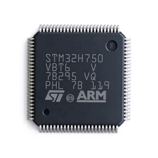
XMC4500F100F1024AC - 120MHz Cortex-M4 MCU 1024KB | Infineon
MPN: XMC4500F100F1024AC ✓ AktifXMC4500F100F1024AC Ringkasan
An ARM Cortex-M4 microcontroller is a 32-bit processor core that combines high-performance digital signal processing (DSP) instructions with a single-precision floating-point unit (FPU), commonly deployed in industrial automation, motor control, and power-conversion systems. The XMC4000 family extends this core with Infineon's proprietary peripheral set, bridging the CPU to power-management compute, motor-control compute, and connectivity ICs in the broader industrial semiconductor taxonomy.
Key features include a Cortex-M4 core with DSP/FPU at 120 MHz, 1024 KB Flash program memory, 160 KB SRAM, an integrated Ethernet MAC, USB 2.0 FS, six CAN nodes, six USIC channels configurable as UART/SPI/I2C, two 12-bit ADC units with up to 26 channels, a CCU6 timer unit for motor PWM, and a flexible peripheral interconnect (HRPWM). The LQFP-100 package is surface-mountable with standard 0.5 mm pitch.
The XMC4500 architecture pairs the Cortex-M4 core with a multi-layer bus matrix and dedicated peripheral DMA channels, enabling deterministic real-time response for power-conversion and motor-control loops. Embedded Flash supports in-application programming, and the on-board temperature sensor and supply-voltage monitor enable functional-safety-aware firmware designs.
Typical applications include industrial servo drives, solar inverters, switched-mode power supplies with digital control loops, field-oriented motor control (FOC), industrial PLC I/O modules, and EtherCAT/CANopen slave controllers. The combination of Cortex-M4 DSP capability and dedicated CCU6 PWM timers makes XMC4500 particularly well-suited to digital power conversion and three-phase motor control.
When designing with this part, allocate adequate decoupling (100 nF + 4.7 µF per VDD/VSS pair) and ensure that the 25 MHz crystal oscillator or external clock source meets the data sheet jitter specification. The 1024 KB Flash is split into two banks, allowing concurrent read/execute and in-field firmware updates via the built-in bootstrap loader.
This page consolidates Infineon datasheet specifications, distributor pricing and stock, drop-in compatible variants within the XMC4500 series, and practical design notes that are not aggregated in the standalone datasheet.
Alternatif penggantian untuk XMC4500F100F1024AC — paket yang sama, pin-pada-pin kompatibel. Bagian paket yang berbeda memerlukan kerja ulang PCB diabaikan.
Variasi di dalam seri ini
Model-series yang sama yang kompatibel dengan penggantian XMC4500F100F1024AC (sama faktor bentuk dan footprint) — berbeda di dalam ADC, Operating Temperature, Package, SRAM, CAN Nodes.
XMC4500F100K1024AC
✅ Drop-In📋 Alternatif referensi (tidak dalam katalog)
XMC4500F100F1024AA
✅ Drop-In📋 Alternatif referensi (tidak dalam katalog)
XMC4500F100F512AC
✅ Drop-In📋 Alternatif referensi (tidak dalam katalog)
XMC4500F100F1024ABXQMA1
✅ Drop-In📋 Alternatif referensi (tidak dalam katalog)
XMC4500F100K1024ACXQSA1
✅ Drop-InKontak untuk harga
Lihat Datasheet →STM32F407VGT6
✅ Drop-InKontak untuk harga
Lihat Datasheet →XMC4500F100F1024AC Rating Maksimal & Karakteristik Listrik
| Product Family | XMC4000 Series |
| Core Architecture | ARM Cortex-M4 with FPU and DSP instructions |
| Core Frequency | 120 MHz |
| Program Flash | 1024 KB |
| SRAM | 160 KB |
| Supply Voltage (VDD) | 3.13 V to 3.63 V |
| Paket | LQFP-100 (14x14 mm, 0.5 mm pitch) |
| Suhu Kerja | -40C to +85C (industrial) |
| Tipe Mounting | Surface Mount |
| Ethernet MAC | 10/100 Mbit integrated MAC (MII/RMII) |
| USB | USB 2.0 Full-Speed Device/Host |
| CAN Nodes | 6 (CAN 2.0B) |
| USIC Channels | 6 (UART/SPI/I2C/I2S configurable) |
| ADC | 2 x 12-bit, up to 26 channels, 2 MSPS |
| CCU6 PWM Units | 2 (motor control and power conversion) |
| DMA Channels | 12 (for peripheral-to-memory transfers) |
| Status RoHS | Compliant |
| Level MSL | 3 (168 hours) |
Konfigurasi Pin XMC4500F100F1024AC
| Pin produk 1 | VDD — Core supply voltage 3.3V |
| Pin produk 2 | VSS — Ground reference |
| Pin produk 3 | XTAL1 — Crystal oscillator input |
| Pin produk 4 | XTAL2 — Crystal oscillator output |
| Pin produk 5 | NRST — Reset input, active low |
| Pin produk 6 | TMS — SWD Test Mode Select |
| Pin produk 7 | TCK — SWD Test Clock |
| Pin produk 8 | TDI — SWD Test Data In |
| Pin produk 9 | TDO — SWD Test Data Out |
| Pin produk 10 | P0.0 — GPIO / alternate function |
| Pin produk 11 | P0.1 — GPIO / alternate function |
| Pin produk 12 | P0.2 — GPIO / alternate function |
| Pin produk 13 | P0.3 — GPIO / alternate function |
| Pin produk 14 | P0.4 — GPIO / alternate function |
| Pin produk 15 | P0.5 — GPIO / alternate function |
| Pin produk 16 | P0.6 — GPIO / alternate function |
| Pin produk 17 | P0.7 — GPIO / alternate function |
| Pin produk 18 | P0.9 — GPIO / alternate function |
| Pin produk 19 | P0.10 — GPIO / alternate function |
| Pin produk 20 | P0.11 — GPIO / alternate function |
| Pin produk 21 | P0.12 — GPIO / alternate function |
| Pin produk 22 | VSS — Ground reference |
| Pin produk 23 | VDD — Core supply voltage 3.3V |
| Pin produk 24 | P1.0 — GPIO / alternate function |
| Pin produk 25 | P1.1 — GPIO / alternate function |
| Pin produk 26 | P1.2 — GPIO / alternate function |
| Pin produk 27 | P1.3 — GPIO / alternate function |
| Pin produk 28 | P1.4 — GPIO / alternate function |
| Pin produk 29 | P1.5 — GPIO / alternate function |
| Pin produk 30 | P1.6 — GPIO / alternate function |
| Pin produk 31 | P1.7 — GPIO / alternate function |
| Pin produk 32 | P1.8 — GPIO / alternate function |
| Pin produk 33 | P1.9 — GPIO / alternate function |
| Pin produk 34 | P1.10 — GPIO / alternate function |
| Pin produk 35 | P1.11 — GPIO / alternate function |
| Pin produk 36 | P1.12 — GPIO / alternate function |
| Pin produk 37 | P1.13 — GPIO / alternate function |
| Pin produk 38 | P1.14 — GPIO / alternate function |
| Pin produk 39 | P1.15 — GPIO / alternate function |
| Pin produk 40 | VSS — Ground reference |
| Pin produk 41 | VDDP — Peripheral supply voltage 3.3V |
| Pin produk 42 | P2.0 — GPIO / alternate function |
| Pin produk 43 | P2.1 — GPIO / alternate function |
| Pin produk 44 | P2.2 — GPIO / alternate function |
| Pin produk 45 | P2.3 — GPIO / alternate function |
| Pin produk 46 | P2.4 — GPIO / alternate function |
| Pin produk 47 | P2.5 — GPIO / alternate function |
| Pin produk 48 | P2.6 — GPIO / alternate function |
| Pin produk 49 | P2.7 — GPIO / alternate function |
| Pin produk 50 | P2.8 — GPIO / alternate function |
| Pin produk 51 | P2.9 — GPIO / alternate function |
| Pin produk 52 | P2.10 — GPIO / alternate function |
| Pin produk 53 | P2.11 — GPIO / alternate function |
| Pin produk 54 | P2.12 — GPIO / alternate function |
| Pin produk 55 | P2.13 — GPIO / alternate function |
| Pin produk 56 | P2.14 — GPIO / alternate function |
| Pin produk 57 | P3.0 — GPIO / alternate function |
| Pin produk 58 | P3.1 — GPIO / alternate function |
| Pin produk 59 | P3.2 — GPIO / alternate function |
| Pin produk 60 | P3.3 — GPIO / alternate function |
| Pin produk 61 | P3.4 — GPIO / alternate function |
| Pin produk 62 | P3.5 — GPIO / alternate function |
| Pin produk 63 | P3.6 — GPIO / alternate function |
| Pin produk 64 | VSS — Ground reference |
| Pin produk 65 | VDD — Core supply voltage 3.3V |
| Pin produk 66 | P4.0 — GPIO / alternate function |
| Pin produk 67 | P4.1 — GPIO / alternate function |
| Pin produk 68 | P4.2 — GPIO / alternate function |
| Pin produk 69 | P4.3 — GPIO / alternate function |
| Pin produk 70 | P4.4 — GPIO / alternate function |
| Pin produk 71 | P4.5 — GPIO / alternate function |
| Pin produk 72 | P4.6 — GPIO / alternate function |
| Pin produk 73 | P4.7 — GPIO / alternate function |
| Pin produk 74 | P4.8 — GPIO / alternate function |
| Pin produk 75 | P4.9 — GPIO / alternate function |
| Pin produk 76 | P5.0 — GPIO / alternate function |
| Pin produk 77 | P5.1 — GPIO / alternate function |
| Pin produk 78 | P5.2 — GPIO / alternate function |
| Pin produk 79 | P5.3 — GPIO / alternate function |
| Pin produk 80 | P5.4 — GPIO / alternate function |
| Pin produk 81 | P5.5 — GPIO / alternate function |
| Pin produk 82 | P5.6 — GPIO / alternate function |
| Pin produk 83 | P5.7 — GPIO / alternate function |
| Pin produk 84 | P5.8 — GPIO / alternate function |
| Pin produk 85 | P5.9 — GPIO / alternate function |
| Pin produk 86 | VDDP — Peripheral supply voltage 3.3V |
| Pin produk 87 | VSS — Ground reference |
| Pin produk 88 | USB_DP — USB 2.0 Full-Speed D+ |
| Pin produk 89 | USB_DM — USB 2.0 Full-Speed D- |
| Pin produk 90 | ETH_TX_P — Ethernet MAC MII/RMII transmit positive |
| Pin produk 91 | ETH_TX_N — Ethernet MAC MII/RMII transmit negative |
| Pin produk 92 | ETH_RX_P — Ethernet MAC MII/RMII receive positive |
| Pin produk 93 | ETH_RX_N — Ethernet MAC MII/RMII receive negative |
| Pin produk 94 | CAN1_RX — CAN node 1 receive |
| Pin produk 95 | CAN1_TX — CAN node 1 transmit |
| Pin produk 96 | CAN2_RX — CAN node 2 receive |
| Pin produk 97 | CAN2_TX — CAN node 2 transmit |
| Pin produk 98 | ADC0_CH0 — 12-bit ADC channel 0 |
| Pin produk 99 | ADC0_CH1 — 12-bit ADC channel 1 |
| Pin produk 100 | ADC0_CH2 — 12-bit ADC channel 2 |
Aplikasi Umum
XMC4500F100F1024AC cocok untuk 6 aplikasis: Industrial Servo Drives, Digital Power Conversion (SMPS Controllers), Solar Inverters and PV String Optimizers, Industrial PLC I/O Modules, Field-Oriented Motor Control (FOC) for EV and Robotics, Building Automation Controllers (BACnet / Modbus).
Industrial Servo Drives
The XMC4500F100F1024AC is well suited to industrial servo drives because its dual CCU6 timer units generate the six complementary PWM signals required for three-phase motor control. The Cortex-M4 core with FPU and DSP instructions at 120 MHz provides the computational throughput for field-oriented control (FOC) loops within the typical 16 kHz cycle. The 6 CAN nodes and integrated Ethernet MAC enable EtherCAT, CANopen, or PROFINET slave connectivity for industrial servo drives in factory automation systems.
Direkomendasikan
Digital Power Conversion (SMPS Controllers)
The XMC4500F100F1024AC fits digital power conversion applications because of its HRPWM unit (high-resolution PWM), 12-bit 2 MSPS ADCs, and Cortex-M4F performance at 120 MHz for closed-loop control math. Dual 12-bit ADC units with up to 26 channels enable simultaneous voltage and current sensing across multi-phase topologies. Infineon's DAVE firmware ecosystem provides reference vector control libraries and digital PFC code, accelerating time-to-market for solar inverters, telecom rectifiers, and digital LED drivers.
Direkomendasikan
Solar Inverters and PV String Optimizers
The XMC4500F100F1024AC fits solar inverters and PV string optimizers because its HRPWM delivers fine-grained duty-cycle resolution for MPPT and grid-tie inverter control loops. The 1024 KB Flash stores both the application code and grid-tie support libraries, and the Ethernet MAC enables Modbus TCP or Sunspec communication for monitoring. Six CAN nodes connect to module-level electronics. Operating temperature range of -40C to +85C supports rooftop inverter enclosures under direct solar exposure.
Direkomendasikan
Industrial PLC I/O Modules
The XMC4500F100F1024AC fits industrial PLC I/O modules because of its six CAN nodes for CANopen I/O expansion, six USIC channels for RS-485/RS-232 sensor connectivity, and integrated Ethernet MAC for PROFINET/EtherNet/IP slave interfaces. The 160 KB SRAM supports large process-image buffers for high-density digital I/O modules, and the 1024 KB Flash enables on-board Modbus, PROFIBUS, or EtherCAT slave stacks without external memory expansion. Wide -40C to +85C industrial temperature range supports cabinet-mounted control cabinets.
Direkomendasikan
Field-Oriented Motor Control (FOC) for EV and Robotics
The XMC4500F100F1024AC fits FOC motor control in robotics and small electric vehicles because its Cortex-M4F core handles FOC math (Park/Clarke transforms, SVM) within tight control cycles, while dedicated CCU6 timers produce the six PWM channels with dead-time insertion. Dual 12-bit ADCs synchronously sample phase currents at the PWM centre point. The CAN bus interface integrates with vehicle CAN networks, and the wide operating temperature supports automotive under-hood environments in appropriate sealed enclosures.
Direkomendasikan
Building Automation Controllers (BACnet / Modbus)
The XMC4500F100F1024AC fits building automation controllers because its six USIC channels support RS-485 BACnet MS-TP or Modbus RTU fieldbus connectivity, while the Ethernet MAC enables BACnet/IP or Modbus TCP communication on the building network. The Cortex-M4F performance runs multiple protocol stacks simultaneously. The 1024 KB Flash stores application firmware, BACnet/Modbus stacks, and webserver interfaces for HVAC, lighting, and access control panels across commercial buildings and data centres.
Direkomendasikan
Ringkasan Produk Direkomendasikan
Data referensi engineering untuk XMC4500F100F1024AC — pembandingan, panduan desain, dan informasi konformitas.
Panduan Pemilihan
Pembandingan dengan Alternatif
| Parameter Umum | Produk Ini | XMC4500F100K1024AC | XMC4500F100F1024AA | XMC4500F100F512AC | XMC4500F100F1024ABXQMA1 | XMC4500F100K1024ACXQSA1 | STM32F407VGT6 |
|---|---|---|---|---|---|---|---|
| Brand | Infineon | Infineon | Infineon | Infineon | Infineon | Infineon | STMicroelectronics |
| Package | LQFP-100 | LQFP-100 | LQFP-100 | LQFP-100 | LQFP-100 | LQFP-100 | LQFP-100 |
| Core | ARM Cortex-M4F 120 MHz | ARM Cortex-M4F 120 MHz | ARM Cortex-M4F 120 MHz | ARM Cortex-M4F 120 MHz | ARM Cortex-M4F 120 MHz | ARM Cortex-M4F 120 MHz | ARM Cortex-M4F 168 MHz |
| Flash Memory | 1024 KB | 1024 KB | 1024 KB | 512 KB | 1024 KB | 1024 KB | 1024 KB |
| SRAM | 160 KB | 160 KB | 160 KB | 160 KB | 160 KB | 160 KB | 192 KB |
| Ethernet MAC | Yes (MII/RMII) | Yes (MII/RMII) | Yes (MII/RMII) | Yes (MII/RMII) | Yes (MII/RMII) | Yes (MII/RMII) | Yes (MII/RMII) |
| CAN Nodes | 6 | 6 | 6 | 6 | 6 | 6 | 2 (bxCAN) |
| CCU6 PWM Units | 2 | 2 | 2 | 2 | 2 | 2 | No CCU6; uses general-purpose timers |
Diferensiator Kunci
- Dedicated CCU6 and HRPWM timer blocks for digital power conversion (vsSTM32F407VGT6)
- Six native CAN 2.0B nodes for industrial multi-bus applications (vsSTM32F407VGT6)
- Native 10/100 Ethernet MAC with MII/RMII without external bridge ICs (vsXMC4300-F100F256)
Catatan Desain
Decouple every VDD and VDDP pin with a 100 nF X7R ceramic capacitor placed within 5 mm of the respective supply pin, plus one bulk 4.7 µF ceramic per supply rail. The XMC4500 has separate core (VDD) and I/O (VDDP) supplies that must both be powered during normal operation. Power-on-reset behaviour and NRST hold timing are defined in the Infineon datasheet; ensure VDDP and VDD rise within 10 ms of each other to avoid undefined peripheral state.
Place the 25 MHz crystal or external clock source within 5 mm of the XTAL1/XTAL2 pins and guard the traces with a ground pour on both sides of the PCB. Route USB_DP/USB_DM as a 90-ohm differential pair and Ethernet MII/RMII signals as 50-ohm single-ended or 100-ohm differential pairs. Avoid routing high-speed signals (USB, Ethernet, HRPWM) directly under or above the crystal traces to minimise crosstalk.
The LQFP-100 package has a junction-to-ambient thermal resistance (theta_JA) of approximately 40 C/W on a 2-layer PCB with modest copper. At maximum CPU activity (120 MHz, all peripherals active), power dissipation is in the order of 200-300 mW, giving a junction temperature rise of 8-12 C above ambient. No heatsink is required for typical industrial applications. Designers should validate thermal behaviour in fully sealed enclosures where convection is limited.
Common pitfalls with XMC4500 include: (1) forgetting that VDDP must be present for any GPIO to operate, even when the core is held in standby; (2) failing to configure the boot mode pins before reset release, which can lock the device into an unexpected boot mode; (3) using the wrong CAN transceiver voltage class (XMC4500 CAN I/O is 3.3V); (4) neglecting to enable the peripheral clock before accessing peripheral registers, which causes silent bus faults. Always refer to the Infineon reference manual register descriptions.
For 100 Mbps Ethernet via MII, route TX_CLK, RX_CLK, TXD[3:0], RXD[3:0], TX_EN, RX_ER, CRS_DV as 50-ohm single-ended traces to a length-matched bus within 50 mm of the RJ45 magnetics. For RMII, route the 50 MHz reference clock with strict length matching to all RMII signals. Place the Ethernet PHY's 25 MHz crystal close to the PHY and provide a clean, isolated ground reference. Do not share switching power-supply grounds with the Ethernet PHY grounds.
Informasi Konformitas
RoHS compliant per Infineon product page. Not AEC-Q100 qualified - for automotive applications consider XMC4400 or AURIX series. Industrial-grade temperature range -40C to +85C confirmed by F-grade ordering designation.