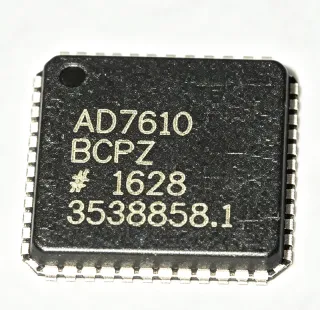
AD9265 - 16-Bit 125 MSPS ADC | Analog Devices | Communications
部品番号: AD9265 ✓ 生産中| 数量 | 単価 | 小計 |
|---|---|---|
| 1 | $45.32 | $45.32 |
| 10 | $41.87 | $418.70 |
| 100 | $36.54 | $3,654.00 |
| 500 | $32.1 | $16,050.00 |
| 1,000 | $28.75 | $28,750.00 |
AD9265 概要
An analog-to-digital converter (ADC) is a critical component in signal processing chains, converting continuous analog signals into discrete digital values for processing by digital systems. The AD9265 belongs to the family of high-speed, high-resolution ADCs, which are essential in applications such as software-defined radios, radar systems, and medical imaging. Its 16-bit resolution and 125 MSPS sampling rate enable precise digitization of wideband signals, balancing speed and accuracy.
Key features of the AD9265 include a 16-bit resolution, sampling rates of 125 MSPS, 105 MSPS, and 80 MSPS variants, and a 1.8 V supply voltage. It offers high SNR and SFDR, making it ideal for demanding communications systems. The device also includes a differential input, a CMOS or LVDS output interface, and a flexible SPI port for configuration. Its low power dissipation and small package footprint enhance system integration.
Technically, the AD9265 employs a pipelined ADC architecture, which allows high-speed conversion while maintaining high resolution. The device integrates a sample-and-hold amplifier, a reference voltage, and digital error correction, ensuring accurate conversion across the full input range. The output data can be formatted in either offset binary or two's complement, providing flexibility for various digital interfaces.
Typical applications include communications receivers, radar systems, medical ultrasound, and test and measurement equipment. In communications, the AD9265's high SNR and SFDR enable reliable demodulation of complex modulated signals. In radar, its high sampling rate captures fast-rising pulses with precision. In medical imaging, the 16-bit resolution ensures fine detail in ultrasound images.
When designing with the AD9265, ensure proper decoupling of the analog and digital supplies, and use a low-jitter clock source to maximize SNR. The differential input should be driven with a balanced source to achieve optimal performance. The SPI port allows adjustment of output format and test modes, which can be used to verify system integrity.
ドロップイン代替品: AD9265 — 同一パッケージでピン互換。PCBの作り直しが必要な異なるパッケージの部品は除外されています。
クイック比較ツール — 並列比較する代替部品を選択:
AD9265BCPZ-105
✅ ドロップイン📋 参考代替品(カタログ未掲載)
AD9265BCPZ-125
✅ ドロップイン📋 参考代替品(カタログ未掲載)
AD9265BCPZ-80
✅ ドロップイン ⚠️ 仕様未検証📋 参考代替品(カタログ未掲載)
LTC2208
✅ ドロップイン ⚠️ 仕様未検証📋 参考代替品(カタログ未掲載)
ADS4249
✅ ドロップイン ⚠️ 仕様未検証📋 参考代替品(カタログ未掲載)
AD9265 最大定格&電気的特性
| 分解能 | 16 bits |
| サンプリングレート | 125 MSPS (also 105 MSPS, 80 MSPS variants) |
| Number of Inputs | 1 |
| Input Type | Differential |
| Data Interface | CMOS or LVDS |
| Architecture | Pipelined |
| 電源電圧 | 1.8 V |
| パッケージ | 48-LFCSP-VQ (7x7 mm) |
| 実装タイプ | Surface Mount |
| RoHS ステータス | Compliant |
| Number of Converters | 1 |
AD9265 ピン構成
| ピン 1 | AVDD — Analog supply voltage (1.8 V) |
| ピン 2 | VIN+ — Positive differential analog input |
| ピン 3 | VIN- — Negative differential analog input |
| ピン 4 | AVSS — Analog ground |
| ピン 5 | CLK+ — Positive clock input |
| ピン 6 | CLK- — Negative clock input |
| ピン 7 | DVDD — Digital supply voltage (1.8 V) |
| ピン 8 | DVSS — Digital ground |
| ピン 9 | D0 — Digital output bit 0 (LSB) |
| ピン 10 | D1 — Digital output bit 1 |
| ピン 11 | D2 — Digital output bit 2 |
| ピン 12 | D3 — Digital output bit 3 |
| ピン 13 | D4 — Digital output bit 4 |
| ピン 14 | D5 — Digital output bit 5 |
| ピン 15 | D6 — Digital output bit 6 |
| ピン 16 | D7 — Digital output bit 7 |
| ピン 17 | D8 — Digital output bit 8 |
| ピン 18 | D9 — Digital output bit 9 |
| ピン 19 | D10 — Digital output bit 10 |
| ピン 20 | D11 — Digital output bit 11 |
| ピン 21 | D12 — Digital output bit 12 |
| ピン 22 | D13 — Digital output bit 13 |
| ピン 23 | D14 — Digital output bit 14 |
| ピン 24 | D15 — Digital output bit 15 (MSB) |
| ピン 25 | SCLK — SPI clock input |
| ピン 26 | SDIO — SPI data input/output |
| ピン 27 | CSB — SPI chip select (active low) |
| ピン 28 | PDWN — Power-down control (active high) |
| ピン 29 | SYNC — Synchronization input |
| ピン 30 | OEB — Output enable (active low) |
| ピン 31 | VREF — Voltage reference output |
| ピン 32 | SENSE — Reference mode select |
| ピン 33 | REFB — Reference bottom |
| ピン 34 | REFT — Reference top |
| ピン 35 | CML — Common-mode level output |
| ピン 36 | VCM — Common-mode voltage output |
| ピン 37 | AVDD — Analog supply voltage (1.8 V) |
| ピン 38 | AVSS — Analog ground |
| ピン 39 | AVSS — Analog ground |
| ピン 40 | AVDD — Analog supply voltage (1.8 V) |
| ピン 41 | DVDD — Digital supply voltage (1.8 V) |
| ピン 42 | DVSS — Digital ground |
| ピン 43 | DVSS — Digital ground |
| ピン 44 | DVDD — Digital supply voltage (1.8 V) |
| ピン 45 | NC — No connect |
| ピン 46 | NC — No connect |
| ピン 47 | NC — No connect |
| ピン 48 | NC — No connect |
主な用途
AD9265 の用途: 6 件s: Communications Receivers, Radar Systems, Medical Ultrasound, Test and Measurement, Software-Defined Radio, Communications Infrastructure.
Communications Receivers
The AD9265 is ideal for communications receivers due to its high SNR and SFDR, enabling reliable demodulation of complex modulated signals. Its 125 MSPS sampling rate supports wideband signals, and the 16-bit resolution ensures high dynamic range. The device's low power consumption is beneficial for multi-channel systems. In a typical receiver chain, the AD9265 digitizes the IF signal after downconversion, providing a digital output for baseband processing. The differential input and LVDS output interface simplify connection to FPGAs or DSPs. The SPI port allows configuration of output format and test modes, enhancing system flexibility.
おすすめ
Radar Systems
In radar systems, the AD9265's high sampling rate and 16-bit resolution enable precise digitization of radar returns, improving target detection and range resolution. The device's high SFDR minimizes spurious signals that could be mistaken for targets. The 1.8 V supply and low power dissipation are advantageous for phased-array radar modules. The AD9265 can be used in both pulsed and continuous-wave radar architectures. Its pipelined architecture ensures low latency, which is critical for real-time processing. The LVDS output interface provides high-speed data transfer to processing units.
おすすめ
Medical Ultrasound
The AD9265 is well-suited for medical ultrasound systems, where high resolution and low noise are essential for image quality. The 16-bit resolution provides fine amplitude detail, while the 125 MSPS sampling rate captures high-frequency ultrasound echoes. The device's low power consumption is important for portable ultrasound devices. In an ultrasound receiver, the AD9265 digitizes the echo signal after beamforming, enabling digital signal processing for image reconstruction. The differential input reduces common-mode noise, improving signal integrity. The SPI port allows adjustment of output data format to match the processing chain.
おすすめ
Test and Measurement
The AD9265 is used in test and measurement equipment such as oscilloscopes and spectrum analyzers, where high bandwidth and accuracy are required. Its 125 MSPS sampling rate and 16-bit resolution enable precise digitization of signals up to tens of MHz. The device's high SNR ensures accurate measurements of small signals. In a digital oscilloscope, the AD9265 digitizes the input signal after attenuation and amplification, providing a digital representation for display and analysis. The LVDS output interface supports high-speed data transfer to the acquisition system. The SPI port enables configuration of test modes for calibration.
おすすめ
Software-Defined Radio
The AD9265 is a key component in software-defined radios (SDR), where it digitizes wideband RF signals for digital processing. Its high sampling rate and 16-bit resolution enable the capture of multiple channels simultaneously. The device's high SFDR ensures that weak signals are not masked by spurious tones. In an SDR receiver, the AD9265 digitizes the IF signal after downconversion, allowing flexible demodulation in software. The LVDS output interface provides a high-speed digital stream to an FPGA or DSP. The SPI port allows dynamic reconfiguration of the ADC for different operating modes.
おすすめ
Communications Infrastructure
The AD9265 is used in communications infrastructure such as base stations and microwave links, where high performance and reliability are critical. Its 16-bit resolution and 125 MSPS sampling rate support high-capacity data transmission. The device's low power consumption reduces heat dissipation in dense equipment. In a base station receiver, the AD9265 digitizes multiple carriers simultaneously, enabling digital predistortion and interference cancellation. The differential input and LVDS output interface simplify connection to digital processors. The SPI port allows configuration of output data format and test modes for system calibration.
おすすめ
おすすめ製品の概要
エンジニアリング参考データ: AD9265 — 比較、設計ガイダンス、コンプライアンス情報。
選定ガイド
代替品との比較
| パラメータ | この製品 | AD9265BCPZ-105 | AD9265BCPZ-125 | AD9265BCPZ-80 | LTC2208 | ADS4249 |
|---|---|---|---|---|---|---|
| Package | 48-LFCSP-VQ (7x7) | 48-LFCSP-VQ (7x7) | 48-LFCSP-VQ (7x7) | 48-LFCSP-VQ (7x7) | 48-LFCSP-VQ (7x7) | 48-LFCSP-VQ (7x7) |
| Brand | Analog Devices | Analog Devices | Analog Devices | Analog Devices | Analog Devices | Texas Instruments |
| Resolution | 16 bits | 16 bits | 16 bits | 16 bits | 16 bits | 16 bits |
| Sampling Rate | 125 MSPS | 105 MSPS | 125 MSPS | 80 MSPS | 130 MSPS | 250 MSPS |
| Supply Voltage | 1.8 V | 1.8 V | 1.8 V | 1.8 V | 1.8 V | 1.8 V |
| Input Type | Differential | Differential | Differential | Differential | Differential | Differential |
| Data Interface | CMOS or LVDS | CMOS or LVDS | CMOS or LVDS | CMOS or LVDS | LVDS | LVDS |
| Architecture | Pipelined | Pipelined | Pipelined | Pipelined | Pipelined | Pipelined |
主な差別化要因
- High sampling rate with 16-bit resolution (vs AD9265BCPZ-105)
- Low power consumption (vs LTC2208)
- Flexible output interface (vs ADS4249)
設計ノート
The AD9265 requires a clean 1.8 V supply for both analog and digital domains. Use separate analog and digital supply pins with proper decoupling. Place 0.1 uF and 10 uF capacitors close to each supply pin to filter high-frequency noise. A ferrite bead can be used to isolate the analog supply from digital switching noise.
For optimal performance, use a solid ground plane and partition the PCB into analog and digital sections. The analog input traces should be kept short and shielded to minimize noise pickup. The clock input should be routed with controlled impedance and kept away from digital outputs to avoid crosstalk.
The differential analog input should be driven with a balanced source to achieve the best SNR and SFDR. Use a transformer or a differential amplifier to convert single-ended signals to differential. Ensure the common-mode voltage is set to the specified VCM level. The clock source must have low jitter to avoid degrading the SNR.
コンプライアンス情報
RoHS compliant per Analog Devices product page. No AEC-Q100 qualification for this ADC.