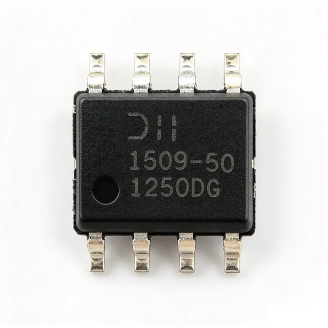
AP1509-50SG-13 - 2A, 150kHz, Fixed 5V Buck Converter | Diodes Inc.
部品番号: AP1509-50SG-13 ✓ 生産中| 数量 | 単価 | 小計 |
|---|---|---|
| 1 | $0.4219 | $0.42 |
| 10 | $0.3047 | $3.05 |
| 100 | $0.2695 | $26.95 |
| 500 | $0.2578 | $128.90 |
| 1,000 | $0.2461 | $246.10 |
AP1509-50SG-13 概要
A buck (step-down) DC-DC converter is a switching voltage regulator that uses an inductor-capacitor energy transfer network to convert a higher DC input into a lower, regulated DC output. Buck regulators deliver far higher efficiency (typically 80-95%) than linear regulators when the input-to-output voltage drop is large, which makes them the preferred topology for stepping down 12 V or 15 V bus rails to logic-level supplies such as 5 V, 3.3 V or 1.8 V. The AP1509-50SG-13 sits in the broader hierarchy of switching regulator -> DC-DC converter -> voltage regulator -> power management IC.
Key specifications include a fixed 5 V output, 150 kHz nominal switching frequency, 2 A continuous output current, 4.5 V to 22 V input voltage range, internal MOSFET switch, and built-in thermal shutdown. The 150 kHz switching frequency allows the use of small, low-cost inductors and filter capacitors, while the SOIC-8 footprint offers the same land pattern as the popular LM2596-style 5-pin regulators with a few unused pins. This pin/effort savings is one of the device's primary value propositions.
Typical applications include 12 V-to-5 V distributed power buses in consumer electronics, point-of-load regulation after a front-end AC-DC or 24 V industrial supply, battery charger auxiliaries, hobby robotics and Arduino-style 5 V rails, and any cost-sensitive board that previously used an LM7805 linear regulator and now needs higher efficiency. Designers moving from a 7805 typically see efficiency jump from ~40% to ~85% while reducing or eliminating heatsinking.
When designing with this part, observe the minimum 4.5 V input headroom and choose an inductor sized for the 2 A saturation rating with low DCR for best efficiency. The AP1509 uses voltage-mode control; for noise-sensitive analog loads a small LC output filter or post-LDO can be added because the ripple at 150 kHz is typically 30-50 mV pk-pk.
ドロップイン代替品: AP1509-50SG-13 — 同一パッケージでピン互換。PCBの作り直しが必要な異なるパッケージの部品は除外されています。
クイック比較ツール — 並列比較する代替部品を選択:
AP1509-33SG-13
📋 参考代替品(カタログ未掲載)
AP1509-12SG-13
📋 参考代替品(カタログ未掲載)
AP1509-33SL-13
📋 参考代替品(カタログ未掲載)
AP1513
📋 参考代替品(カタログ未掲載)
LM2596S-5.0
📋 参考代替品(カタログ未掲載)
AP1509-50SG-13 最大定格&電気的特性
| トポロジー | Buck (Step-Down) |
| 機能 | PWM Switching Regulator |
| 出力構成 | Positive, Fixed |
| 出力電圧 | 5.0 V |
| 入力電圧範囲 | 4.5 V to 22 V |
| Output Current | 2 A |
| スイッチング周波数 | 150 kHz |
| 出力数 | 1 |
| 同期整流器 | No (asynchronous) |
| パッケージ | 8-SOIC (SO-8, 3.90 mm body width) |
| 実装タイプ | Surface Mount |
| Internal Switch | Yes (integrated power MOSFET) |
| Feedback Method | Fixed output (internal resistor divider) |
| RoHS ステータス | Compliant |
AP1509-50SG-13 ピン構成
| ピン 1 | VIN — Input voltage supply (4.5 V to 22 V) |
| ピン 2 | SW — Switch node - connect to external inductor and Schottky diode |
| ピン 3 | GND — Ground return |
| ピン 4 | FB — Feedback (internally set for fixed 5 V output) |
| ピン 5 | NC — Not connected (per datasheet) |
| ピン 6 | COMP — Compensation network node |
| ピン 7 | NC — Not connected (per datasheet) |
| ピン 8 | VCC — Internal regulator VCC (decouple with 1 uF) |
主な用途
AP1509-50SG-13 の用途: 6 件s: 12 V to 5 V Distributed Power Bus, Linear-Regulator Replacement (7805 Substitute), Industrial 24 V Bus to 5 V Conversion, Battery Charger Auxiliary Supply, Hobby / Arduino-Style 5 V Rail, Appliance and White-Goods Power.
12 V to 5 V Distributed Power Bus
The AP1509-50SG-13 is a natural choice for stepping a 12 V or 15 V system bus down to a regulated 5 V rail at up to 2 A. Its 150 kHz PWM allows the use of small ceramic input/output capacitors and a 33 uH inductor, and the integrated MOSFET eliminates external switches, reducing BOM cost and PCB area compared to a controller+MOSFET design. Place the inductor and Schottky diode close to pins 1-3 of the SO-8, and use a 100 uF low-ESR cap on VOUT to minimize ripple.
おすすめ
Linear-Regulator Replacement (7805 Substitute)
Replacing a TO-220 LM7805 with the AP1509-50SG-13 typically lifts efficiency from ~40% to ~85% at 12 V-to-5 V/1 A, and eliminates the bulky heatsink. The SO-8 footprint occupies less than half the board area of a TO-220, freeing space for portable and consumer designs. Add a Schottky diode (e.g., B340A) at the switch node and a 33 uH inductor; the result is a cooler, smaller, longer-battery-life 5 V supply.
おすすめ
Industrial 24 V Bus to 5 V Conversion
The 22 V absolute-max input of the AP1509-50SG-13 makes it marginal for true 24 V industrial rails; however, with a small front-end Zener or TVS clamp (e.g., 22 V SMAJ) and a fuse, the part reliably steps down 24 V nominal to 5 V for PLC I/O, sensor conditioning, and HMI displays. The 2 A capability covers most PLC digital-output cards, and the 150 kHz fundamental stays clear of typical industrial 4-20 mA loop bandwidths, minimizing conducted EMI.
おすすめ
Battery Charger Auxiliary Supply
In lead-acid or multi-cell Li-ion charger designs, the AP1509-50SG-13 provides a stable 5 V rail for the charger MCU, fan driver, and status LEDs from a 12-18 V battery stack. The high 22 V input headroom tolerates load-dump transients in automotive and forklift applications when paired with a TVS, and the fixed 5 V output removes the need for a feedback divider. Designers should derate to 1.5 A continuous at high ambient temperatures.
おすすめ
Hobby / Arduino-Style 5 V Rail
The 2 A output of the AP1509-50SG-13 comfortably powers an Arduino Mega plus several sensors, NeoPixel strips, and small servos from a 9 V or 12 V wall adapter. The SO-8 package fits on a typical perfboard or custom shield, and the 150 kHz frequency does not interfere with 50/60 Hz mains or 433 MHz RF links. A simple 33 uH inductor + 220 uF output cap provides clean 5 V with <50 mV pk-pk ripple.
おすすめ
Appliance and White-Goods Power
Inside washing machines, microwave ovens, and air-conditioner control boards, the AP1509-50SG-13 derives the 5 V logic rail from a 12 V or 15 V aux winding. Its wide 4.5-22 V input tolerates rectified mains variations, while thermal shutdown protects against blocked-fan overtemperature conditions. The fixed 5 V output feeds MCU, relay drivers, and user-interface displays without external adjustment.
おすすめ
おすすめ製品の概要
エンジニアリング参考データ: AP1509-50SG-13 — 比較、設計ガイダンス、コンプライアンス情報。
選定ガイド
代替品との比較
| パラメータ | この製品 | AP1509-33SG-13 | AP1509-12SG-13 | AP1509-33SL-13 | AP1513 | LM2596S-5.0 |
|---|---|---|---|---|---|---|
| Brand | Diodes Incorporated | Diodes Incorporated | Diodes Incorporated | Diodes Incorporated | Diodes Incorporated | Texas Instruments |
| Package | 8-SOIC (SO-8) | 8-SOIC (SO-8) - same | 8-SOIC (SO-8) - same | SOP-8L - same | 8-SOIC (SO-8) - same | TO-263-5 - different (not same footprint) |
| Output Voltage | 5.0 V fixed | 3.3 V fixed | 12 V fixed | 3.3 V fixed | Adjustable 1.23 V to VIN | 5.0 V fixed |
| Output Current | 2 A | 2 A | 2 A | 2 A | 3 A | 3 A |
| Input Voltage Range | 4.5 V to 22 V | 4.5 V to 22 V | 4.5 V to 22 V | 4.5 V to 22 V | 4.5 V to 23 V | 4.5 V to 40 V |
| Switching Frequency | 150 kHz | 150 kHz | 150 kHz | 150 kHz | 300 kHz | 150 kHz |
| Topology | Async Buck | Async Buck | Async Buck | Async Buck | Async Buck | Async Buck |
| Adjustable Output | No (fixed 5.0 V) | No (fixed 3.3 V) | No (fixed 12 V) | No (fixed 3.3 V) | Yes (external resistor divider) | No (fixed 5.0 V) |
| RoHS Compliance | Yes | Yes | Yes | Yes | Yes | Yes |
主な差別化要因
- Compact SO-8 footprint with integrated power MOSFET (vs LM2596S-5.0)
- Wide input range with simple fixed-output architecture (vs AP1513)
- Family-wide pin compatibility across all output voltages (vs AP1509-33SL-13)
設計ノート
Place the input capacitor (10 uF ceramic + 100 uF electrolytic bulk), the 33 uH inductor, and the Schottky diode (B340A or equivalent, 3 A rated) as close as possible to the AP1509-50SG-13's pins 1-3. Keep the switch-node (pin 2) trace short and away from sensitive analog traces. Use a ground pour on the top layer stitched with multiple vias to the inner ground plane to minimize parasitic inductance.
Estimated: at 12 V input, 5 V output, and 2 A load, the AP1509-50SG-13 dissipates approximately (12 V - 5 V) x 2 A = 14 W in the linear region of the switch and Schottky; the SO-8 has limited thermal performance. In practice, conduction loss in the internal MOSFET and the external Schottky dominate, and at full 2 A continuous load the device will likely enter thermal shutdown without a substantial copper-pour heatsink (>= 1 sq inch) or airflow.
Do not exceed the 22 V absolute-maximum input - add a TVS clamp (e.g., SMAJ22A) if the input is a 24 V industrial bus or comes from a long cable with inductive kickback. Do not omit the external Schottky diode; the AP1509 relies on an external asynchronous rectifier. Choose an inductor with >= 3 A saturation current and low DCR (< 50 mOhm) to maintain efficiency. Finally, do not place ceramic output capacitors directly at the feedback pin - the loop compensation expects a moderate ESR.
コンプライアンス情報
RoHS compliant per Diodes Incorporated product page and third-party listings; REACH status reported as compliant. Not AEC-Q100 qualified - automotive designs should select an AEC-Q part instead. Halogen-free and conflict-mineral statements not available in the provided verified web data.




