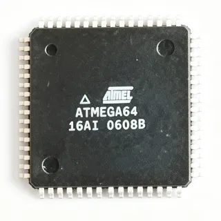
ATMEGA8535L-8AJ - 8KB AVR MCU, 8MHz, TQFP-44 | Microchip
部品番号: ATMEGA8535L-8AJ ✓ 生産中| 数量 | 単価 | 小計 |
|---|---|---|
| 1 | $4.2 | $4.20 |
| 10 | $3.78 | $37.80 |
| 100 | $3.36 | $336.00 |
| 500 | $3.02 | $1,510.00 |
| 1,000 | $2.7 | $2,700.00 |
ATMEGA8535L-8AJ 概要
An 8-bit microcontroller (MCU) is a single-chip computer that integrates a processor core, program memory, data memory, and peripherals on one die. In the embedded-systems hierarchy, an MCU sits above discrete logic and below application processors, providing self-contained control for sensors, actuators, and human-machine interfaces.
Key features of the ATMEGA8535L include the AVR advanced RISC architecture with 130 powerful instructions, most executing in a single clock cycle, and 32 general-purpose working registers. The core delivers up to 16 MIPS throughput at 16MHz, so at the 8MHz limit of this L-grade part it still reaches roughly 8 MIPS. Communication peripherals include a byte-oriented Two-wire Serial Interface (I2C/TWI), an SPI interface, and a programmable USART (UART), covering virtually all common embedded buses.
The peripheral set comprises three flexible Timer/Counters with compare and PWM modes, internal and external interrupt sources, a watchdog timer, and the 8-channel 10-bit analog-to-digital converter with internal reference options, plus 32 general-purpose I/O lines. In-System Self-Programming of the Flash with Read-While-Write support enables field firmware updates without a socketed device.
Typical applications include industrial control panels, battery-powered instruments (leveraging the 2.7V low-voltage operation and low-power idle/power-down modes), sensor data acquisition front ends using the 8-channel ADC, and motor control or lighting systems using the PWM timer outputs.
Design consideration: the 8MHz clock ceiling of this L-grade device is the trade-off for 2.7V operation; if your design runs at 5V and needs 16MHz, choose the ATMEGA8535-16A variants instead.
This page synthesizes verified distributor inventory data, drop-in alternatives, and practical design guidance not found in a single manufacturer datasheet.
ドロップイン代替品: ATMEGA8535L-8AJ — 同一パッケージでピン互換。PCBの作り直しが必要な異なるパッケージの部品は除外されています。
このシリーズのバリエーション
同一シリーズでドロップイン互換のモデル: ATMEGA8535L-8AJ (同一形状・フットプリント) — 相違点: Throughput, Package, RoHS Status, Core Architecture, Instructions.
クイック比較ツール — 並列比較する代替部品を選択:
ATMEGA8535-16AU
✅ ドロップイン✓ 在庫あり
$4.41 / 個
データシートを見る →ATMEGA8535-16AI
✅ ドロップイン ⚠️ 仕様未検証📋 参考代替品(カタログ未掲載)
ATMEGA8535L-8AI
✅ ドロップイン ⚠️ 仕様未検証📋 参考代替品(カタログ未掲載)
ATMEGA8515L-8AI
✅ ドロップイン✓ 在庫あり
$2.05 / 個
データシートを見る →ATMEGA8515L-8AUR
✅ ドロップイン✓ 在庫あり
$1.98 / 個
データシートを見る →ATMEGA8535L-8AJ 最大定格&電気的特性
| Core | 8-bit AVR RISC |
| Core Speed | 8 MHz (L-grade maximum) |
| Flash Program Memory | 8 KB (4K x 16) In-System Self-Programmable |
| SRAM | 512 bytes |
| EEPROM | 512 bytes |
| ADC | 8-channel, 10-bit |
| GPIO Count | 32 |
| Communication Interfaces | I2C (TWI), SPI, UART/USART |
| Timers | Three Timer/Counters with compare modes |
| Operating Voltage Range | 2.7 V to 5.5 V (L suffix) |
| 動作温度 | -40C to +85C (industrial, J suffix) |
| Instructions | 130 instructions, most single-cycle |
| パッケージ | 44-TQFP (10 x 10 mm) |
| 実装タイプ | Surface Mount |
| Throughput | Up to 16 MIPS at 16 MHz (family rating) |
| RoHS ステータス | Compliant |
ATMEGA8535L-8AJ ピン構成
| ピン 1 | PA0 (ADC0) — Port A bit 0 / ADC channel 0 |
| ピン 2 | PA1 (ADC1) — Port A bit 1 / ADC channel 1 |
| ピン 3 | PA2 (ADC2) — Port A bit 2 / ADC channel 2 |
| ピン 4 | PA3 (ADC3) — Port A bit 3 / ADC channel 3 |
| ピン 5 | PA4 (ADC4) — Port A bit 4 / ADC channel 4 |
| ピン 6 | PA5 (ADC5) — Port A bit 5 / ADC channel 5 |
| ピン 7 | PA6 (ADC6) — Port A bit 6 / ADC channel 6 |
| ピン 8 | PA7 (ADC7) — Port A bit 7 / ADC channel 7 |
| ピン 9 | PE0 (RXD/PDI) — Port E bit 0 / USART receive / programming data input |
| ピン 10 | PE1 (TXD/PDO) — Port E bit 1 / USART transmit / programming data output |
| ピン 11 | PB0 (XCK/T0) — Port B bit 0 / USART external clock / Timer0 external clock |
| ピン 12 | PB1 (T1) — Port B bit 1 / Timer1 external clock |
| ピン 13 | PB2 (AIN0/INT2) — Port B bit 2 / analog comparator input 0 / external interrupt 2 |
| ピン 14 | PB3 (AIN1/OC0) — Port B bit 3 / analog comparator input 1 / Timer0 output compare |
| ピン 15 | PB4 (SS) — Port B bit 4 / SPI slave select |
| ピン 16 | PB5 (MOSI) — Port B bit 5 / SPI master output |
| ピン 17 | PB6 (MISO) — Port B bit 6 / SPI master input |
| ピン 18 | PB7 (SCK/OC2) — Port B bit 7 / SPI clock / Timer2 output compare |
| ピン 19 | VCC — Digital supply voltage |
| ピン 20 | GND — Ground |
| ピン 21 | RESET — Reset input (active low) |
| ピン 22 | XTAL2 — Oscillator output |
| ピン 23 | XTAL1 — Oscillator input |
| ピン 24 | AVCC — ADC supply voltage |
| ピン 25 | AREF — ADC reference voltage |
| ピン 26 | GND — Ground |
| ピン 27 | PC0 (SCL) — Port C bit 0 / TWI clock |
| ピン 28 | PC1 (SDA) — Port C bit 1 / TWI data |
| ピン 29 | PC2 (TCK) — Port C bit 2 / JTAG test clock |
| ピン 30 | PC3 (TMS) — Port C bit 3 / JTAG test mode select |
| ピン 31 | PC4 (TDO) — Port C bit 4 / JTAG test data output |
| ピン 32 | PC5 (TDI) — Port C bit 5 / JTAG test data input |
| ピン 33 | PC6 (TOSC1) — Port C bit 6 / Timer oscillator input |
| ピン 34 | PC7 (TOSC2) — Port C bit 7 / Timer oscillator output |
| ピン 35 | PD0 — Port D bit 0 |
| ピン 36 | PD1 — Port D bit 1 |
| ピン 37 | PD2 (INT0) — Port D bit 2 / external interrupt 0 |
| ピン 38 | PD3 (INT1) — Port D bit 3 / external interrupt 1 |
| ピン 39 | PD4 (OC1B) — Port D bit 4 / Timer1 output compare B |
| ピン 40 | PD5 (OC1A) — Port D bit 5 / Timer1 output compare A |
| ピン 41 | PD6 (ICP1) — Port D bit 6 / Timer1 input capture |
| ピン 42 | PD7 — Port D bit 7 |
| ピン 43 | VCC — Digital supply voltage |
| ピン 44 | GND — Ground |
主な用途
ATMEGA8535L-8AJ の用途: 6 件s: Industrial Control Systems, Battery-Powered Instruments, Multi-Channel Analog Data Acquisition, PWM Motor and Lighting Control, Embedded Communication Bridges, Legacy AVR System Sustenance.
Industrial Control Systems
The ATMEGA8535L-8AJ fits industrial control panels and PLC-style I/O modules because it combines 32 GPIO lines, three Timer/Counters with compare modes, and both external and internal interrupt sources in one 44-TQFP device. Its industrial -40C to +85C temperature rating and I2C/SPI/USART set allow direct interfacing with relays, encoders, HMI displays, and Modbus-style UART links. The AVR core's single-cycle execution gives roughly 8 MIPS at 8MHz, sufficient for deterministic scan loops. Running from a 5V industrial rail provides noise margin, while the 2.7V floor permits low-voltage control electronics when needed.
おすすめ
Battery-Powered Instruments
The L-grade 2.7V to 5.5V operating range of the ATMEGA8535L-8AJ makes it well suited to battery-powered handheld meters and dataloggers. The AVR architecture offers low-power idle and power-down sleep modes, and the 512-byte EEPROM retains calibration constants across battery replacement without external NVRAM. An 8MHz clock ceiling keeps dynamic current low, and the integrated 10-bit ADC eliminates a separate converter IC, reducing BOM cost and quiescent drain. Designers typically clock from a watch crystal in sleep and the internal 8MHz RC during active measurement to balance precision against power.
おすすめ
Multi-Channel Analog Data Acquisition
With an 8-channel 10-bit ADC multiplexed onto PORTA and an internal reference option, the ATMEGA8535L-8AJ can digitize up to eight analog sensor inputs without external conversion hardware. Typical uses include temperature arrays, pressure monitoring, and voltage-scan front ends where 10-bit resolution (roughly 4.9 mV LSB at 5V reference) is adequate. Successive-approximation conversion supports free-running or single-shot modes under Timer/Counter or interrupt control, letting firmware synchronize sampling with process events. SPI then streams results to external memory or a host, while TWI interfaces digital sensors on the same bus.
おすすめ
PWM Motor and Lighting Control
Three Timer/Counters with compare modes generate multiple PWM channels directly from the ATMEGA8535L-8AJ, suiting DC motor speed control, servo driving, and LED dimming. Timer outputs on PORTB and PORTD (e.g., OC0/OC1A/OC1B pins) deliver hardware PWM independent of software jitter, while the ADC can close the loop by reading back current or position from PORTA sensor channels. At 8MHz, PWM resolution up to 10-bit remains practical; the 16MHz -16A grade doubles loop bandwidth for demanding servo applications. The USART supports DMX-style or host command links for setpoint control.
おすすめ
Embedded Communication Bridges
The ATMEGA8535L-8AJ integrates a byte-oriented Two-wire Serial Interface (I2C/TWI), an SPI port, and a full programmable USART, making it a natural protocol converter between legacy and modern buses. Examples include UART-to-I2C gateways for sensor networks, SPI-to-UART links between host controllers and peripherals, and TWI bus masters managing EEPROM, RTC, and display devices simultaneously. Hardware support for multi-master arbitration on the TWI bus and interrupt-driven USART buffering allows concurrent protocol handling. The 512-byte SRAM accommodates protocol framing buffers, while the 8KB Flash holds complete firmware stacks.
おすすめ
Legacy AVR System Sustenance
Many installed products - HVAC controllers, gate openers, gym equipment, and automotive test jigs - were designed around the ATmega8535 and now face shortages. The ATMEGA8535L-8AJ, with current distributor stock reported around 15,540 pieces (as of September 2026), lets engineers sustain those lines without PCB redesign: the 44-TQFP footprint and firmware compatibility are unchanged across the family. Field firmware updates are possible via In-System Self-Programming of the 8KB Flash with Read-While-Write. Stocking the 8MHz L-grade and the 16MHz -16A grade together covers both low-voltage and full-speed legacy variants.
おすすめ
おすすめ製品の概要
エンジニアリング参考データ: ATMEGA8535L-8AJ — 比較、設計ガイダンス、コンプライアンス情報。
選定ガイド
代替品との比較
| パラメータ | この製品 | ATMEGA8535-16AU | ATMEGA8535-16AI | ATMEGA8535L-8AI | ATMEGA8515L-8AI |
|---|---|---|---|---|---|
| Package | 44-TQFP (10x10 mm) | 44-TQFP - same footprint | 44-TQFP - same footprint | 44-TQFP - same footprint | 44-TQFP - same footprint |
| Brand | Microchip Technology | Microchip Technology | Microchip Technology | Microchip Technology | Microchip Technology |
| Core Speed | 8 MHz | 16 MHz | 16 MHz | 8 MHz | 8 MHz |
| Operating Voltage | 2.7 V to 5.5 V | 4.5 V to 5.5 V | 4.5 V to 5.5 V | 2.7 V to 5.5 V | 2.7 V to 5.5 V |
| Flash Memory | 8 KB | 8 KB | 8 KB | 8 KB | 8 KB |
| SRAM | 512 bytes | 512 bytes | 512 bytes | 512 bytes | 512 bytes |
| ADC | 8-channel 10-bit | 8-channel 10-bit | 8-channel 10-bit | 8-channel 10-bit | None (no ADC) |
| Operating Temperature | -40C to +85C | -40C to +85C | -40C to +85C | -40C to +85C | -40C to +85C |
主な差別化要因
- True low-voltage operation down to 2.7V (vs ATMEGA8535-16AU)
- Integrated 8-channel 10-bit ADC (vs ATMEGA8515L-8AI)
- Extended port count with PE0/PE1 (vs ATMEGA8-16AI)
設計ノート
Connect AVCC (pin 24) to VCC through a low-pass RC filter (e.g., 10 ohm series resistor with 100 nF to GND) even if ADC is unused - Microchip requires AVCC within 0.3V of VCC for correct operation. When using the ADC, add 100 nF from AREF (pin 25) to ground; use an external reference only if better than approximately 4.9 mV/LSB accuracy at 5V is required. Keep PE0/PE1 UART lines away from the ADC traces to minimize crosstalk into the 10-bit converter.
The 44-TQFP 10x10 mm footprint uses 0.8 mm pitch, which is hand-solderable and prototyping-friendly. Place 100 nF ceramic decoupling capacitors within 3 mm of both VCC (pins 19 and 43) and both GND pins, with one bulk 4.7-10 uF capacitor per supply rail. The center of the TQFP allows via escape to inner ground planes - flood the area under the package with ground and stitch it to the plane for lower impedance and better EMC performance.
Do not exceed the 8MHz limit of this L-grade part - the -8AJ suffix encodes the 8MHz ceiling, unlike the 16MHz ATMEGA8535-16A grades. Also note the L-grade part still works at 5V, so designs can run 8MHz at 5V safely. When migrating firmware from ATmega8515 to ATmega8535, remember the ADC and PE0/PE1 port additions; when migrating in the opposite direction, ADC-dependent code will fail silently since ATmega8515 has no converter. Verify fuse settings (SPIEN must remain enabled) to avoid locking out ISP access.
PC0-PC7 are open-drain when TWI is enabled; always fit external 4.7 kohm pull-up resistors on the SCL/SDA lines (PC0/PC1) at 100-400 kHz I2C operation. For SPI on PB4-PB7 keep traces short (under 10 cm) and route away from the XTAL oscillator loop. If a 32.768 kHz watch crystal is used on TOSC1/TOSC2 (PC6/PC7), keep the loop area minimal and ground-guard the traces to avoid startup failures.
コンプライアンス情報
RoHS compliant / lead-free per distributor listings (J suffix denotes green industrial package). REACH, halogen-free, and conflict-minerals declarations should be obtained from Microchip's official product page documentation.