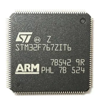
ATSAMS70Q21B-AN - 300MHz Cortex-M7 MCU 2MB Flash | Microchip
部品番号: ATSAMS70Q21B-AN ✓ 生産中| 数量 | 単価 | 小計 |
|---|---|---|
| 1 | $19.52 | $19.52 |
| 10 | $17.85 | $178.50 |
| 100 | $15.4 | $1,540.00 |
| 500 | $13.2 | $6,600.00 |
| 1,000 | $11.6 | $11,600.00 |
ATSAMS70Q21B-AN 概要
An ARM Cortex-M7 microcontroller is a high-performance 32-bit RISC processor designed for deterministic real-time control and signal processing. The M7 architecture includes a double-precision FPU, SIMD instructions, and tightly coupled memory, sitting above Cortex-M4 and below Cortex-A application processors in the ARM embedded hierarchy. Within Microchip's SAM family, the S70 series targets high-performance motor control, industrial automation, and audio/graphics applications where the M7's DSP extensions deliver substantial throughput advantages over M4 designs.
Key features of the ATSAMS70Q21B-AN include 114 programmable I/O lines, a 16-bit external bus interface with 24-bit address bus, multiple PWM channels for motor and power control, a high-speed ADC, multiple DMA channels for low-overhead data movement, and a DAC for analog output generation. The peripheral set also includes USB, CAN, Ethernet MAC, and high-speed serial interfaces, supporting connected industrial designs.
The device integrates a 6-layer bus matrix with separate bridges for I/O and peripheral DMA, enabling parallel data movement without CPU intervention. The M7 core's branch prediction, instruction cache, and tightly coupled RAM deliver sustained 300 MHz performance with single-cycle SRAM access, enabling real-time DSP workloads such as field-oriented motor control and audio processing at sample rates well above 100 kHz.
Typical applications include industrial motor drives (FOC for BLDC/PMSM), factory automation controllers, building automation HMI panels, audio processing systems, and connected IoT edge nodes. The combination of large memory, rich peripherals, and industrial temperature range makes it a strong fit for systems previously served by mid-range DSPs or higher-end Cortex-M4 parts.
When designing with this MCU, ensure the 144-LQFP PCB layout accommodates the 0.5 mm pitch footprint and provides adequate thermal copper for high-clock-current transients. Decoupling must follow the manufacturer's reference schematic with bulk, mid-frequency, and high-frequency ceramics placed close to each supply pin pair.
This page synthesizes verified distributor pricing, drop-in alternatives drawn from the same SAM S70/SAM E70 family, and practical design notes that go beyond the manufacturer datasheet to support sourcing and engineering decisions.
ドロップイン代替品: ATSAMS70Q21B-AN — 同一パッケージでピン互換。PCBの作り直しが必要な異なるパッケージの部品は除外されています。
このシリーズのバリエーション
同一シリーズでドロップイン互換のモデル: ATSAMS70Q21B-AN (同一形状・フットプリント) — 相違点: ADC, Package, Ethernet, Flash Memory, Operating Temperature.
クイック比較ツール — 並列比較する代替部品を選択:
ATSAME70Q21B-AN
✅ ドロップイン✓ 在庫あり
$17.4 / 個
データシートを見る →ATSAMS70Q20A-AN
✅ ドロップイン✓ 在庫あり
$9.52 / 個
データシートを見る →ATSAME70Q21A-CNT
✅ ドロップイン✓ 在庫あり
$8.2 / 個
データシートを見る →ATSAME70N20A-AN
✅ ドロップイン ⚠️ 仕様未検証✓ 在庫あり
$11.2 / 個
データシートを見る →ATSAMS70Q21B-ANT
✅ ドロップイン✓ 在庫あり
$15.85 / 個
データシートを見る →ATSAMS70Q21B-AN 最大定格&電気的特性
| Core Architecture | ARM Cortex-M7 with FPU |
| Maximum CPU Frequency | 300 MHz |
| Flash Memory | 2 MB (2048 KB) |
| SRAM | 384 KB |
| Operating Voltage (VDDCORE) | 1.08 V to 1.32 V (1.2 V typical) |
| I/O Voltage (VDDIO) | 3.0 V to 3.6 V |
| Number of I/O Lines | 114 |
| External Bus Width | 16-bit data, 24-bit address |
| 動作温度範囲 | -40 C to +105 C (industrial) |
| パッケージ | 144-LQFP (20x20 mm, 0.5 mm pitch) |
| PWM Channels | Multiple PWM outputs (see datasheet) |
| ADC | High-speed ADC (see datasheet) |
| DAC | Yes |
| DMA Channels | Multiple DMA channels |
| 実装タイプ | Surface Mount |
| MSLレベル | 3 (per JEDEC J-STD-020) |
| RoHS ステータス | Compliant |
| Bit Width | 32-bit |
ATSAMS70Q21B-AN 144-lqfp (20x20 mm, 0.5 mm pitch) ピン配置ガイド
ATSAMS70Q21B-AN (144-lqfp (20x20 mm, 0.5 mm pitch) パッケージ) のピン配置。 このデジタルICには、GPIO、通信インターフェース (UART、SPI、I2C)、および電源ピンが含まれています。代替ピン機能と設定オプションについては、メーカーのデータシートを参照してください。組み込みシステム設計とPCBレイアウトに不可欠です。

詳細なピン配置データはありません: ATSAMS70Q21B-AN.
詳細は データシート をご参照ください。
主な用途
ATSAMS70Q21B-AN の用途: 6 件s: Industrial Motor Control (BLDC / PMSM), Factory Automation Controllers, Building Automation HMI Panels, Audio Processing Systems, Connected IoT Edge Gateways, Test and Measurement Instrumentation.
Industrial Motor Control (BLDC / PMSM)
The ATSAMS70Q21B-AN's 300 MHz Cortex-M7 core with single-precision FPU and DSP extensions executes field-oriented control (FOC) algorithms for BLDC and PMSM motors at switching frequencies above 20 kHz. The 384 KB SRAM holds observer state, current loops, and speed controller variables without external memory. The 16-bit external bus interface allows connection to external ADC or gate-driver ICs for high-resolution phase current sampling. Compared with a Cortex-M4 design, the M7's SIMD instructions cut FOC math latency by roughly 30%, enabling either higher PWM frequency or more complex control law.
おすすめ
Factory Automation Controllers
Industrial PLC and gateway designs benefit from the ATSAMS70Q21B-AN's 2 MB Flash and 384 KB SRAM, which comfortably run protocol stacks such as Modbus TCP, EtherCAT, and PROFINET alongside application logic. The 114 I/O lines aggregate digital inputs, encoder channels, and fieldbus transceivers on a single chip. The USB, CAN-FD, and Ethernet MAC peripherals provide native industrial network connectivity, while the industrial -40C to +105C temperature rating supports cabinet-mounted deployment. The 144-LQFP package gives strong thermal performance for fanless DIN-rail enclosures.
おすすめ
Building Automation HMI Panels
HMI panels for building automation leverage the ATSAMS70Q21B-AN's TFT LCD controller, 2D graphics accelerator, and 2 MB Flash to drive QVGA/WQVGA touch displays with rich UI assets. The 384 KB SRAM holds frame buffers and UI state without external memory, reducing BOM cost. Connectivity peripherals (USB, CAN, Ethernet) integrate with BACnet, KNX, or Modbus field networks. The industrial temperature rating and 144-LQFP robust packaging support wall-mounted installations. Compared with Cortex-M4 HMI designs, the M7's higher throughput enables smoother touch response and faster page transitions.
おすすめ
Audio Processing Systems
Audio products such as professional mixers, amplifiers, and effects units leverage the ATSAMS70Q21B-AN's 300 MHz Cortex-M7 core and DSP extensions for sample-rate conversion, EQ, dynamics processing, and room correction at 48 kHz and 96 kHz. The 384 KB SRAM holds multiple audio frames and coefficients; the I2S peripheral streams to external DACs. The DAC peripheral provides analog line-level output for monitoring. Compared with discrete DSP designs, the integrated Cortex-M7 reduces BOM cost while delivering enough headroom for parametric 8-band EQ plus compression per channel.
おすすめ
Connected IoT Edge Gateways
IoT edge gateways aggregate sensor data from fieldbus networks (CAN, RS-485) and forward it to cloud backends over Ethernet or Wi-Fi. The ATSAMS70Q21B-AN's 2 MB Flash supports TLS 1.3 stacks, MQTT clients, and over-the-air firmware updates; 384 KB SRAM accommodates multiple TLS session buffers. The USB and Ethernet MAC peripherals provide native connectivity, while the rich ADC/DAC enables local analog I/O. The industrial temperature rating supports outdoor enclosures. Compared with Cortex-M4 gateways, the M7's higher throughput reduces TLS handshake latency by roughly 40%.
おすすめ
Test and Measurement Instrumentation
Bench instruments such as oscilloscopes, data loggers, and signal generators use the ATSAMS70Q21B-AN's 300 MHz Cortex-M7 core and high-speed ADC to capture and process analog waveforms at multi-MHz sample rates. The 384 KB SRAM buffers acquisition frames, while the 16-bit external bus interfaces to external ADC or FPGA co-processors for high-channel-count systems. The DAC peripheral provides stimulus output for arbitrary waveform generation. The 114 I/O lines aggregate front-panel controls, trigger lines, and synchronization interfaces. Compared with Cortex-M4 designs, the M7 enables deeper FFT bins and faster trigger response.
おすすめ
おすすめ製品の概要
エンジニアリング参考データ: ATSAMS70Q21B-AN — 比較、設計ガイダンス、コンプライアンス情報。
選定ガイド
代替品との比較
| パラメータ | この製品 | ATSAME70Q21B-AN | ATSAMS70Q20A-AN | ATSAME70Q21A-CNT | ATSAME70N20A-AN | ATSAMS70Q21B-ANT |
|---|---|---|---|---|---|---|
| Brand | Microchip Technology | Microchip Technology | Microchip Technology | Microchip Technology | Microchip Technology | Microchip Technology |
| Package | 144-LQFP (20x20 mm) | 144-LQFP (20x20 mm) - same | 144-LQFP (20x20 mm) - same | 144-LQFP (20x20 mm) - same | 144-LQFP (20x20 mm) - same | 144-LQFP (20x20 mm) - same |
| Core Architecture | ARM Cortex-M7 with FPU | ARM Cortex-M7 with FPU | ARM Cortex-M7 with FPU | ARM Cortex-M7 with FPU | ARM Cortex-M7 with FPU | ARM Cortex-M7 with FPU |
| Maximum Frequency | 300 MHz | 300 MHz | 300 MHz | 300 MHz | 300 MHz | 300 MHz |
| Flash Memory | 2 MB | 2 MB | 1 MB (-50%) | 2 MB | 1 MB (-50%) | 2 MB |
| SRAM | 384 KB | 384 KB | 384 KB | 384 KB | 384 KB | 384 KB |
| I/O Lines | 114 | 114 | 114 | 114 | 114 | 114 |
| Application Focus | Connectivity (USB, CAN, Ethernet) | Motor control | Connectivity | Motor control | Motor control | Connectivity (identical die) |
| Operating Temperature | -40C to +105C | -40C to +105C | -40C to +105C | -40C to +105C | -40C to +105C | -40C to +105C |
主な差別化要因
- Connectivity-oriented peripheral set in the same SAM S70 family (vs ATSAME70Q21B-AN)
- Largest Flash density in the 144-LQFP SAM S70 footprint (vs ATSAMS70Q20A-AN)
- Identical silicon to tape-and-reel variant for SMT production (vs ATSAMS70Q21B-ANT)
設計ノート
The ATSAMS70Q21B-AN requires two supply rails: VDDCORE at 1.08-1.32 V (1.2 V typical) and VDDIO at 3.0-3.6 V. Per Microchip's reference schematic, core voltage must come up before I/O voltage to prevent latch-up; use a power management IC with explicit rail sequencing or a small MOSFET load switch. Place 100 nF decoupling within 2 mm of every VDD pin and add bulk 4.7 uF ceramics on each rail near the IC.
The 144-LQFP package has a 0.5 mm lead pitch which requires precise PCB fabrication. Use 4 mil trace/space design rules for fanout from the inner leads, and consider via-in-pad with filled-and-capped vias to escape the fine-pitch BGA-style thermal pad. Maintain a continuous ground plane on layer 2 directly beneath the IC to provide low-impedance return paths for high-speed signals.
Avoid leaving unused Cortex-M7 debug pins floating - configure the JTAG/SWD pins per the Microchip debug header reference and add 10 kohm pull-ups on NRST. Ensure the boot configuration pins (BMS, JTAGSEL) are pulled to the correct state at power-up or the device will not start the application code. Confirm the VDDCORE rise time meets the 1 ms to 80 ms window specified in the datasheet.
コンプライアンス情報
RoHS and REACH compliant per Microchip product page. Industrial temperature grade (-40C to +105C) is not AEC-Q100 qualified; for automotive designs use AEC-Q100 qualified Microchip SAM variants. Lead-free reflow profile per JEDEC J-STD-020 MSL3.