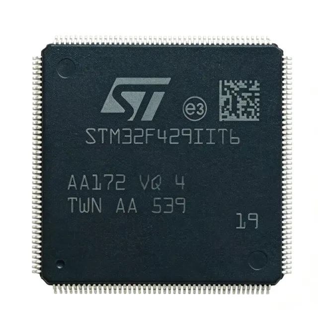
STM32F429IIT6 - 180MHz ARM Cortex-M4 MCU with 2MB Flash | STMicroelectronics
部品番号: STM32F429IIT6 ✓ 生産中| 数量 | 単価 | 小計 |
|---|---|---|
| 1 | $14.3182 | $14.32 |
| 10 | $10.3409 | $103.41 |
| 100 | $9.1477 | $914.77 |
| 500 | $8.75 | $4,375.00 |
| 1,000 | $8.3523 | $8,352.30 |
STM32F429IIT6 概要
A microcontroller (MCU) is a compact integrated circuit designed to govern a specific operation in an embedded system. It contains a processor core, memory, and programmable input/output peripherals. The STM32F429IIT6 belongs to the STM32F4 series, which is part of the broader STM32 family of 32-bit Flash microcontrollers based on the ARM Cortex-M processor. These MCUs are widely used in industrial control, consumer electronics, and Internet of Things (IoT) devices due to their balance of performance, power efficiency, and peripheral integration.
Key features of the STM32F429IIT6 include a rich set of peripherals: multiple 12-bit ADCs, DACs, timers, USARTs, SPIs, I2Cs, USB OTG, CAN, and an LCD-TFT controller. It also supports external memory interfaces (FSMC) for expanding memory beyond the on-chip resources. The device includes a cryptographic acceleration cell and a true random number generator, enhancing security for applications requiring data protection. With a comprehensive set of development tools and middleware from STMicroelectronics, the STM32F429IIT6 accelerates time-to-market for embedded designs.
Technically, the STM32F429IIT6 leverages the ARM Cortex-M4 core with DSP instructions and a single-precision FPU, enabling efficient execution of complex algorithms such as digital signal processing and motor control. The memory architecture includes an 8-KB instruction cache and a 4-KB data cache to optimize performance when accessing external memory. The device supports a wide range of clock sources, including internal RC oscillators, external crystals, and PLLs, allowing designers to balance performance and power consumption.
Typical applications include industrial automation, motor drives, medical devices, audio processing, and human-machine interfaces (HMI) with graphical displays. The integrated LCD-TFT controller simplifies the design of color displays, while the advanced timer peripherals provide precise PWM generation for motor control. The device's low-power modes, including Sleep, Stop, and Standby, enable battery-powered applications to extend operational life.
When designing with the STM32F429IIT6, ensure proper decoupling of the power supply pins with 100 nF capacitors placed close to each VDD pin. The VDDA analog supply should be filtered with a ferrite bead and a 1 uF capacitor to reduce noise for ADC accuracy. Additionally, the BOOT0 pin configuration must be set correctly to select the boot source, and the NRST pin should have an external pull-up resistor and a capacitor for reliable reset operation.
ドロップイン代替品: STM32F429IIT6 — 同一パッケージでピン互換。PCBの作り直しが必要な異なるパッケージの部品は除外されています。
このシリーズのバリエーション
同一シリーズでドロップイン互換のモデル: STM32F429IIT6 (同一形状・フットプリント) — 相違点: Package, Timers, Operating Temperature Range, ADC, Communication Interfaces.
クイック比較ツール — 並列比較する代替部品を選択:
STM32F429NIH6
✓ 在庫あり
$8.63 / 個
データシートを見る →STM32F407IIT6
📋 参考代替品(カタログ未掲載)
STM32F427IIT6
✓ 在庫あり
$11.2 / 個
データシートを見る →STM32F429IGT6
✓ 在庫あり
価格はお問い合わせください
データシートを見る →STM32F429IIT6 最大定格&電気的特性
| Core | ARM Cortex-M4 with FPU |
| 最大クロック周波数 | 180 MHz |
| Flash Memory | 2 MB |
| SRAM | 256 KB |
| Supply Voltage Range | 1.8 V to 3.6 V |
| パッケージ | LQFP176 |
| ピン数 | 176 |
| 動作温度範囲 | -40C to +85C |
| ADC Resolution | 12-bit |
| Number of ADC Channels | 24 |
| DAC Resolution | 12-bit |
| Number of Timers | 14 |
| Number of USARTs | 8 |
| Number of SPIs | 6 |
| Number of I2Cs | 4 |
| USB OTG | 2 (FS and HS) |
| CAN | 2 |
| LCD-TFT Controller | Yes |
| External Memory Interface | FSMC |
| Cryptographic Acceleration | Yes |
| RoHS ステータス | Compliant |
STM32F429IIT6 ピン構成
| ピン 1 | PE2 — GPIO / FSMC_A23 |
| ピン 2 | PE3 — GPIO / FSMC_A19 |
| ピン 3 | PE4 — GPIO / FSMC_A20 |
| ピン 4 | PE5 — GPIO / FSMC_A21 |
| ピン 5 | PE6 — GPIO / FSMC_A22 |
| ピン 6 | VBAT — Battery backup supply |
| ピン 7 | PC13 — GPIO / RTC_AF1 |
| ピン 8 | PC14 — GPIO / OSC32_IN |
| ピン 9 | PC15 — GPIO / OSC32_OUT |
| ピン 10 | PF0 — GPIO / FSMC_A0 |
| ピン 11 | PF1 — GPIO / FSMC_A1 |
| ピン 12 | PF2 — GPIO / FSMC_A2 |
| ピン 13 | PF3 — GPIO / FSMC_A3 |
| ピン 14 | PF4 — GPIO / FSMC_A4 |
| ピン 15 | PF5 — GPIO / FSMC_A5 |
| ピン 16 | VSS — Ground |
| ピン 17 | VDD — Power supply |
| ピン 18 | PF6 — GPIO / FSMC_NREG |
| ピン 19 | PF7 — GPIO / FSMC_NREG |
| ピン 20 | PF8 — GPIO / FSMC_NREG |
| ピン 21 | PF9 — GPIO / FSMC_NREG |
| ピン 22 | PF10 — GPIO / FSMC_NREG |
| ピン 23 | PF11 — GPIO / FSMC_NREG |
| ピン 24 | PF12 — GPIO / FSMC_NREG |
| ピン 25 | PF13 — GPIO / FSMC_NREG |
| ピン 26 | PF14 — GPIO / FSMC_NREG |
| ピン 27 | PF15 — GPIO / FSMC_NREG |
| ピン 28 | VSS — Ground |
| ピン 29 | VDD — Power supply |
| ピン 30 | PG0 — GPIO / FSMC_A10 |
| ピン 31 | PG1 — GPIO / FSMC_A11 |
| ピン 32 | PG2 — GPIO / FSMC_A12 |
| ピン 33 | PG3 — GPIO / FSMC_A13 |
| ピン 34 | PG4 — GPIO / FSMC_A14 |
| ピン 35 | PG5 — GPIO / FSMC_A15 |
| ピン 36 | PG6 — GPIO / FSMC_NE1 |
| ピン 37 | PG7 — GPIO / FSMC_NE2 |
| ピン 38 | PG8 — GPIO / FSMC_NE3 |
| ピン 39 | PG9 — GPIO / FSMC_NE4 |
| ピン 40 | PG10 — GPIO / FSMC_NE5 |
| ピン 41 | PG11 — GPIO / FSMC_NE6 |
| ピン 42 | PG12 — GPIO / FSMC_NE7 |
| ピン 43 | PG13 — GPIO / FSMC_NE8 |
| ピン 44 | PG14 — GPIO / FSMC_NE9 |
| ピン 45 | PG15 — GPIO / FSMC_NE10 |
| ピン 46 | VSS — Ground |
| ピン 47 | VDD — Power supply |
| ピン 48 | PH0 — GPIO / OSC_IN |
| ピン 49 | PH1 — GPIO / OSC_OUT |
| ピン 50 | PH2 — GPIO / FSMC_SDCKE0 |
| ピン 51 | PH3 — GPIO / FSMC_SDNE0 |
| ピン 52 | PH4 — GPIO / FSMC_SDNE1 |
| ピン 53 | PH5 — GPIO / FSMC_SDNE2 |
| ピン 54 | PH6 — GPIO / FSMC_SDNE3 |
| ピン 55 | PH7 — GPIO / FSMC_SDNE4 |
| ピン 56 | PH8 — GPIO / FSMC_SDNE5 |
| ピン 57 | PH9 — GPIO / FSMC_SDNE6 |
| ピン 58 | PH10 — GPIO / FSMC_SDNE7 |
| ピン 59 | PH11 — GPIO / FSMC_SDNE8 |
| ピン 60 | PH12 — GPIO / FSMC_SDNE9 |
| ピン 61 | PH13 — GPIO / FSMC_SDNE10 |
| ピン 62 | PH14 — GPIO / FSMC_SDNE11 |
| ピン 63 | PH15 — GPIO / FSMC_SDNE12 |
| ピン 64 | VSS — Ground |
| ピン 65 | VDD — Power supply |
| ピン 66 | PI0 — GPIO / FSMC_D0 |
| ピン 67 | PI1 — GPIO / FSMC_D1 |
| ピン 68 | PI2 — GPIO / FSMC_D2 |
| ピン 69 | PI3 — GPIO / FSMC_D3 |
| ピン 70 | PI4 — GPIO / FSMC_D4 |
| ピン 71 | PI5 — GPIO / FSMC_D5 |
| ピン 72 | PI6 — GPIO / FSMC_D6 |
| ピン 73 | PI7 — GPIO / FSMC_D7 |
| ピン 74 | PI8 — GPIO / FSMC_D8 |
| ピン 75 | PI9 — GPIO / FSMC_D9 |
| ピン 76 | PI10 — GPIO / FSMC_D10 |
| ピン 77 | PI11 — GPIO / FSMC_D11 |
| ピン 78 | PI12 — GPIO / FSMC_D12 |
| ピン 79 | PI13 — GPIO / FSMC_D13 |
| ピン 80 | PI14 — GPIO / FSMC_D14 |
| ピン 81 | PI15 — GPIO / FSMC_D15 |
| ピン 82 | VSS — Ground |
| ピン 83 | VDD — Power supply |
| ピン 84 | PA0 — GPIO / ADC_IN0 / TIM2_CH1 |
| ピン 85 | PA1 — GPIO / ADC_IN1 / TIM2_CH2 |
| ピン 86 | PA2 — GPIO / ADC_IN2 / TIM2_CH3 |
| ピン 87 | PA3 — GPIO / ADC_IN3 / TIM2_CH4 |
| ピン 88 | PA4 — GPIO / ADC_IN4 / SPI1_NSS |
| ピン 89 | PA5 — GPIO / ADC_IN5 / SPI1_SCK |
| ピン 90 | PA6 — GPIO / ADC_IN6 / SPI1_MISO |
| ピン 91 | PA7 — GPIO / ADC_IN7 / SPI1_MOSI |
| ピン 92 | PA8 — GPIO / TIM1_CH1 |
| ピン 93 | PA9 — GPIO / USART1_TX |
| ピン 94 | PA10 — GPIO / USART1_RX |
| ピン 95 | PA11 — GPIO / USB_OTG_FS_DM |
| ピン 96 | PA12 — GPIO / USB_OTG_FS_DP |
| ピン 97 | PA13 — GPIO / SWDIO |
| ピン 98 | PA14 — GPIO / SWCLK |
| ピン 99 | PA15 — GPIO / JTDI |
| ピン 100 | VSS — Ground |
| ピン 101 | VDD — Power supply |
| ピン 102 | PB0 — GPIO / ADC_IN8 / TIM3_CH3 |
| ピン 103 | PB1 — GPIO / ADC_IN9 / TIM3_CH4 |
| ピン 104 | PB2 — GPIO / BOOT1 |
| ピン 105 | PB3 — GPIO / JTDO |
| ピン 106 | PB4 — GPIO / NJTRST |
| ピン 107 | PB5 — GPIO / I2C1_SMBA |
| ピン 108 | PB6 — GPIO / I2C1_SCL |
| ピン 109 | PB7 — GPIO / I2C1_SDA |
| ピン 110 | PB8 — GPIO / I2C1_SCL |
| ピン 111 | PB9 — GPIO / I2C1_SDA |
| ピン 112 | PB10 — GPIO / I2C2_SCL |
| ピン 113 | PB11 — GPIO / I2C2_SDA |
| ピン 114 | PB12 — GPIO / SPI2_NSS |
| ピン 115 | PB13 — GPIO / SPI2_SCK |
| ピン 116 | PB14 — GPIO / SPI2_MISO |
| ピン 117 | PB15 — GPIO / SPI2_MOSI |
| ピン 118 | VSS — Ground |
| ピン 119 | VDD — Power supply |
| ピン 120 | PC0 — GPIO / ADC_IN10 |
| ピン 121 | PC1 — GPIO / ADC_IN11 |
| ピン 122 | PC2 — GPIO / ADC_IN12 |
| ピン 123 | PC3 — GPIO / ADC_IN13 |
| ピン 124 | PC4 — GPIO / ADC_IN14 |
| ピン 125 | PC5 — GPIO / ADC_IN15 |
| ピン 126 | PC6 — GPIO / TIM3_CH1 |
| ピン 127 | PC7 — GPIO / TIM3_CH2 |
| ピン 128 | PC8 — GPIO / TIM3_CH3 |
| ピン 129 | PC9 — GPIO / TIM3_CH4 |
| ピン 130 | PC10 — GPIO / USART3_TX |
| ピン 131 | PC11 — GPIO / USART3_RX |
| ピン 132 | PC12 — GPIO / USART3_CK |
| ピン 133 | PC13 — GPIO / RTC_AF1 |
| ピン 134 | PC14 — GPIO / OSC32_IN |
| ピン 135 | PC15 — GPIO / OSC32_OUT |
| ピン 136 | VSS — Ground |
| ピン 137 | VDD — Power supply |
| ピン 138 | PD0 — GPIO / FSMC_D2 |
| ピン 139 | PD1 — GPIO / FSMC_D3 |
| ピン 140 | PD2 — GPIO / FSMC_D4 |
| ピン 141 | PD3 — GPIO / FSMC_D5 |
| ピン 142 | PD4 — GPIO / FSMC_D6 |
| ピン 143 | PD5 — GPIO / FSMC_D7 |
| ピン 144 | PD6 — GPIO / FSMC_D8 |
| ピン 145 | PD7 — GPIO / FSMC_D9 |
| ピン 146 | PD8 — GPIO / FSMC_D10 |
| ピン 147 | PD9 — GPIO / FSMC_D11 |
| ピン 148 | PD10 — GPIO / FSMC_D12 |
| ピン 149 | PD11 — GPIO / FSMC_D13 |
| ピン 150 | PD12 — GPIO / FSMC_D14 |
| ピン 151 | PD13 — GPIO / FSMC_D15 |
| ピン 152 | PD14 — GPIO / FSMC_D0 |
| ピン 153 | PD15 — GPIO / FSMC_D1 |
| ピン 154 | VSS — Ground |
| ピン 155 | VDD — Power supply |
| ピン 156 | PE0 — GPIO / TIM4_ETR |
| ピン 157 | PE1 — GPIO / TIM4_CH1 |
| ピン 158 | PE2 — GPIO / FSMC_A23 |
| ピン 159 | PE3 — GPIO / FSMC_A19 |
| ピン 160 | PE4 — GPIO / FSMC_A20 |
| ピン 161 | PE5 — GPIO / FSMC_A21 |
| ピン 162 | PE6 — GPIO / FSMC_A22 |
| ピン 163 | PE7 — GPIO / TIM1_ETR |
| ピン 164 | PE8 — GPIO / TIM1_CH1N |
| ピン 165 | PE9 — GPIO / TIM1_CH1 |
| ピン 166 | PE10 — GPIO / TIM1_CH2N |
| ピン 167 | PE11 — GPIO / TIM1_CH2 |
| ピン 168 | PE12 — GPIO / TIM1_CH3N |
| ピン 169 | PE13 — GPIO / TIM1_CH3 |
| ピン 170 | PE14 — GPIO / TIM1_CH4 |
| ピン 171 | PE15 — GPIO / TIM1_CH4N |
| ピン 172 | VSS — Ground |
| ピン 173 | VDD — Power supply |
| ピン 174 | NRST — Reset (active low) |
| ピン 175 | PC14 — GPIO / OSC32_IN |
| ピン 176 | PC15 — GPIO / OSC32_OUT |
主な用途
STM32F429IIT6 の用途: 6 件s: Industrial Automation, Motor Control, Medical Devices, Audio Processing, Human-Machine Interface (HMI), IoT Gateway.
Industrial Automation
The STM32F429IIT6 is ideal for industrial automation due to its high processing power, extensive peripheral set, and robust communication interfaces. It can handle complex control algorithms, real-time data acquisition, and multi-protocol communication (Ethernet, CAN, USB) in PLCs, motor drives, and robotic controllers. The 180 MHz Cortex-M4 core with FPU accelerates mathematical computations, while the multiple timers and ADCs enable precise PWM generation and analog signal processing. The device's industrial temperature range (-40C to +85C) ensures reliable operation in factory environments. Additionally, the FSMC interface allows connection to external memory for data logging, and the LCD-TFT controller supports local HMI displays for operator interaction.
おすすめ
Motor Control
The STM32F429IIT6 excels in motor control applications, such as field-oriented control (FOC) of brushless DC (BLDC) motors and permanent magnet synchronous motors (PMSM). Its advanced timers generate complementary PWM signals with dead-time insertion, while the high-speed ADCs sample phase currents simultaneously. The Cortex-M4 core with FPU executes complex control algorithms efficiently, enabling smooth and efficient motor operation. The device supports various communication interfaces (CAN, UART, SPI) for connecting to motor drives and host controllers. With its rich peripheral set and high performance, the STM32F429IIT6 is a cost-effective solution for industrial and automotive motor control systems.
おすすめ
Medical Devices
The STM32F429IIT6 is suitable for medical devices such as patient monitors, infusion pumps, and diagnostic equipment. Its high processing power enables real-time signal processing for ECG, EEG, and other biosignals. The multiple ADCs and DACs allow precise analog interfacing with sensors and actuators. The device's low-power modes help extend battery life in portable medical devices. The cryptographic acceleration cell and true random number generator enhance data security, which is critical for patient data protection. The LCD-TFT controller supports graphical user interfaces for displaying vital signs and device status. The industrial temperature range ensures reliable operation in clinical environments.
おすすめ
Audio Processing
The STM32F429IIT6 is well-suited for audio processing applications, including audio effects processors, mixers, and voice recognition systems. The Cortex-M4 core with FPU and DSP instructions accelerates audio algorithms such as filtering, FFT, and echo cancellation. The device's multiple I2S interfaces allow connection to audio codecs and digital microphones. The high-speed USB OTG enables streaming audio to and from a host. The large Flash memory (2 MB) can store audio samples and processing code. The LCD-TFT controller can display audio waveforms and user interfaces. With its high performance and rich audio peripherals, the STM32F429IIT6 is a powerful platform for professional and consumer audio products.
おすすめ
Human-Machine Interface (HMI)
The STM32F429IIT6 is an excellent choice for HMI applications, such as industrial control panels, home automation touchscreens, and point-of-sale terminals. Its integrated LCD-TFT controller supports up to XGA resolution with multiple color depths, enabling rich graphical user interfaces. The device's high processing power ensures smooth animation and responsive touch input. The external memory interface (FSMC) allows connection to external SDRAM or NOR Flash for larger frame buffers and graphics assets. The multiple communication interfaces (UART, SPI, I2C, USB) enable connection to touch controllers, sensors, and network modules. The device's low-power modes help reduce energy consumption in always-on displays.
おすすめ
IoT Gateway
The STM32F429IIT6 can serve as an IoT gateway, aggregating data from various sensors and devices and forwarding it to the cloud. Its multiple communication interfaces (Ethernet, USB, CAN, UART, SPI, I2C) allow connection to a wide range of sensors and actuators. The high processing power enables protocol conversion and data preprocessing. The cryptographic acceleration cell and true random number generator provide secure communication and data encryption. The device's low-power modes are beneficial for battery-powered gateways. The large Flash memory can store firmware updates and data logs. With its rich connectivity and security features, the STM32F429IIT6 is a robust platform for IoT edge devices.
おすすめ
おすすめ製品の概要
エンジニアリング参考データ: STM32F429IIT6 — 比較、設計ガイダンス、コンプライアンス情報。
選定ガイド
代替品との比較
| パラメータ | この製品 | STM32F429IIT6 | STM32F407IIT6 | STM32F427IIT6 | STM32F429IGT6 |
|---|---|---|---|---|---|
| Package | LQFP176 | LQFP176 | LQFP176 | LQFP176 | LQFP176 |
| Brand | STMicroelectronics | STMicroelectronics | STMicroelectronics | STMicroelectronics | STMicroelectronics |
| Maximum Clock Frequency | 180 MHz | 180 MHz | 168 MHz | 180 MHz | 180 MHz |
| Flash Memory | 2 MB | 2 MB | 1 MB | 2 MB | 1 MB |
| SRAM | 256 KB | 256 KB | 192 KB | 256 KB | 256 KB |
| LCD-TFT Controller | Yes | Yes | No | Yes | Yes |
| Cryptographic Acceleration | Yes | Yes | No | No | Yes |
| Number of Pins | 176 | 176 | 176 | 176 | 176 |
主な差別化要因
- Higher maximum clock frequency (180 MHz) compared to STM32F407IIT6 (168 MHz) (vs STM32F407IIT6)
- Integrated LCD-TFT controller (vs STM32F407IIT6)
- Cryptographic acceleration cell (vs STM32F427IIT6)
設計ノート
The STM32F429IIT6 requires a stable power supply. Decouple each VDD pin with a 100 nF ceramic capacitor placed as close to the pin as possible. Additionally, use a 4.7 uF capacitor on the VDDA pin and a ferrite bead to filter high-frequency noise. The VBAT pin should be connected to a backup battery or tied to VDD through a diode to maintain RTC operation when main power is off.
For optimal ADC performance, ensure the analog supply (VDDA) and reference voltage (VREF+) are clean and well-filtered. Use a star-ground topology to separate analog and digital grounds, and place the analog components away from high-speed digital traces. The LQFP176 package has an exposed pad (EP) that should be soldered to the PCB ground plane for improved thermal performance and mechanical stability.
When using the FSMC interface to connect external memory, ensure that the timing parameters are correctly configured to match the memory device. Incorrect timing can lead to data corruption. Also, be aware of the BOOT0 and BOOT1 pins: BOOT0 must be pulled low for normal boot from Flash, and BOOT1 is used to select the boot mode. Misconfiguration can prevent the device from starting correctly.
コンプライアンス情報
RoHS compliant per STMicroelectronics product page. Not AEC-Q100 qualified; for automotive, consider STM32F429IIT6Q or other automotive-grade variants.







