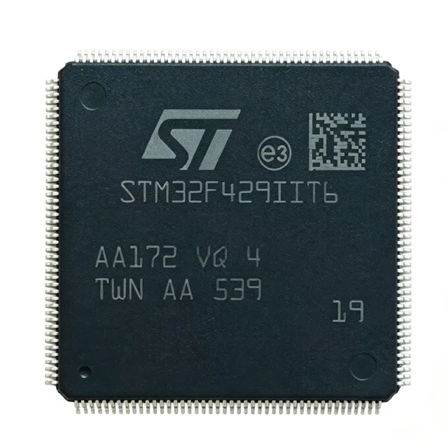
STM32F429IIT6 - 180MHz ARM Cortex-M4 MCU with 2MB Flash | STMicroelectronics
MPN: STM32F429IIT6 ✓ Active| Qty | Unit Price | Extended |
|---|---|---|
| 1 | $14.3182 | $14.32 |
| 10 | $10.3409 | $103.41 |
| 100 | $9.1477 | $914.77 |
| 500 | $8.75 | $4,375.00 |
| 1,000 | $8.3523 | $8,352.30 |
STM32F429IIT6 Overview
A microcontroller (MCU) is a compact integrated circuit designed to govern a specific operation in an embedded system. It contains a processor core, memory, and programmable input/output peripherals. The STM32F429IIT6 belongs to the STM32F4 series, which is part of the broader STM32 family of 32-bit Flash microcontrollers based on the ARM Cortex-M processor. These MCUs are widely used in industrial control, consumer electronics, and Internet of Things (IoT) devices due to their balance of performance, power efficiency, and peripheral integration.
Key features of the STM32F429IIT6 include a rich set of peripherals: multiple 12-bit ADCs, DACs, timers, USARTs, SPIs, I2Cs, USB OTG, CAN, and an LCD-TFT controller. It also supports external memory interfaces (FSMC) for expanding memory beyond the on-chip resources. The device includes a cryptographic acceleration cell and a true random number generator, enhancing security for applications requiring data protection. With a comprehensive set of development tools and middleware from STMicroelectronics, the STM32F429IIT6 accelerates time-to-market for embedded designs.
Technically, the STM32F429IIT6 leverages the ARM Cortex-M4 core with DSP instructions and a single-precision FPU, enabling efficient execution of complex algorithms such as digital signal processing and motor control. The memory architecture includes an 8-KB instruction cache and a 4-KB data cache to optimize performance when accessing external memory. The device supports a wide range of clock sources, including internal RC oscillators, external crystals, and PLLs, allowing designers to balance performance and power consumption.
Typical applications include industrial automation, motor drives, medical devices, audio processing, and human-machine interfaces (HMI) with graphical displays. The integrated LCD-TFT controller simplifies the design of color displays, while the advanced timer peripherals provide precise PWM generation for motor control. The device's low-power modes, including Sleep, Stop, and Standby, enable battery-powered applications to extend operational life.
When designing with the STM32F429IIT6, ensure proper decoupling of the power supply pins with 100 nF capacitors placed close to each VDD pin. The VDDA analog supply should be filtered with a ferrite bead and a 1 uF capacitor to reduce noise for ADC accuracy. Additionally, the BOOT0 pin configuration must be set correctly to select the boot source, and the NRST pin should have an external pull-up resistor and a capacitor for reliable reset operation.
Drop-in alternatives for STM32F429IIT6 — same package, pin-to-pin compatible. Different-package parts requiring PCB rework are excluded.
Variants in this series
Same-series models that are drop-in compatible with STM32F429IIT6 (same form factor and footprint) — differing in Package, Timers, Operating Temperature Range, ADC, Communication Interfaces.
Quick Comparison Tool — Select alternative parts for side-by-side comparison:
STM32F429NIH6
✓ In Stock
$8.63 / Unit
View Datasheet →STM32F407IIT6
📋 Reference alternative (not in catalog)
STM32F427IIT6
✓ In Stock
$11.2 / Unit
View Datasheet →STM32F429IGT6
✓ In Stock
Contact for price
View Datasheet →STM32F429IIT6 Maximum Ratings & Electrical Characteristics
| Core | ARM Cortex-M4 with FPU |
| Maximum Clock Frequency | 180 MHz |
| Flash Memory | 2 MB |
| SRAM | 256 KB |
| Supply Voltage Range | 1.8 V to 3.6 V |
| Package | LQFP176 |
| Number of Pins | 176 |
| Operating Temperature Range | -40C to +85C |
| ADC Resolution | 12-bit |
| Number of ADC Channels | 24 |
| DAC Resolution | 12-bit |
| Number of Timers | 14 |
| Number of USARTs | 8 |
| Number of SPIs | 6 |
| Number of I2Cs | 4 |
| USB OTG | 2 (FS and HS) |
| CAN | 2 |
| LCD-TFT Controller | Yes |
| External Memory Interface | FSMC |
| Cryptographic Acceleration | Yes |
| RoHS Status | Compliant |
STM32F429IIT6 Pin Configuration
| Pin 1 | PE2 — GPIO / FSMC_A23 |
| Pin 2 | PE3 — GPIO / FSMC_A19 |
| Pin 3 | PE4 — GPIO / FSMC_A20 |
| Pin 4 | PE5 — GPIO / FSMC_A21 |
| Pin 5 | PE6 — GPIO / FSMC_A22 |
| Pin 6 | VBAT — Battery backup supply |
| Pin 7 | PC13 — GPIO / RTC_AF1 |
| Pin 8 | PC14 — GPIO / OSC32_IN |
| Pin 9 | PC15 — GPIO / OSC32_OUT |
| Pin 10 | PF0 — GPIO / FSMC_A0 |
| Pin 11 | PF1 — GPIO / FSMC_A1 |
| Pin 12 | PF2 — GPIO / FSMC_A2 |
| Pin 13 | PF3 — GPIO / FSMC_A3 |
| Pin 14 | PF4 — GPIO / FSMC_A4 |
| Pin 15 | PF5 — GPIO / FSMC_A5 |
| Pin 16 | VSS — Ground |
| Pin 17 | VDD — Power supply |
| Pin 18 | PF6 — GPIO / FSMC_NREG |
| Pin 19 | PF7 — GPIO / FSMC_NREG |
| Pin 20 | PF8 — GPIO / FSMC_NREG |
| Pin 21 | PF9 — GPIO / FSMC_NREG |
| Pin 22 | PF10 — GPIO / FSMC_NREG |
| Pin 23 | PF11 — GPIO / FSMC_NREG |
| Pin 24 | PF12 — GPIO / FSMC_NREG |
| Pin 25 | PF13 — GPIO / FSMC_NREG |
| Pin 26 | PF14 — GPIO / FSMC_NREG |
| Pin 27 | PF15 — GPIO / FSMC_NREG |
| Pin 28 | VSS — Ground |
| Pin 29 | VDD — Power supply |
| Pin 30 | PG0 — GPIO / FSMC_A10 |
| Pin 31 | PG1 — GPIO / FSMC_A11 |
| Pin 32 | PG2 — GPIO / FSMC_A12 |
| Pin 33 | PG3 — GPIO / FSMC_A13 |
| Pin 34 | PG4 — GPIO / FSMC_A14 |
| Pin 35 | PG5 — GPIO / FSMC_A15 |
| Pin 36 | PG6 — GPIO / FSMC_NE1 |
| Pin 37 | PG7 — GPIO / FSMC_NE2 |
| Pin 38 | PG8 — GPIO / FSMC_NE3 |
| Pin 39 | PG9 — GPIO / FSMC_NE4 |
| Pin 40 | PG10 — GPIO / FSMC_NE5 |
| Pin 41 | PG11 — GPIO / FSMC_NE6 |
| Pin 42 | PG12 — GPIO / FSMC_NE7 |
| Pin 43 | PG13 — GPIO / FSMC_NE8 |
| Pin 44 | PG14 — GPIO / FSMC_NE9 |
| Pin 45 | PG15 — GPIO / FSMC_NE10 |
| Pin 46 | VSS — Ground |
| Pin 47 | VDD — Power supply |
| Pin 48 | PH0 — GPIO / OSC_IN |
| Pin 49 | PH1 — GPIO / OSC_OUT |
| Pin 50 | PH2 — GPIO / FSMC_SDCKE0 |
| Pin 51 | PH3 — GPIO / FSMC_SDNE0 |
| Pin 52 | PH4 — GPIO / FSMC_SDNE1 |
| Pin 53 | PH5 — GPIO / FSMC_SDNE2 |
| Pin 54 | PH6 — GPIO / FSMC_SDNE3 |
| Pin 55 | PH7 — GPIO / FSMC_SDNE4 |
| Pin 56 | PH8 — GPIO / FSMC_SDNE5 |
| Pin 57 | PH9 — GPIO / FSMC_SDNE6 |
| Pin 58 | PH10 — GPIO / FSMC_SDNE7 |
| Pin 59 | PH11 — GPIO / FSMC_SDNE8 |
| Pin 60 | PH12 — GPIO / FSMC_SDNE9 |
| Pin 61 | PH13 — GPIO / FSMC_SDNE10 |
| Pin 62 | PH14 — GPIO / FSMC_SDNE11 |
| Pin 63 | PH15 — GPIO / FSMC_SDNE12 |
| Pin 64 | VSS — Ground |
| Pin 65 | VDD — Power supply |
| Pin 66 | PI0 — GPIO / FSMC_D0 |
| Pin 67 | PI1 — GPIO / FSMC_D1 |
| Pin 68 | PI2 — GPIO / FSMC_D2 |
| Pin 69 | PI3 — GPIO / FSMC_D3 |
| Pin 70 | PI4 — GPIO / FSMC_D4 |
| Pin 71 | PI5 — GPIO / FSMC_D5 |
| Pin 72 | PI6 — GPIO / FSMC_D6 |
| Pin 73 | PI7 — GPIO / FSMC_D7 |
| Pin 74 | PI8 — GPIO / FSMC_D8 |
| Pin 75 | PI9 — GPIO / FSMC_D9 |
| Pin 76 | PI10 — GPIO / FSMC_D10 |
| Pin 77 | PI11 — GPIO / FSMC_D11 |
| Pin 78 | PI12 — GPIO / FSMC_D12 |
| Pin 79 | PI13 — GPIO / FSMC_D13 |
| Pin 80 | PI14 — GPIO / FSMC_D14 |
| Pin 81 | PI15 — GPIO / FSMC_D15 |
| Pin 82 | VSS — Ground |
| Pin 83 | VDD — Power supply |
| Pin 84 | PA0 — GPIO / ADC_IN0 / TIM2_CH1 |
| Pin 85 | PA1 — GPIO / ADC_IN1 / TIM2_CH2 |
| Pin 86 | PA2 — GPIO / ADC_IN2 / TIM2_CH3 |
| Pin 87 | PA3 — GPIO / ADC_IN3 / TIM2_CH4 |
| Pin 88 | PA4 — GPIO / ADC_IN4 / SPI1_NSS |
| Pin 89 | PA5 — GPIO / ADC_IN5 / SPI1_SCK |
| Pin 90 | PA6 — GPIO / ADC_IN6 / SPI1_MISO |
| Pin 91 | PA7 — GPIO / ADC_IN7 / SPI1_MOSI |
| Pin 92 | PA8 — GPIO / TIM1_CH1 |
| Pin 93 | PA9 — GPIO / USART1_TX |
| Pin 94 | PA10 — GPIO / USART1_RX |
| Pin 95 | PA11 — GPIO / USB_OTG_FS_DM |
| Pin 96 | PA12 — GPIO / USB_OTG_FS_DP |
| Pin 97 | PA13 — GPIO / SWDIO |
| Pin 98 | PA14 — GPIO / SWCLK |
| Pin 99 | PA15 — GPIO / JTDI |
| Pin 100 | VSS — Ground |
| Pin 101 | VDD — Power supply |
| Pin 102 | PB0 — GPIO / ADC_IN8 / TIM3_CH3 |
| Pin 103 | PB1 — GPIO / ADC_IN9 / TIM3_CH4 |
| Pin 104 | PB2 — GPIO / BOOT1 |
| Pin 105 | PB3 — GPIO / JTDO |
| Pin 106 | PB4 — GPIO / NJTRST |
| Pin 107 | PB5 — GPIO / I2C1_SMBA |
| Pin 108 | PB6 — GPIO / I2C1_SCL |
| Pin 109 | PB7 — GPIO / I2C1_SDA |
| Pin 110 | PB8 — GPIO / I2C1_SCL |
| Pin 111 | PB9 — GPIO / I2C1_SDA |
| Pin 112 | PB10 — GPIO / I2C2_SCL |
| Pin 113 | PB11 — GPIO / I2C2_SDA |
| Pin 114 | PB12 — GPIO / SPI2_NSS |
| Pin 115 | PB13 — GPIO / SPI2_SCK |
| Pin 116 | PB14 — GPIO / SPI2_MISO |
| Pin 117 | PB15 — GPIO / SPI2_MOSI |
| Pin 118 | VSS — Ground |
| Pin 119 | VDD — Power supply |
| Pin 120 | PC0 — GPIO / ADC_IN10 |
| Pin 121 | PC1 — GPIO / ADC_IN11 |
| Pin 122 | PC2 — GPIO / ADC_IN12 |
| Pin 123 | PC3 — GPIO / ADC_IN13 |
| Pin 124 | PC4 — GPIO / ADC_IN14 |
| Pin 125 | PC5 — GPIO / ADC_IN15 |
| Pin 126 | PC6 — GPIO / TIM3_CH1 |
| Pin 127 | PC7 — GPIO / TIM3_CH2 |
| Pin 128 | PC8 — GPIO / TIM3_CH3 |
| Pin 129 | PC9 — GPIO / TIM3_CH4 |
| Pin 130 | PC10 — GPIO / USART3_TX |
| Pin 131 | PC11 — GPIO / USART3_RX |
| Pin 132 | PC12 — GPIO / USART3_CK |
| Pin 133 | PC13 — GPIO / RTC_AF1 |
| Pin 134 | PC14 — GPIO / OSC32_IN |
| Pin 135 | PC15 — GPIO / OSC32_OUT |
| Pin 136 | VSS — Ground |
| Pin 137 | VDD — Power supply |
| Pin 138 | PD0 — GPIO / FSMC_D2 |
| Pin 139 | PD1 — GPIO / FSMC_D3 |
| Pin 140 | PD2 — GPIO / FSMC_D4 |
| Pin 141 | PD3 — GPIO / FSMC_D5 |
| Pin 142 | PD4 — GPIO / FSMC_D6 |
| Pin 143 | PD5 — GPIO / FSMC_D7 |
| Pin 144 | PD6 — GPIO / FSMC_D8 |
| Pin 145 | PD7 — GPIO / FSMC_D9 |
| Pin 146 | PD8 — GPIO / FSMC_D10 |
| Pin 147 | PD9 — GPIO / FSMC_D11 |
| Pin 148 | PD10 — GPIO / FSMC_D12 |
| Pin 149 | PD11 — GPIO / FSMC_D13 |
| Pin 150 | PD12 — GPIO / FSMC_D14 |
| Pin 151 | PD13 — GPIO / FSMC_D15 |
| Pin 152 | PD14 — GPIO / FSMC_D0 |
| Pin 153 | PD15 — GPIO / FSMC_D1 |
| Pin 154 | VSS — Ground |
| Pin 155 | VDD — Power supply |
| Pin 156 | PE0 — GPIO / TIM4_ETR |
| Pin 157 | PE1 — GPIO / TIM4_CH1 |
| Pin 158 | PE2 — GPIO / FSMC_A23 |
| Pin 159 | PE3 — GPIO / FSMC_A19 |
| Pin 160 | PE4 — GPIO / FSMC_A20 |
| Pin 161 | PE5 — GPIO / FSMC_A21 |
| Pin 162 | PE6 — GPIO / FSMC_A22 |
| Pin 163 | PE7 — GPIO / TIM1_ETR |
| Pin 164 | PE8 — GPIO / TIM1_CH1N |
| Pin 165 | PE9 — GPIO / TIM1_CH1 |
| Pin 166 | PE10 — GPIO / TIM1_CH2N |
| Pin 167 | PE11 — GPIO / TIM1_CH2 |
| Pin 168 | PE12 — GPIO / TIM1_CH3N |
| Pin 169 | PE13 — GPIO / TIM1_CH3 |
| Pin 170 | PE14 — GPIO / TIM1_CH4 |
| Pin 171 | PE15 — GPIO / TIM1_CH4N |
| Pin 172 | VSS — Ground |
| Pin 173 | VDD — Power supply |
| Pin 174 | NRST — Reset (active low) |
| Pin 175 | PC14 — GPIO / OSC32_IN |
| Pin 176 | PC15 — GPIO / OSC32_OUT |
Typical Applications
STM32F429IIT6 is suitable for 6 applications: Industrial Automation, Motor Control, Medical Devices, Audio Processing, Human-Machine Interface (HMI), IoT Gateway.
Industrial Automation
The STM32F429IIT6 is ideal for industrial automation due to its high processing power, extensive peripheral set, and robust communication interfaces. It can handle complex control algorithms, real-time data acquisition, and multi-protocol communication (Ethernet, CAN, USB) in PLCs, motor drives, and robotic controllers. The 180 MHz Cortex-M4 core with FPU accelerates mathematical computations, while the multiple timers and ADCs enable precise PWM generation and analog signal processing. The device's industrial temperature range (-40C to +85C) ensures reliable operation in factory environments. Additionally, the FSMC interface allows connection to external memory for data logging, and the LCD-TFT controller supports local HMI displays for operator interaction.
Recommended
Motor Control
The STM32F429IIT6 excels in motor control applications, such as field-oriented control (FOC) of brushless DC (BLDC) motors and permanent magnet synchronous motors (PMSM). Its advanced timers generate complementary PWM signals with dead-time insertion, while the high-speed ADCs sample phase currents simultaneously. The Cortex-M4 core with FPU executes complex control algorithms efficiently, enabling smooth and efficient motor operation. The device supports various communication interfaces (CAN, UART, SPI) for connecting to motor drives and host controllers. With its rich peripheral set and high performance, the STM32F429IIT6 is a cost-effective solution for industrial and automotive motor control systems.
Recommended
Medical Devices
The STM32F429IIT6 is suitable for medical devices such as patient monitors, infusion pumps, and diagnostic equipment. Its high processing power enables real-time signal processing for ECG, EEG, and other biosignals. The multiple ADCs and DACs allow precise analog interfacing with sensors and actuators. The device's low-power modes help extend battery life in portable medical devices. The cryptographic acceleration cell and true random number generator enhance data security, which is critical for patient data protection. The LCD-TFT controller supports graphical user interfaces for displaying vital signs and device status. The industrial temperature range ensures reliable operation in clinical environments.
Recommended
Audio Processing
The STM32F429IIT6 is well-suited for audio processing applications, including audio effects processors, mixers, and voice recognition systems. The Cortex-M4 core with FPU and DSP instructions accelerates audio algorithms such as filtering, FFT, and echo cancellation. The device's multiple I2S interfaces allow connection to audio codecs and digital microphones. The high-speed USB OTG enables streaming audio to and from a host. The large Flash memory (2 MB) can store audio samples and processing code. The LCD-TFT controller can display audio waveforms and user interfaces. With its high performance and rich audio peripherals, the STM32F429IIT6 is a powerful platform for professional and consumer audio products.
Recommended
Human-Machine Interface (HMI)
The STM32F429IIT6 is an excellent choice for HMI applications, such as industrial control panels, home automation touchscreens, and point-of-sale terminals. Its integrated LCD-TFT controller supports up to XGA resolution with multiple color depths, enabling rich graphical user interfaces. The device's high processing power ensures smooth animation and responsive touch input. The external memory interface (FSMC) allows connection to external SDRAM or NOR Flash for larger frame buffers and graphics assets. The multiple communication interfaces (UART, SPI, I2C, USB) enable connection to touch controllers, sensors, and network modules. The device's low-power modes help reduce energy consumption in always-on displays.
Recommended
IoT Gateway
The STM32F429IIT6 can serve as an IoT gateway, aggregating data from various sensors and devices and forwarding it to the cloud. Its multiple communication interfaces (Ethernet, USB, CAN, UART, SPI, I2C) allow connection to a wide range of sensors and actuators. The high processing power enables protocol conversion and data preprocessing. The cryptographic acceleration cell and true random number generator provide secure communication and data encryption. The device's low-power modes are beneficial for battery-powered gateways. The large Flash memory can store firmware updates and data logs. With its rich connectivity and security features, the STM32F429IIT6 is a robust platform for IoT edge devices.
Recommended
Recommended Products Summary
Engineering reference data for STM32F429IIT6 — comparison, design guidance, and compliance information.
Selection Guide
Comparison with Alternatives
| Parameter | This Product | STM32F429IIT6 | STM32F407IIT6 | STM32F427IIT6 | STM32F429IGT6 |
|---|---|---|---|---|---|
| Package | LQFP176 | LQFP176 | LQFP176 | LQFP176 | LQFP176 |
| Brand | STMicroelectronics | STMicroelectronics | STMicroelectronics | STMicroelectronics | STMicroelectronics |
| Maximum Clock Frequency | 180 MHz | 180 MHz | 168 MHz | 180 MHz | 180 MHz |
| Flash Memory | 2 MB | 2 MB | 1 MB | 2 MB | 1 MB |
| SRAM | 256 KB | 256 KB | 192 KB | 256 KB | 256 KB |
| LCD-TFT Controller | Yes | Yes | No | Yes | Yes |
| Cryptographic Acceleration | Yes | Yes | No | No | Yes |
| Number of Pins | 176 | 176 | 176 | 176 | 176 |
Key Differentiators
- Higher maximum clock frequency (180 MHz) compared to STM32F407IIT6 (168 MHz) (vs STM32F407IIT6)
- Integrated LCD-TFT controller (vs STM32F407IIT6)
- Cryptographic acceleration cell (vs STM32F427IIT6)
Design Notes
The STM32F429IIT6 requires a stable power supply. Decouple each VDD pin with a 100 nF ceramic capacitor placed as close to the pin as possible. Additionally, use a 4.7 uF capacitor on the VDDA pin and a ferrite bead to filter high-frequency noise. The VBAT pin should be connected to a backup battery or tied to VDD through a diode to maintain RTC operation when main power is off.
For optimal ADC performance, ensure the analog supply (VDDA) and reference voltage (VREF+) are clean and well-filtered. Use a star-ground topology to separate analog and digital grounds, and place the analog components away from high-speed digital traces. The LQFP176 package has an exposed pad (EP) that should be soldered to the PCB ground plane for improved thermal performance and mechanical stability.
When using the FSMC interface to connect external memory, ensure that the timing parameters are correctly configured to match the memory device. Incorrect timing can lead to data corruption. Also, be aware of the BOOT0 and BOOT1 pins: BOOT0 must be pulled low for normal boot from Flash, and BOOT1 is used to select the boot mode. Misconfiguration can prevent the device from starting correctly.
Compliance Information
RoHS compliant per STMicroelectronics product page. Not AEC-Q100 qualified; for automotive, consider STM32F429IIT6Q or other automotive-grade variants.







