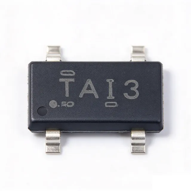
TL431AIDBZR - 2.495V Adjustable Shunt Reference | Texas Instruments
부품 번호: TL431AIDBZR ✓ 활성| 수량 | 단가 | 합계 |
|---|---|---|
| 1 | $0.29 | $0.29 |
| 10 | $0.22 | $2.20 |
| 100 | $0.13 | $13.00 |
| 500 | $0.1 | $50.00 |
| 1,000 | $0.08 | $80.00 |
TL431AIDBZR 개요
A shunt voltage reference is a type of voltage reference IC that regulates voltage by sinking or sourcing current through a parallel (shunt) path, holding the voltage across its terminals constant once the input exceeds a minimum threshold. Within the power-management hierarchy, the TL431 belongs to the family of adjustable shunt regulators, sitting between fixed Zener diodes and series voltage regulators: it offers programmable precision without the dropout constraints of a linear regulator, making it a foundational building block in power management IC design.
Key features include an adjustable output from approximately 2.5V to 36V using two external resistors, a cathode current range of 1 mA to 100 mA, low dynamic output impedance of typically 0.22 ohms, and a temperature coefficient specified over the -40C to +85C industrial range for the A-grade version. The A grade carries a ±1% initial reference tolerance at 25C, tighter than the standard grade's ±2%.
Technically, the TL431 integrates an internal 2.495V bandgap reference driving an operational amplifier whose output controls an output transistor; closing the loop from cathode to reference pin makes the device behave as a precision Zener. Its fast transient response and low output noise make it well-suited to feedback networks in switching power supplies.
Typical applications include isolated flyback and forward converter feedback (driving an optocoupler), adjustable Zener references in battery chargers, voltage monitors and comparators, and precision current-source circuits in industrial and consumer power systems.
A key design consideration: the device requires a minimum cathode current of approximately 1 mA to stay in regulation; below this threshold, accuracy degrades, so bias resistor sizing is critical.
This page synthesizes distributor pricing, pin-to-pin drop-in alternatives, and practical design notes not found in the manufacturer datasheet.
드롭인 대체품: TL431AIDBZR — 동일 패키지, 핀 호환. PCB 재작업이 필요한 다른 패키지 부품은 제외됩니다.
이 시리즈의 변형
다음과 드롭인 호환되는 동일 시리즈 모델: TL431AIDBZR (동일 폼 팩터 및 풋프린트) — 차이점: Package, Reference Voltage (Vref), Adjustable Output Range, Operating Temperature Range, Grade.
빠른 비교 도구 — 나란히 비교할 대체 부품을 선택하십시오:
TL431ACDBZR
✓ 재고 있음
$0.07 / 개
데이터시트 보기 →TL431BIDBZR
📋 참조 대체품 (카탈로그에 없음)
TL432AIDBZR
📋 참조 대체품 (카탈로그에 없음)
ATL431AIDBZR
📋 참조 대체품 (카탈로그에 없음)
KA431
📋 참조 대체품 (카탈로그에 없음)
AZ431
📋 참조 대체품 (카탈로그에 없음)
TL431AIDBZR 최대 정격 & 전기적 특성
| Reference Voltage (Vref) | 2.495 V |
| Reference Tolerance (25C) | ±1% (A grade) |
| Adjustable Output Range | Vref to 36 V |
| Cathode Current Range | 1 mA to 100 mA |
| Maximum Cathode Current | 100 mA |
| Maximum Cathode Voltage | 36 V |
| Dynamic Output Impedance | 0.22 ohm (typical) |
| Grade | A grade (±1%) |
| 동작 온도 범위 | -40C to +85C (Industrial, I suffix) |
| 패키지 | SOT-23-3 (DBZ) |
| 실장 유형 | Surface Mount |
| Type | Adjustable Precision Shunt Regulator / Voltage Reference |
| RoHS 상태 | Compliant |
| 핀 수 | 3 |
| Applications | Automotive, commercial, and military grade thermal stability (per TI product page) |
TL431AIDBZR 핀 구성
| 핀 1 | REF — Reference input, nominal 2.495V threshold |
| 핀 2 | ANODE — Anode terminal (lowest potential terminal) |
| 핀 3 | CATHODE — Cathode terminal, regulated voltage output, 1 mA to 100 mA |
일반적인 애플리케이션
TL431AIDBZR 적합 용도: 6 애플리케이션s: Isolated Flyback Converter Feedback, Adjustable Precision Zener Reference, Voltage Monitor and Threshold Comparator, Precision Constant-Current Source, Battery Charger Regulation Loop, ADC Reference and Analog Level Setting.
Isolated Flyback Converter Feedback
The TL431AIDBZR is the de-facto industry standard for secondary-side voltage regulation in isolated flyback, forward, and LLC power supplies. Its 2.495V reference divides down the output rail through a resistor divider, and the resulting error current drives the LED of an optocoupler that closes the control loop to the primary-side PWM controller (e.g., UC3843 or a dedicated flyback controller). The ±1% A-grade accuracy directly translates to output voltage setpoint accuracy, while the device's low dynamic output impedance of 0.22 ohm typical supports good load transient response. Compensation is implemented with an RC network from cathode to reference; keep cathode current above 1 mA at all loads to preserve regulation across the -40C to +85C industrial range.
추천
Adjustable Precision Zener Reference
Used as a programmable Zener diode, the TL431AIDBZR replaces discrete Zener diodes wherever stable, adjustable clamping or reference voltages are required. By tying cathode to reference, the part clamps at exactly 2.495V; adding a divider sets any clamp voltage from 2.5V to 36V with ±1% accuracy - far tighter than the typical 5% tolerance of discrete Zeners, and with a much sharper knee due to the internal error amplifier. The 1 mA to 100 mA cathode current range covers bias, crowbar, and level-shift duties. Compared with a Zener, the TL431AIDBZR exhibits far lower dynamic impedance (0.22 ohm typical vs tens of ohms), so reference ripple and load sensitivity are dramatically reduced in 5V, 12V, and 24V industrial subsystems.
추천
Voltage Monitor and Threshold Comparator
The TL431AIDBZR functions as a comparator with a built-in 2.495V reference: when the divider at the reference pin exceeds 2.495V, the cathode pulls low, enabling undervoltage/overvoltage detection without a separate reference IC and comparator. This two-in-one behavior saves board area and BOM cost in battery chargers, power-good indicators, and protection latches. A pull-up resistor from a supply to the cathode produces a clean logic-level output; adding hysteresis resistors creates trip windows for battery management cutoffs. Because the A grade holds ±1% reference tolerance, threshold accuracy can approach ±2% total including divider resistor error across -40C to +85C, sufficient for most consumer and industrial monitoring functions.
추천
Precision Constant-Current Source
With a sense resistor between cathode and reference and a load in the anode path, the TL431AIDBZR forms a precision 2-terminal current source: the reference holds 2.495V across the sense resistor, setting load current as Is = 2.495V / Rs. This topology delivers currents from a few milliamps up to the 100 mA cathode limit with accuracy governed by the ±1% reference tolerance and resistor precision, far better than discrete transistor current sources that depend on Vbe. Typical uses include LED bias, laser diode biasing, sensor excitation, and NTC linearization in industrial instruments. Watch power dissipation in the device: with a 24V supply and 20 mA current, dissipation reaches roughly 0.47W, requiring attention to SOT-23-3 thermal limits.
추천
Battery Charger Regulation Loop
In linear and switching battery chargers, the TL431AIDBZR sets both the charge-voltage regulation point and the charge-termination threshold. Its 2.495V reference scaled by the resistor divider defines float voltages for 3.7V Li-ion, 6V lead-acid, and 12V systems, while ±1% accuracy protects cells from overcharge - critical because Li-ion charge voltage tolerance is typically ±1%. The device also serves in constant-current phases when combined with a sense resistor in the cathode-feedback network. Its fast response supports the CC-to-CV transition without overshoot, and the low 1 mA minimum cathode current keeps losses negligible at charge termination, improving overall charger efficiency across the industrial temperature range.
추천
ADC Reference and Analog Level Setting
Where a modest-accuracy analog reference or bias level is needed, the TL431AIDBZR provides a low-cost, adjustable rail for ADC full-scale setting, op-amp offset biasing, and window-comparator thresholds in data acquisition front ends. Scaled from 2.5V to 36V and filtered with an RC to reduce broadband noise, it suits 8- to 10-bit systems where the ±1% initial tolerance and industrial temperature stability are adequate. For 12-bit and higher systems, pair it with a precision series reference and use the TL431 only as a supervisor. XAIPART also stocks high-resolution ADCs such as the AD7683BCPZRL and AD7691BCPZRL, whose front-end biasing networks commonly employ TL431-class shunt references for threshold generation.
추천
추천 제품 요약
엔지니어링 참조 데이터: TL431AIDBZR — 비교, 설계 지침 및 규정 준수 정보.
선택 가이드
대체품과의 비교
| 파라미터 | 이 제품 | TL431BIDBZR | TL431ACDBZR | TL432AIDBZR | ATL431AIDBZR | KA431 | AZ431 |
|---|---|---|---|---|---|---|---|
| Package | SOT-23-3 (DBZ) | SOT-23-3 (DBZ) - same | SOT-23-3 (DBZ) - same | SOT-23-3 (DBZ) - same package, different pin assignment | SOT-23-3 (DBZ) - same | SOT-23-3 | SOT-23-3 |
| Brand | Texas Instruments | Texas Instruments | Texas Instruments | Texas Instruments | Texas Instruments | onsemi | Diodes Incorporated |
| Reference Voltage | 2.495 V | 2.495 V | 2.495 V | 2.495 V | 2.5 V class | 2.495 V | 2.5 V class |
| Maximum Cathode Current | 100 mA | 100 mA | 100 mA | 100 mA | 20 mA | 100 mA | 100 mA |
| Adjustable Output Range | Vref to 36 V | Vref to 36 V | Vref to 36 V | Vref to 36 V | Vref to 36 V | Vref to 36 V | Vref to 36 V |
주요 차별점
- ±1% A-grade accuracy at commodity price (vs TL431ACDBZR)
- Industrial temperature range with wide 36V compliance (vs TL431ACDBZR)
- Full 100 mA cathode current capability (vs ATL431AIDBZR)
설계 노트
Ensure at least 1 mA of continuous cathode current flows to keep the TL431AIDBZR in regulation; below this the reference accuracy degrades and the output may drift upward. In optocoupler feedback designs, the bias resistor feeding the TL431/optocoupler node must supply the optocoupler LED current plus the 1 mA minimum, especially at minimum load and high temperature. Conversely, respect the 100 mA maximum cathode current - add series resistance if a fault condition could dump full supply voltage across the part.
The TL431 is an amplifier with finite bandwidth and phase margin; it can oscillate when driving low-ESR ceramic capacitors or optocoupler LEDs with large LED shunt resistance. TI application guidance and widely published TL431 compensation references recommend checking the loop with the actual capacitor: if instability appears, add a series resistor of a few ohms to the capacitor or increase its ESR. Simulate or measure the closed flyback loop across line and load, and verify phase margin exceeds 45 degrees at worst case.
Place the resistor divider as close to the REF pin as possible and keep the divider trace short and away from switching nodes to avoid coupling ripple into the reference. Kelvin-connect the divider top to the point of regulation (e.g., the output connector rather than the regulator output capacitor) so lead drop does not degrade the ±1% setpoint. A small compensation network directly at the cathode-to-REF pins minimizes loop area and improves noise immunity in SMPS environments.
Do not assume the TL432 is pin-identical to the TL431: the TI datasheet explicitly states the TL432 has exactly the same electrical specifications but different pinouts in the DBV, DBZ, and PK packages. Substituting a TL432AIDBZR onto a TL431 DBZ footprint without checking the pin map will connect anode and cathode incorrectly. Also verify grade suffixes when sourcing from multiple manufacturers - KA431 and AZ431 grade/temperature options do not map one-to-one onto TI's B/A/standard scheme.
규정 준수 정보
RoHS compliance inferred from current-production TI/DigiKey/Mouser listings. Obtain formal REACH and conflict-minerals declarations from the TI product page. The ATL431 sibling is the AEC-Q100 capable family member.
