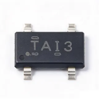
TL431CDBZRG4 - 36V Adjustable Shunt Voltage Reference | TI
부품 번호: TL431CDBZRG4 ✓ 활성| 수량 | 단가 | 합계 |
|---|---|---|
| 1 | $0.42 | $0.42 |
| 10 | $0.31 | $3.10 |
| 100 | $0.19 | $19.00 |
| 500 | $0.14 | $70.00 |
| 1,000 | $0.11 | $110.00 |
| 3,000 | $0.09 | $270.00 |
TL431CDBZRG4 개요
A shunt regulator or shunt voltage reference is a two-terminal-style (here three-terminal, with a REF pin) precision device that regulates voltage by sinking current through itself when the sensed voltage exceeds the internal reference threshold. Within the power-management hierarchy it sits under voltage references and shunt regulators, complementing series LDO regulators. Because it behaves like an error amplifier with an integrated precision bandgap reference, it is widely used as the feedback element in isolated and non-isolated switching power supplies.
Key features of the TL431CDBZRG4 include the adjustable output range of 2.495 V to 36 V set with a resistive divider on the REF pin, up to 100 mA cathode sink current, low typical output impedance of 0.2 ohm, and low output noise in the 0.2 uV-range band typical of the TL431 family. The TL431C temperature grade covers commercial operating ranges with specified thermal stability, making it suitable for consumer and industrial environments.
Technically, the TL431 integrates a 2.495 V bandgap reference, an operational amplifier, and an output transistor. When the REF pin voltage rises above the internal 2.495 V threshold, the output stage conducts cathode current, clamping the voltage. This behaves like an ideal zener diode with sharp knee characteristics, far tighter tolerance and lower dynamic impedance than passive zeners, and it can also serve as a comparator with reference in voltage-monitoring circuits.
Typical applications include the feedback loop of flyback and forward isolated SMPS designs driving an optocoupler, secondary-side voltage regulation in AC-DC adapters and chargers, overvoltage protection crowbar circuits, and precision voltage monitoring in industrial control and battery chargers.
A key design consideration: ensure minimum cathode bias current (on the order of 1 mA) so the device remains in regulation, and compensate feedback loops carefully because the TL431 contributes a pole and gain that affect optocoupler loop stability.
This page synthesizes verified distributor data, drop-in alternatives, pricing tiers, and practical design notes not found in the manufacturer datasheet.
드롭인 대체품: TL431CDBZRG4 — 동일 패키지, 핀 호환. PCB 재작업이 필요한 다른 패키지 부품은 제외됩니다.
이 시리즈의 변형
다음과 드롭인 호환되는 동일 시리즈 모델: TL431CDBZRG4 (동일 폼 팩터 및 풋프린트) — 차이점: Package, Reference Voltage (Vref), Adjustable Output Voltage Range, Minimum Cathode Current for Regulation, Operating Temperature Range.
빠른 비교 도구 — 나란히 비교할 대체 부품을 선택하십시오:
TL431CDBZR
✅ 드롭인✓ 재고 있음
$0.028 / 개
데이터시트 보기 →TL431ACDBZR
✅ 드롭인 ⚠️ 사양 미검증✓ 재고 있음
$0.07 / 개
데이터시트 보기 →TL431IDBZR
✅ 드롭인✓ 재고 있음
$0.08 / 개
데이터시트 보기 →TL431LIACDBZR
✅ 드롭인📋 참조 대체품 (카탈로그에 없음)
LM431SACM3X
✅ 드롭인📋 참조 대체품 (카탈로그에 없음)
KA431AZTA
✅ 드롭인📋 참조 대체품 (카탈로그에 없음)
AZ431AZ-ATRE1
✅ 드롭인📋 참조 대체품 (카탈로그에 없음)
TL431CDBZRG4 최대 정격 & 전기적 특성
| Reference Voltage (Vref) | 2.495 V |
| Reference Tolerance | ±2.2% |
| Adjustable Output Voltage Range | Vref (2.495 V) to 36 V |
| Cathode Current Range | 1 mA to 100 mA |
| Maximum Cathode Current | 100 mA |
| Typical Output Impedance | 0.2 ohm |
| Device Type | Adjustable Precision Shunt Regulator / Voltage Reference |
| Number of Terminals | 3 |
| 패키지 | SOT-23-3 (DBZ) |
| 실장 유형 | Surface Mount |
| Temperature Grade | C (commercial temperature range) |
| Packaging | Tape & Reel (R suffix) |
| RoHS / Green Status | G4 green, RoHS compliant |
| 출력 노이즈 | Low output noise (typical TL431 family, 0.2 uV-range per datasheet noise figure) |
TL431CDBZRG4 핀 구성
| 핀 1 | REF — Reference input, threshold approximately 2.495 V |
| 핀 2 | ANODE — Anode terminal, connect to circuit ground / low side |
| 핀 3 | CATHODE — Cathode terminal, regulated output / sink current terminal |
일반적인 애플리케이션
TL431CDBZRG4 적합 용도: 6 애플리케이션s: SMPS Optocoupler Feedback, AC-DC Adapters and Chargers, Overvoltage Protection Crowbar, Precision Voltage Monitoring and Comparator, Programmable Shunt Regulation and Series-Pass Error Amp, Data Acquisition and ADC Reference Supervision.
SMPS Optocoupler Feedback
The TL431CDBZRG4 is the de facto industry standard secondary-side error amplifier in isolated flyback and forward converters. Its internal 2.495 V reference compares a resistor-divided output voltage, and the resulting cathode current drives an optocoupler LED (such as a PC817 or similar 4-pin phototransistor coupler) to modulate the primary-side PWM controller. The 36 V cathode rating covers 5 V, 12 V, 19 V, and 24 V adapter outputs, while the 0.2 ohm output impedance ensures a stiff correction signal. The main engineering effort is type-II or type-III loop compensation around the TL431-optocoupler path to achieve stable gain and phase margin.
추천
AC-DC Adapters and Chargers
Phone chargers, laptop adapters, and battery chargers use the TL431CDBZRG4 to hold the output voltage within tight tolerance across load and line transients. The C-grade 2.2%-class reference tolerance, combined with 1%-tolerance divider resistors, typically yields 3% or better total output regulation, adequate for USB-class outputs. Its low cost in reel quantities (below $0.10 at 3000 pieces as of 2026-10-12) and tiny SOT-23-3 footprint fit dense charger PCBs. Minimum cathode current of about 1 mA is trivially satisfied from the adapter output, and the 100 mA sink capability accommodates wide optocoupler LED current swings for robust pulse-skipping control at light load.
추천
Overvoltage Protection Crowbar
In crowbar protection circuits, the TL431CDBZRG4 monitors a supply rail through a divider on its REF pin; when the rail exceeds the programmed threshold (set between 2.495 V and 36 V), the cathode pulls down and triggers an SCR gate or a MOSFET shut-off, crowbarring the supply before damage occurs. The sharp knee of the TL431 - far sharper than a zener diode - gives a precise trip point with low hysteresis drift over temperature. The 100 mA sink capability directly drives small SCR gates, and the SOT-23-3 package minimizes protection-circuit board area on densely populated power distribution boards.
추천
Precision Voltage Monitoring and Comparator
The TL431CDBZRG4 doubles as a comparator with a built-in 2.495 V reference: when the REF pin falls below 2.495 V the cathode stays high; when it rises above, the cathode snaps low, driving LEDs, logic, or MCU interrupt inputs. This suits low-battery indicators, power-good supervision, and threshold alarms in industrial controllers. Compared with a discrete reference plus comparator, one SOT-23-3 device replaces two parts and removes reference tolerance stacking. The C-grade tolerance and 0.2 ohm output impedance deliver consistent trip thresholds, and the adjustable range up to 36 V covers 24 V industrial bus monitoring directly.
추천
Programmable Shunt Regulation and Series-Pass Error Amp
Beyond shunt use, the TL431CDBZRG4 serves as the error amplifier in discrete series regulators: its cathode drives the gate or base of a series pass transistor while REF monitors the divided output, forming a low-cost adjustable regulator for custom rail voltages from about 2.5 V to 36 V. This appears in lab-style bench supplies, LED driver bias rails, and analog front-end biasing where no suitable fixed LDO exists. The low 0.2 ohm output impedance contributes high loop gain for tight line and load regulation; external frequency compensation on the REF network is required since the TL431 adds gain and a pole to the regulation loop.
추천
Data Acquisition and ADC Reference Supervision
Precision ADC signal chains - such as those built around AD7683 or AD7656 converters - require power-good supervision and threshold monitoring of analog rails. The TL431CDBZRG4 provides a low-cost 2.495 V-threshold monitor for 3.3 V, 5 V, and ±15 V analog supplies, asserting a flag when any rail drifts beyond its programmed window. Where a rough adjustable reference is acceptable for coarse conversion ranges, the TL431 can also serve as a budget shunt reference with filtering. Its commercial C-grade tolerance and 100 mA capability make it ideal for monitoring duties, while precision conversions rely on the ADC's dedicated reference input.
추천
추천 제품 요약
엔지니어링 참조 데이터: TL431CDBZRG4 — 비교, 설계 지침 및 규정 준수 정보.
선택 가이드
대체품과의 비교
| 파라미터 | 이 제품 | TL431CDBZR | TL431IDBZR | LM431SACM3X | KA431AZTA |
|---|---|---|---|---|---|
| Package | SOT-23-3 (DBZ) | SOT-23-3 (DBZ) - same | SOT-23-3 (DBZ) - same | SOT-23-3 - same | SOT-23-3 - same |
| Brand | Texas Instruments | Texas Instruments | Texas Instruments | onsemi | onsemi |
| Reference Voltage | 2.495 V | 2.495 V | 2.495 V | 2.5 V class | 2.495 V class |
| Max Output Voltage | 36 V | 36 V | 36 V | 36 V class | 36 V class |
| Max Cathode Current | 100 mA | 100 mA | 100 mA | 100 mA class | 100 mA class |
| Temperature Range | C grade (commercial) | C grade (commercial) | I grade (industrial) | commercial class | 0C to +125C (TA) |
| Unit Price (qty 1, as of 2026-10-12) | ~$0.42 | ~$0.35 | ~$0.40 | ~$0.30 | ~$0.25 |
주요 차별점
- Green (G4) packaging with identical die to TL431CDBZR (vs TL431CDBZR)
- Extended industrial temperature option in same footprint (vs TL431IDBZR)
- Full TI datasheet and second-source ecosystem (vs KA431AZTA)
설계 노트
Maintain at least the minimum cathode current (about 1 mA) at all times, including at no-load, or the TL431CDBZRG4 will come out of regulation and the output will drift upward. Provide a bias resistor from a supply that guarantees this current through the full temperature range. Also respect the 36 V cathode absolute rating and 100 mA maximum sink current; a series resistor is mandatory in crowbar applications where fault current could otherwise exceed the package limit.
In optocoupler SMPS feedback loops, the TL431 contributes both gain and a dominant pole; use a type-II compensation network (RC plus feedforward capacitor around the TL431) and place a resistor in series with the optocoupler LED to decouple the fast loop from the slow loop, per standard flyback compensation practice in the TI datasheet application section. Poor compensation shows up as output oscillation at low line or light load - verify phase margin across the full operating envelope.
Place the REF divider resistors close to the REF pin and use 1%-tolerance, low-TCR resistors to preserve output accuracy; leakage across the REF node from nearby high-voltage traces can shift the threshold. Keep the cathode trace short and add a small ceramic capacitor (with care for stability - large capacitance directly on cathode can destabilize the shunt) according to TI stability guidance for capacitive loading ranges.
규정 준수 정보
G4 suffix denotes TI green and RoHS-compliant packaging per DigiKey/TI product listings. AEC-Q100 qualification not indicated for the C-grade commercial part; use TL431AQDBZR for automotive-grade needs.