Allegro MicroSystems

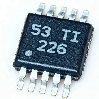
ACS712 - Hall-Effect Linear Current Sensor IC | Allegro MicroSystems

MPN: ACS712 ✗ End of Life
In Stock Ships in 1-3 business days
VCC/2 (≈2.5 V at 5 V supply) Vdss ±5 A (ACS712ELCTR-05B-T) Id 1.2 mΩ (typical) Rds(on) 8-SOIC (3.90 mm width), surface mount Package
From $1.16 USD / Unit
MOQ: 1 |
Price updated: 2026-10-11
Volume Pricing
Qty Unit Price Extended
1 $1.95 $1.95
10 $1.72 $17.20
100 $1.48 $148.00
500 $1.31 $655.00
1,000 $1.16 $1,160.00
ℹ️ All prices are in USD

ACS712 Overview

The Allegro MicroSystems ACS712 is a fully integrated, Hall-effect-based linear current sensor IC housed in an 8-pin SOIC (LC) package that delivers economical and precise solutions for AC or DC current sensing in industrial, commercial, and communications systems. The ACS712 family is offered in three factory-trimmed primary-current ranges: ±5 A (ACS712-05B), ±20 A (ACS712-20B), and ±30 A (ACS712-30B), with sensitivity scaling inversely with range at 185 mV/A, 100 mV/A, and 66 mV/A respectively.

A Hall-effect current sensor is a non-contact transducer that exploits the Lorentz force principle: current flowing through an internal low-resistance copper conduction path generates a magnetic field proportional to the amperage, which an on-chip Hall element converts into a ratiometric analog output voltage. This places Hall-effect current sensors at the same level in the sensing hierarchy as shunt-resistor amplifiers (e.g., INA219) and current transformers (CTs); Hall sensors are uniquely galvanically isolated, compact, and bidirectional by construction, while shunt amplifiers offer higher bandwidth and CTs require AC excitation.

Key features include a galvanically isolated current path (no shunt resistor required), sub-ohm internal conductor resistance (1.2 mΩ typical) for minimal insertion loss, a 5.0 µs output rise time in response to step input, and a 50 kHz small-signal bandwidth. The device operates from a single 5 V supply, draws a low quiescent current, and provides a stable zero-current output of VCC/2 (≈2.5 V at 5 V supply) for bidirectional measurement around the mid-rail. Proprietary integrated digital temperature compensation trims sensitivity and offset across the −40°C to +85°C operating range.

The architecture uses a precise, low-offset linear Hall circuit placed near the copper conduction path; close proximity between magnetic signal and transducer maximizes device accuracy. Differential sensing cancels external stray fields, and a low-impedance output stage buffers the ratiometric output for direct connection to an ADC input or comparator threshold.

Typical applications include motor control and load detection in robotics and white goods, switched-mode power supply feedback for overcurrent protection, battery management in e-bikes and UPS systems, and 3D printer / CNC spindle current monitoring. The SOIC-8 footprint suits both hand-soldered breakouts and high-density SMT production. When designing, place a low-ESR bypass capacitor close to VCC and route the primary current conductor through the on-package copper trace to maintain specified accuracy; verify the output zero point at no current before each conversion to remove thermal drift.

Drop-in alternatives for ACS712 — same package, pin-to-pin compatible. Different-package parts requiring PCB rework are excluded.

Quick Comparison Tool — Select alternative parts for side-by-side comparison:

ACS724LLCTR-05B

✅ Drop-In
📦 8-SOIC
modern successor ±5 A range, 120 kHz bandwidth vs 50 kHz, identical 8-SOIC footprint

📋 Reference alternative (not in catalog)

ACS724LLCTR-20A

✅ Drop-In
📦 8-SOIC
modern successor ±20 A range, 120 kHz bandwidth vs 50 kHz, identical 8-SOIC footprint

📋 Reference alternative (not in catalog)

ACS724LLCTR-30A

✅ Drop-In
📦 8-SOIC
modern successor ±30 A range, 120 kHz bandwidth vs 50 kHz, identical 8-SOIC footprint

📋 Reference alternative (not in catalog)

ACS723LLCTR-05AB

✅ Drop-In
📦 8-SOIC
modern successor ±5 A, lower 0.6 mΩ conductor resistance, identical 8-SOIC pinout

📋 Reference alternative (not in catalog)

ACS723LLCTR-20AB

✅ Drop-In
📦 8-SOIC
modern successor ±20 A, lower 0.6 mΩ conductor resistance, identical 8-SOIC pinout

📋 Reference alternative (not in catalog)

ACS758LCB-050B-PFF-T

✅ Drop-In
📦 8-SOIC
modern ±50 A high-current successor, 120 kHz bandwidth, larger conduction path, identical 8-SOIC footprint

📋 Reference alternative (not in catalog)

ACS712 Maximum Ratings & Electrical Characteristics

Sensor Type Hall-Effect, Linear, Open-Loop
Number of Channels 1
Primary-Side Current Range (±5A variant) ±5 A (ACS712ELCTR-05B-T)
Primary-Side Current Range (±20A variant) ±20 A (ACS712ELCTR-20A-T)
Primary-Side Current Range (±30A variant) ±30 A (ACS712ELCTR-30A-T)
Sensitivity (±5A variant) 185 mV/A (typical)
Sensitivity (±20A variant) 100 mV/A (typical)
Sensitivity (±30A variant) 66 mV/A (typical)
Zero-Current Output Voltage VCC/2 (≈2.5 V at 5 V supply)
Supply Voltage (VCC) 4.5 V to 5.5 V (5 V typical)
Internal Conductor Resistance 1.2 mΩ (typical)
Output Response Time 5 µs (typical, di/dt = Ip/A)
Small-Signal Bandwidth 50 kHz
Operating Temperature Range -40°C to +85°C
Current Direction Bidirectional (AC and DC)
Package 8-SOIC (3.90 mm width), surface mount

ACS712 Pin Configuration

SOIC-8 Package Pinout Diagram SOIC-8 8-pin small outline IC, 3.9x4.9mm, P1.27mm, JEDEC MS-012. 1 8 2 7 3 6 4 5 SOIC-8
Pin 1 VCC — 5 V power supply input
Pin 2 OUT — Ratiometric analog voltage output (VCC/2 at zero current)
Pin 3 FILTER — External bandwidth-setting capacitor; leave open for full bandwidth or connect 1 nF to GND to limit bandwidth
Pin 4 GND — Common ground
Pin 5 IP+ — Primary current input/conduction pin (high-current path)
Pin 6 IP+ — Primary current input/conduction pin (paralleled internally with pin 5)
Pin 7 IP- — Primary current return/conduction pin (high-current path)
Pin 8 IP- — Primary current return/conduction pin (paralleled internally with pin 7)

Typical Applications

ACS712 is suitable for 6 applications: BLDC Motor Control and Inverter Feedback, Switched-Mode Power Supply Overcurrent Protection, Battery Management and E-Bike Current Monitoring, Robotics and 3D Printer Load Detection, Industrial PLC and Load Monitoring, Mains AC Current Monitoring and Smart Meters.

🏭

BLDC Motor Control and Inverter Feedback

The ACS712 is used as a non-isolated analog feedback element in low-voltage brushless DC motor control loops, providing a ratiometric proportional output that scales linearly with phase current. With 50 kHz small-signal bandwidth and 5 µs step response, the device can resolve PWM-edge current ripple for sensorless FOC firmware; the VCC/2 zero-current reference is convenient for ADC sampling around mid-rail. Compared with shunt-resistor amplifiers, the ACS712's galvanically isolated copper conductor introduces no common-mode swing to the low-voltage control electronics, simplifying PCB layout.

⚡

Switched-Mode Power Supply Overcurrent Protection

In AC/DC and DC/DC converters, the ACS712 measures primary-side or secondary-side current with galvanic isolation, enabling safe overcurrent thresholding and hiccup-mode fault response in Switched-Mode Power Supply (SMPS) designs. The 50 kHz bandwidth comfortably spans the typical 50/60 Hz mains and 1-2 kHz switching frequencies used in power-factor-correction circuits, while the 1.2 mΩ internal conductor resistance minimises insertion loss. Its ratiometric output can be compared directly with a comparator reference to trigger a controller's fault pin.

🔋

Battery Management and E-Bike Current Monitoring

The ACS712 measures pack charge and discharge current on electric bicycles, scooters, and uninterruptible power supplies without breaking the high-current loop with a shunt and amplifier. The ±30 B variant monitors up to ±30 A continuously with 66 mV/A sensitivity, providing accurate SoC feedback to the battery management microcontroller. Integrated temperature compensation keeps the reading stable from cold-start (−40°C) to mid-pack discharge, while the bidirectional ratiometric output is sampled directly at the BMS AFE.

🏭

Robotics and 3D Printer Load Detection

In robotic arm and 3D printer motor control, the ACS712 senses per-driver load current to detect end-effector collisions, stalled steppers, and extruder jams. The 185 mV/A sensitivity of the −05B variant gives high-resolution measurement of small motor currents, while the 5 µs response time triggers a stall interrupt inside one PWM cycle of the fault being detected. Galvanic isolation simplifies high-current motor routing and keeps 5 V logic out of the high-current loop, an important factor in low-cost 3D printers.

🏭

Industrial PLC and Load Monitoring

The ACS712 is widely deployed on industrial Programmable Logic Controller (PLC) analogue input modules and load-management relays to measure current on each phase of a motor or heater without external shunts. The wide operating temperature range (−40°C to +85°C) and factory-trimmed sensitivity across variants support multi-load control panels spanning −05B, −20A, and −30B for mixed current ratings. The SOIC-8 surface-mount package suits both wave-soldered backplanes and reflow-printed daughter cards in industrial environments.

🌐

Mains AC Current Monitoring and Smart Meters

For line-voltage AC current sensing in smart meters, energy-monitoring outlets, and home energy displays, the ACS712 measures 50/60 Hz mains current with full galvanic isolation from low-voltage electronics. The 50 kHz bandwidth captures up to several harmonics for power-quality analysis, and the bidirectional centre-tap output directly represents the AC waveform without rectification. Using the ACS712, designers avoid the bulky current transformer footprint or the safety hazard of a direct shunt in line-voltage conductors.

Recommended Products Summary

ACS724LLCTR-30A pin-compatible ±30 A successor with 120 kHz bandwidth Used in: BLDC Motor Control and Inverter Feedback DRV8323RS three-phase FOC gate driver companion part Used in: BLDC Motor Control and Inverter Feedback UCC28600D Texas Instruments Used in: Switched-Mode Power Supply Overcurrent Protection ACS724LLCTR-20A modern pin-compatible successor for new designs Used in: Switched-Mode Power Supply Overcurrent Protection ACS712ELCTR-30B-T ±30 A factory variant for pack current sensing Used in: Battery Management and E-Bike Current Monitoring BQ76952 Texas Instruments Used in: Battery Management and E-Bike Current Monitoring TMC2209 silent stepper driver companion part Used in: Robotics and 3D Printer Load Detection ACS712ELCTR-05B-T ±5 A factory variant for low-current motor Used in: Robotics and 3D Printer Load Detection XMC1301Q040F0008ABXUMA1 Infineon Used in: Industrial PLC and Load Monitoring, Mains AC Current Monitoring and Smart Meters ACS723LLCTR-50AB modern ±50 A successor for high-current channels Used in: Industrial PLC and Load Monitoring ACS712ELCTR-20A-T ±20 A factory variant for residential load Used in: Mains AC Current Monitoring and Smart Meters
What is the ACS712 and how does it measure current?
The Allegro ACS712 is a galvanically isolated, Hall-effect-based linear current sensor IC in an 8-pin SOIC package that measures AC or DC current up to ±5 A, ±20 A, or ±30 A depending on the -05B, -20A, or -30B variant. According to the Allegro ACS712 datasheet, load current flows through an internal copper conductor generating a magnetic field that an on-chip Hall element converts into a ratiometric analog voltage centered at VCC/2 (≈2.5 V at 5 V), with sensitivity of 185, 100, or 66 mV/A respectively.
What is the output voltage sensitivity of the ACS712?
The ACS712 sensitivity scales inversely with primary current range: the -05B variant outputs 185 mV/A, the -20A variant outputs 100 mV/A, and the -30B variant outputs 66 mV/A (per the Allegro datasheet). At zero primary current the ratiometric output sits at VCC/2, so engineers measure current by computing (VOUT − VCC/2) / sensitivity. Use the factory-trimmed sensitivity value, not a guessed one, to preserve accuracy.
What is the supply voltage requirement for the ACS712?
The ACS712 operates from a single 4.5 V to 5.5 V supply with a typical value of 5.0 V; its output is ratiometric, so the zero-current output (VCC/2) and the sensitivity both scale linearly with supply voltage. According to the Allegro datasheet the device draws very low quiescent current, and a 100 nF ceramic bypass capacitor placed close to VCC and GND is required for stable measurement.
Where can I buy the ACS712 online and what is the price?
The ACS712 (e.g., ACS712ELCTR-05B-T, ACS712ELCTR-20A-T, ACS712ELCTR-30B-T) is in stock at major distributors including DigiKey, Mouser, and Arrow, with qty-1 pricing starting near $1.95 USD as of 2026-10-11. Volume pricing drops to roughly $1.16 USD per unit at qty 1000. Note that the ACS712 family is now flagged Not-for-New-Design (NRND) by Allegro; recommended successors include the ACS724 and ACS723 series.
What is the lead time for ACS712 orders?
Lead times for ACS712 listed distributor stock (ACS712ELCTR-05B-T, -20A-T, -30B-T) are typically 2 to 4 weeks as of 2026-10-11, but the part is flagged Not-for-New-Design (NRND) by Allegro MicroSystems. For new designs, Allegro recommends the ACS724 family (5 V/3.3 V versions) and ACS723 family as modern pin-compatible successors; sourcing the original ACS712 for new production should be confirmed with the distributor.
What is the difference between the ACS712-05B, ACS712-20A, and ACS712-30B variants?
The three ACS712 variants differ only in primary current range and sensitivity per the Allegro datasheet: -05B handles ±5 A at 185 mV/A (highest sensitivity, best for low-current signals), -20A handles ±20 A at 100 mV/A (general purpose), and -30B handles ±30 A at 66 mV/A (highest range, lowest sensitivity, best for motor/inverter loads). All three share the same 8-pin SOIC (LC) footprint, 5 V supply, VCC/2 zero-current output, and 50 kHz bandwidth, so they are mechanically interchangeable.
What is the best drop-in replacement for the ACS712?
The best drop-in pin-compatible replacements for the ACS712 are Allegro's ACS724 series (ACS724LLCTR-05B/10B/20B/30B/40B/50B) and ACS723 series, both in the same 8-pin SOIC package with similar sensitivity/offset scaling and improved bandwidth. According to the Allegro migration guidance and Digi-Key cross-reference data the ACS724 family extends to ±50 A and supports both 5 V and 3.3 V operation with better thermal performance; for low-power applications the INA219 is also a common parametric substitute but is NOT a drop-in (different I2C/SOIC-10 package).
What are the key specifications of ACS712 that engineers should know?
Key ACS712 specifications per the Allegro datasheet are: 8-pin SOIC package; 5 V single supply; ratiometric output at VCC/2 ≈2.5 V; sensitivity of 185 mV/A (-05B), 100 mV/A (-20A), or 66 mV/A (-30B); 50 kHz small-signal bandwidth; 5 µs output rise time; 1.2 mΩ internal conductor resistance for minimal insertion loss; ±1.5% typical linearity at 25°C; bidirectional AC/DC measurement; −40°C to +85°C operating range; and integrated digital temperature compensation trimming both sensitivity and offset drift.
ACS712 vs INA219 - which is better for microcontroller current sensing?
The ACS712 (Hall effect) and INA219 (shunt + amplifier) trade off isolation and bandwidth: the ACS712 is galvanically isolated, fully bidirectional, gives a ratiometric analog output, and operates up to 50 kHz bandwidth, while the INA219 uses an external shunt resistor (typically 0.1 Ω, giving ±3.2 A or ±6.4 A range), reaches higher accuracy via 12-bit I2C ADC, and offers on-board averaging. Choose the ACS712 when you need galvanic isolation, single-rail simplicity, or AC measurement; choose the INA219 when you need digital readout, higher ADC resolution, or single-digit-mA accuracy. They are NOT pin-compatible - the INA219 uses SOIC-10/8 with I2C interface.
Where can I download the ACS712 datasheet PDF?
The official Allegro MicroSystems ACS712 datasheet PDF is hosted at https://www.allegromicro.com/~/media/files/datasheets/acs712-datasheet.ashx (referenced by the manufacturer). Mirror copies are also available on distributor sites including DigiKey product detail pages and SparkFun (cdn.sparkfun.com/assets/4/a/a/0/8/ACS712.pdf). The datasheet contains the complete electrical characteristics table, application circuit, and tape-and-reel packaging drawing for the 8-SOIC (LC) variant.
Where can I find the ACS712 pinout diagram?
The ACS712 pinout for the 8-pin SOIC (LC) package is illustrated on page 1 of the Allegro datasheet and on most breakout-board vendor pages (e.g., SparkFun). Pin functions are: 1 VCC, 2 OUT (ratiometric analog), 3 FILTER (external capacitor for bandwidth setting), 4 GND, 5 and 6 IP+ (primary current input), 7 and 8 IP− (primary current return). The primary current path is between pins 1-4 (IP+) and 5-8 (IP-), and the four conduction pins must all be soldered for low-resistance current handling.
What is the operating temperature range of the ACS712?
The Allegro ACS712 operates from −40°C to +85°C across all three variants (-05B, -20A, -30B), per the published electrical characteristics table. Internal digital temperature compensation trims both sensitivity drift and offset drift across this range, so the device stays within datasheet accuracy without external calibration. Operate below 85°C ambient and consider derating primary current if the on-package power dissipation (Ip² × 1.2 mΩ) raises the die temperature further.
Can the ACS712 measure AC current?
Yes. The ACS712 measures both AC and DC current from DC up to 50 kHz small-signal bandwidth, with a 5 µs output rise time in response to step input, because the underlying Hall element responds to instantaneous magnetic field rather than rectified value. For AC current measurement, sample at well above twice the line frequency (≥2 ksamples/s for 50/60 Hz mains) and compute RMS in software; the galvanic isolation also makes the ACS712 safer for line-voltage monitoring than a direct shunt resistor.
When should I choose the ACS712 over the ACS724 or ACS723?
Choose the original ACS712 only for legacy or repair-replacement scenarios where the SOIC-8 footprint and VCC/2 zero-current convention are already established. For new designs, Allegro recommends the ACS724 family (5 V or 3.3 V versions, ±5 A to ±50 A ranges, 120 kHz bandwidth, better thermal performance) and the ACS723 family (smaller SOIC-8 footprint, lower primary conductor resistance). All three share the same 8-SOIC pinout, so a board layout can be reused with a simple BOM swap.
How do I wire the ACS712 to an Arduino or ESP32?
To wire the ACS712 to an Arduino (or ESP32) ADC input, connect VCC (pin 1) to the 5 V rail (note: ESP32 3.3 V input ADC is compatible but output swing is reduced), GND (pin 4) to common ground, leave FILTER (pin 3) open or tie to ground via 1 nF capacitor, and read OUT (pin 2) with the MCU ADC. Rout the primary current in/out through pins 1-4 (IP+) and 5-8 (IP-) with adequate trace width. Use the formula I = (VOUT − VCC/2) / sensitivity, with sensitivity 185, 100, or 66 mV/A per the variant. Note that Allegro now lists the ACS712 as Not-for-New-Design (NRND) - the ACS724 family is the recommended modern pin-compatible successor.

Engineering reference data for ACS712 — comparison, design guidance, and compliance information.

Selection Guide

Choose the Allegro ACS712 for low-cost AC/DC current sensing applications where the original ±5 A, ±20 A, or ±30 A range, 50 kHz bandwidth, and 8-SOIC footprint meet the design requirement and where the NRND (Not-for-New-Design) status is acceptable for repair replacement or maintenance. For NEW designs in 2026, prefer the ACS724LLCTR family (better than 120 kHz bandwidth, dual 3.3 V/5 V operation, ±50 A top range) or the ACS723LLCTR family (lower 0.6 mΩ conductor resistance, smaller SOIC-8W footprint) - all three share the same SOIC-8 pinout, enabling drop-in board reuse while gaining improved thermal and bandwidth performance. Choose the INA219 (shunt+amplifier) instead when you need digital I²C readout, higher ADC resolution, or milliamp-level accuracy - but be prepared to redesign the PCB footprint since INA219 uses SOIC-10 / SOIC-8W with different pinout.

Comparison with Alternatives

Parameter This Product ACS724LLCTR-05B ACS724LLCTR-20A ACS724LLCTR-30A ACS723LLCTR-05AB ACS758LCB-050B-PFF-T
Brand Allegro MicroSystems Allegro MicroSystems Allegro MicroSystems Allegro MicroSystems Allegro MicroSystems Allegro MicroSystems
Package 8-SOIC (LC) 8-SOIC - same 8-SOIC - same 8-SOIC - same 8-SOIC - same 8-SOIC - same
Primary-Side Current Range (matched variant) ±5 A / ±20 A / ±30 A ±5 A ±20 A ±30 A ±5 A ±50 A
Sensitivity (matched variant) 185 / 100 / 66 mV/A 80 mV/A (lower than 185 mV/A on -05B) 40 mV/A (lower than 100 mV/A on -20A) 26 mV/A (lower than 66 mV/A on -30A) 264 mV/A (higher than 185 mV/A on -05B) 40 mV/A (lower than 66 mV/A on -30B)
Small-Signal Bandwidth 50 kHz 120 kHz (2.4x) 120 kHz (2.4x) 120 kHz (2.4x) 40 kHz (slightly lower) 120 kHz (2.4x)
Internal Conductor Resistance 1.2 mΩ 1.2 mΩ (same) 1.2 mΩ (same) 1.2 mΩ (same) 0.6 mΩ (50% lower) 0.1 mΩ (~12x lower)
Supply Voltage 5.0 V (single) 3.3 V or 5 V (dual variant) 3.3 V or 5 V (dual variant) 3.3 V or 5 V (dual variant) 3.3 V or 5 V (dual variant) 3.3 V or 5 V (dual variant)
Lifecycle Status NRND (recommended new designs use ACS724/ACS723) Active (recommended) Active (recommended) Active (recommended) Active Active

Key Differentiators

  • Galvanic isolation with Hall-effect measurement (vs INA219 (shunt + amplifier))
  • Direct ratiometric analog output (vs INA219 (I2C digital))
  • Three factory-trimmed current ranges in one family (vs DRV425 shunt sensor)
  • Higher bandwidth than typical isolation amplifiers (vs AMC1301 isolation amplifier + shunt)

Design Notes

Estimated: Solid two-layer / four-layer PCB thermal management. The ACS712 dissipates power in proportion to primary current squared (P = I² × 1.2 mΩ typical conductor resistance). At ±20 A continuous operation the on-chip loss is roughly 0.48 W; at ±30 A peak load (overload) it approaches 1.08 W. Use 2 oz copper pour on the IP+/IP− traces, copper via arrays under the exposed SOIC thermal land, and minimum 50 mil primary-side trace width on each terminal to keep primary-current trace heating below 10°C rise.

Estimated: ADC sampling and zero-current calibration. The ACS712 has a quiescent zero-current offset that drifts ±20 mV over the −40°C to +85°C range and per-device variations of ±30 mV. Software should average several ADC samples and subtract an at-rest offset, OR use a low-side ADC reference tied to VCC so the VCC/2 ratiometric drift is automatically cancelled. Failing to recalibrate offset after long thermal settling produces apparent ghost currents of ~50-150 mA. Also, never leave FILTER pin floating in noisy environments; tying 1 nF to GND reduces high-frequency noise reaching the output.

Route primary current through all four IP+ / IP− pins and use proper magnetic isolation. The four conduction pins (1-4 group and 5-8 group) must be soldered to a wide PCB trace or pad capable of carrying the full primary current; missing any one will create current crowding and thermal stress. Maintain ≥6 mm clearance between the IP+/IP− high-current traces and OUT/FILTER low-level traces; never place a ground plane directly under the IP+ conductor to avoid creating an unintended low-resistance shunt path. Place the 100 nF VCC bypass and any FILTER capacitor within 5 mm of their respective pins for stable measurement.

Compliance Information

RoHS
Compliant
REACH
Compliant
AEC-Q100
Not Qualified
Lead Free
Yes
Halogen Free
Unknown
Conflict Minerals
Compliant

RoHS and REACH compliant per Allegro product literature; ACS712 is NOT AEC-Q100 qualified - design automotive-grade systems using the ACS724-Q1 or ACS758-Q1 variants with explicit Q1 part numbers.
Data verified on: 2026-10-11 — data verified and curated by XAIPART's component engineering team

Related Searches

ACS712 datasheet ACS712 pinout Allegro ACS712 current sensor ACS712 SOIC-8 Hall-effect sensor ACS712 Arduino wiring ACS712-05B vs ACS712-20A vs ACS712-30B ACS712 buy price 2026 ACS712 drop-in replacement ACS724 ACS712 vs INA219 what is the sensitivity of ACS712 at 5A range ACS712 NRND alternative ACS712 module AliExpress motor control ACS712 30A current sensor schematic ACS712 bidirectional DC measurement ACS724 vs ACS723 vs ACS712 selection guide

Related Components & Terms

Allegro MicroSystems ACS712 ACS712ELCTR-05B-T ACS712ELCTR-20A-T ACS712ELCTR-30B-T ACS724 ACS723 ACS758 INA219 Hall-effect current sensor open-loop current sensor isolated current sensing ratiometric analog output VCC/2 zero-current reference magnetic flux / Lorentz force 8-SOIC (LC) BLDC motor control switched-mode power supply battery management smart meter / energy monitoring RoHS REACH AEC-Q100 SMD surface mount package 5 V single supply
Quick Quote RFQ
Fill in complete details — our sales team will respond within 24 hours
Part Number Manufacturer Package QTY Target Price Extended
Total: $0.00 USD
✓
Quote submitted!

We will respond to your email within 24 hours

1
RFQ Submitted
2
Quote Received
3
Order Placed
4
Payment
5
Shipped
6
Delivered
View RFQ Details