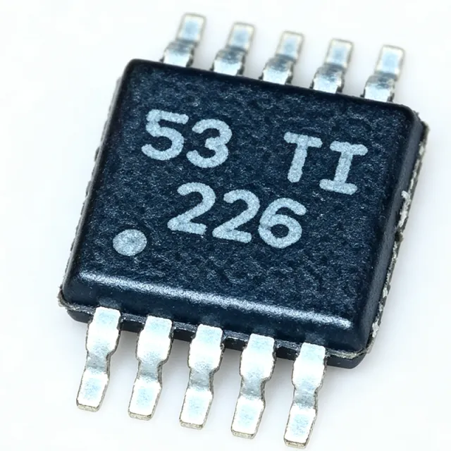
INA226AIDGSR-Q1 - 36V 16-bit I2C Current Monitor AEC-Q100 | TI
MPN: INA226AIDGSR-Q1 ✓ Active| Qty | Unit Price | Extended |
|---|---|---|
| 1 | $2.85 | $2.85 |
| 10 | $2.55 | $25.50 |
| 100 | $2.1 | $210.00 |
| 500 | $1.8 | $900.00 |
| 1,000 | $1.55 | $1,550.00 |
INA226AIDGSR-Q1 Overview
A current shunt and power monitor is a precision analog front-end placed across a series sense resistor; it belongs to the broader hierarchy of current sensing ICs, power management ICs, and semiconductor devices. By digitizing the microvolt-level shunt drop with a 16-bit delta-sigma ADC, it converts raw current into calibrated digital data that microcontrollers can read over I2C.
Key features include a 16-bit ADC resolution for fine measurement granularity, a bus voltage monitoring range up to 36V, bidirectional shunt measurement enabling both charge and discharge tracking, a multi-function ALERT pin, and two address pins (A0, A1) supporting multiple devices on one I2C bus. Automotive AEC-Q100 qualification makes it suitable for vehicle environments.
The architecture pairs a precision front-end with a programmable conversion-time and averaging engine, allowing engineers to trade conversion speed against noise performance. Register-based configuration permits calibration for specific shunt values, so current and power are reported in native units without host-side computation.
Typical applications include automotive battery management systems, server and telecom power rails, solar/MPPT power monitoring, and industrial motor drive current sensing. In battery systems, the bidirectional measurement tracks both charging and discharging current through a single shunt.
Design consideration: shunt resistor selection directly trades measurement resolution against power dissipation; keep the full-scale shunt drop within the input range while minimizing shunt loss at peak load.
Drop-in alternatives for INA226AIDGSR-Q1 — same package, pin-to-pin compatible. Different-package parts requiring PCB rework are excluded.
Variants in this series
Same-series models that are drop-in compatible with INA226AIDGSR-Q1 (same form factor and footprint) — differing in Alert Function, Function, Package.
Quick Comparison Tool — Select alternative parts for side-by-side comparison:
INA226AIDGSR
✓ In Stock
$1.21 / Unit
View Datasheet →INA238QDGSRQ1
📋 Reference alternative (not in catalog)
INA237QDGSRQ1
📋 Reference alternative (not in catalog)
INA228QDGSRQ1
📋 Reference alternative (not in catalog)
INA230AIDGSR
📋 Reference alternative (not in catalog)
INA226AIDGSR-Q1 Maximum Ratings & Electrical Characteristics
| Function | Current, Voltage, and Power Monitor |
| ADC Resolution | 16 bit |
| Bus Voltage Range | 0 V to 36 V |
| Measurement Type | High-side or Low-side, Bidirectional |
| Interface | I2C / SMBus compatible |
| Alert Function | Yes (multi-function ALERT pin) |
| Address Pins | A0, A1 |
| Package | VSSOP-10 (DGS) |
| Mounting Type | Surface Mount |
| Automotive Qualification | AEC-Q100 Qualified |
| RoHS Status | Compliant |
INA226AIDGSR-Q1 Pin Configuration
| Pin 1 | VS — Power supply pin |
| Pin 2 | SDA — I2C data input/output |
| Pin 3 | SCL — I2C clock input |
| Pin 4 | ALERT — Multi-function alert output, open-drain |
| Pin 5 | A0 — Address pin 0 |
| Pin 6 | A1 — Address pin 1 |
| Pin 7 | GND — Ground reference |
| Pin 8 | IN- — Shunt voltage negative input (connects to shunt load side) |
| Pin 9 | IN+ — Shunt voltage positive input (connects to shunt bus side) |
| Pin 10 | VBS — Bus voltage sense input |
Typical Applications
INA226AIDGSR-Q1 is suitable for 6 applications: Automotive Battery Management, Server and Telecom Power Rail Monitoring, Solar and MPPT Power Monitoring, Industrial Motor Drive Current Sensing, Consumer and IoT Device Power Budgeting, Test and Measurement Instrumentation.
Automotive Battery Management
The INA226AIDGSR-Q1's AEC-Q100 qualification and bidirectional 16-bit shunt measurement make it ideal for automotive battery current monitoring. Placed across a low-value shunt in the battery feed, it resolves both charge and discharge current through a single resistor, while its 0V-to-36V bus range covers 12V and 48V automotive rails. The I2C interface with A0/A1 address pins allows multiple monitors on one bus for cell-group or load-point tracking, and the ALERT pin provides overcurrent fault notification to the BMS microcontroller.
Recommended
Server and Telecom Power Rail Monitoring
In servers and telecom rectifiers, the INA226AIDGSR-Q1 provides 16-bit current, voltage, and power telemetry on -48V and intermediate bus rails up to 36V. Its programmable averaging trades conversion speed for noise, enabling stable rack-level power reporting, while the ALERT pin supports fast overcurrent flagging without continuous MCU polling. Multiple devices share one I2C bus via the two address pins, allowing dense per-rail monitoring with a single host controller and minimal board area in the VSSOP-10 package.
Recommended
Solar and MPPT Power Monitoring
Solar charge controllers use the INA226AIDGSR-Q1 to measure panel and battery current simultaneously. The bidirectional shunt input distinguishes charging current from battery discharge, while the 36V bus range covers common 12V/24V PV systems. The 16-bit ADC resolves small current changes needed for MPPT algorithms to track the maximum power point precisely. Its I2C output feeds MPPT microcontrollers directly, and register-based calibration lets designers optimize resolution for their chosen shunt value and expected current range.
Recommended
Industrial Motor Drive Current Sensing
In industrial drives and robotics, the INA226AIDGSR-Q1 monitors DC bus and motor supply current for load diagnostics, stall detection, and energy reporting. High-side placement across a shunt avoids ground disturbance, and the 16-bit resolution detects small load changes signaling mechanical wear. The ALERT pin can flag overcurrent conditions in hardware, faster than software polling. Industrial 24V rails fall comfortably within the 36V bus range, and the VSSOP-10 package fits dense gate-driver boards.
Recommended
Consumer and IoT Device Power Budgeting
Battery-powered IoT devices use the INA226AIDGSR-Q1 to profile current consumption of subsystems, enabling firmware power optimization. The 16-bit ADC resolves microamp-level sleep currents and milliamp-level transmit bursts on the same shunt. Developers place monitors on individual load switches to attribute power per subsystem, reading data over I2C during development and in-field telemetry. The compact VSSOP-10 footprint suits space-constrained wearable and smart-home PCBs, and the commercial INA226AIDGSR grade may be substituted for cost savings in non-automotive builds.
Recommended
Test and Measurement Instrumentation
Bench power supplies, USB power analyzers, and automated test equipment employ the INA226AIDGSR-Q1 as a precision current measurement front-end. Its 16-bit delta-sigma ADC and register-calibrated shunt scaling deliver traceable current readings without precision analog gain stages, reducing BOM cost and calibration drift. The programmable conversion time allows fast transient capture or high-accuracy averaging per test mode. The 36V range covers USB-C VBUS and multi-rail bench outputs, and the I2C interface integrates directly with instrument microcontrollers.
Recommended
Recommended Products Summary
Engineering reference data for INA226AIDGSR-Q1 — comparison, design guidance, and compliance information.
Selection Guide
Comparison with Alternatives
| Parameter | This Product | INA238QDGSRQ1 | INA237QDGSRQ1 | INA228QDGSRQ1 | INA230AIDGSR | INA226AIDGSR |
|---|---|---|---|---|---|---|
| Package | VSSOP-10 (DGS) | VSSOP-10 (DGS) - same | VSSOP-10 (DGS) - same | VSSOP-10 (DGS) - same | VSSOP-10 (DGS) - same | VSSOP-10 (DGS) - same |
| Brand | Texas Instruments | Texas Instruments | Texas Instruments | Texas Instruments | Texas Instruments | Texas Instruments |
| Bus Voltage Range | 0 V to 36 V | 0 V to 85 V | 0 V to 85 V | 0 V to 85 V | 0 V to 36 V | 0 V to 36 V |
| ADC Resolution | 16 bit | 16 bit | 16 bit | 20 bit | 16 bit | 16 bit |
| Automotive Qualification | AEC-Q100 Qualified | AEC-Q100 Qualified | AEC-Q100 Qualified | AEC-Q100 Qualified | No (commercial) | No (commercial) |
| Interface | I2C / SMBus | I2C / SMBus | I2C / SMBus | I2C / SMBus | I2C / SMBus | I2C / SMBus |
| ALERT Pin | Yes | Yes | Yes | Yes | Yes | Yes |
Key Differentiators
- AEC-Q100 automotive qualification (vs INA226AIDGSR)
- Extended 85V bus range in pin-compatible successors (vs INA238QDGSRQ1)
- Higher resolution option available (vs INA228QDGSRQ1)
Design Notes
Use a Kelvin (4-wire) connection from the shunt resistor to the IN+ and IN- pins: route dedicated sense traces directly from the shunt pads rather than sharing power-carrying copper. Any milliohm of trace resistance in series with the sense path creates current-proportional measurement error. Keep the shunt-to-IN+ and IN- traces short, symmetric, and away from switching nodes of adjacent converters.
When migrating from INA226-Q1 to the pin-compatible INA237-Q1/INA238-Q1/INA228-Q1 second sources (per TI E2E guidance), do not assume register defaults are identical - the INA23x/INA228 family uses updated architectures and calibration register maps. Re-verify conversion-time, averaging, and calibration register settings, and re-run full accuracy validation before releasing the swap in production.
Size the shunt resistor to balance resolution against dissipation: a larger shunt improves the signal-to-noise ratio into the 16-bit ADC but increases power loss (P = I^2 x R) at peak load. Keep the full-scale shunt drop within the device input range at maximum current, and choose the conversion time/averaging settings so noise over the selected window meets your accuracy budget for the smallest current you must resolve.
The ALERT pin is an open-drain output - provide a pull-up resistor to the appropriate logic rail and consider wiring it to an MCU interrupt for hardware-speed overcurrent response rather than polling the I2C bus. Add standard I2C pull-ups on SDA/SCL and follow SMBus timing limits if the bus is shared with other automotive devices.
Compliance Information
AEC-Q100 qualified per TI product page. RoHS compliance inferred from TI standard product offering; verify on TI quality portal for certification documentation.







