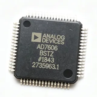
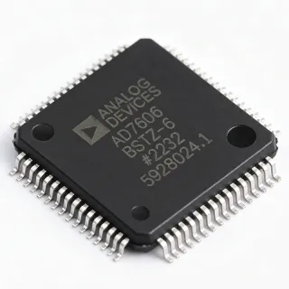
AD7606BSTZ-4 - 16-Bit 4-Ch Simultaneous Sampling ADC | Analog Devices
MPN: AD7606BSTZ-4 ✓ Active| Qty | Unit Price | Extended |
|---|---|---|
| 1 | $18.5 | $18.50 |
| 10 | $16.8 | $168.00 |
| 100 | $14.2 | $1,420.00 |
| 500 | $12.9 | $6,450.00 |
| 1,000 | $11.6 | $11,600.00 |
AD7606BSTZ-4 Overview
A data acquisition system (DAS) is a complete signal chain that conditions, samples, and converts analog signals into digital data for processing. The AD7606BSTZ-4 integrates the entire front-end, eliminating the need for external op-amps, filters, and references, which simplifies design and reduces board space. As a simultaneous sampling ADC, it captures all four channels at the same instant, which is critical for applications requiring phase-accurate measurements across multiple inputs, such as power monitoring and motor control.
Key features include 1 MΩ analog input impedance regardless of sampling frequency, input clamp protection up to ±16.5 V, and a 3 dB cutoff frequency of 22 kHz for the antialiasing filter, providing 40 dB antialias rejection at 200 kSPS. The flexible digital filter is pin-driven, yielding improvements in SNR and reducing the 3 dB bandwidth. The device operates over the industrial temperature range of -40°C to +85°C and is RoHS compliant.
The AD7606BSTZ-4 uses a charge redistribution successive approximation architecture, which offers excellent DC accuracy and low power consumption. The integrated 2.5 V reference and buffer ensure stable conversion results without external components. The device also features a flexible digital filter that can be configured via the oversampling pins to trade off throughput for noise performance, allowing designers to optimize SNR for their specific application.
Typical applications include power line monitoring, protective relays, motor control, and industrial data acquisition systems. The simultaneous sampling capability and high input impedance make it ideal for measuring three-phase voltages and currents with phase accuracy. The wide input range and clamp protection ensure robust operation in harsh industrial environments.
When designing with the AD7606BSTZ-4, ensure that the analog input signals are within the specified ±10 V or ±5 V ranges and that the supply decoupling is adequate. The device requires a clean 5 V supply and proper grounding to achieve the specified performance. The digital interface should be configured according to the host processor's requirements, and the oversampling pins should be set to achieve the desired balance between throughput and noise.
Drop-in alternatives for AD7606BSTZ-4 — same package, pin-to-pin compatible. Different-package parts requiring PCB rework are excluded.
Variants in this series
Same-series models that are drop-in compatible with AD7606BSTZ-4 (same form factor and footprint) — differing in Number of Channels, Input Type, Package, Sampling Rate, Input Voltage Range.
Quick Comparison Tool — Select alternative parts for side-by-side comparison:
AD7606BSTZ-4RL
✅ Drop-In✓ In Stock
$9.55 / Unit
View Datasheet →AD7606BSTZ
✅ Drop-In✓ In Stock
$16.9 / Unit
View Datasheet →AD7606BSTZ-6RL
✅ Drop-In✓ In Stock
$29.8 / Unit
View Datasheet →ADS8588S
✅ Drop-In ⚠️ Specs Unverified📋 Reference alternative (not in catalog)
AD7606C-4
✅ Drop-In ⚠️ Specs Unverified📋 Reference alternative (not in catalog)
AD7606BSTZ-4 Maximum Ratings & Electrical Characteristics
| Resolution | 16 bit |
| Number of Channels | 4 |
| Sampling Rate | 200 kSPS |
| Input Type | Single-Ended |
| Input Voltage Range | ±10 V, ±5 V |
| Interface | DSP, MICROWIRE, Parallel, QSPI, Serial, SPI |
| Supply Voltage | 5 V |
| Analog Input Impedance | 1 MΩ |
| Input Clamp Protection | ±16.5 V |
| Antialiasing Filter 3 dB Cutoff | 22 kHz |
| Antialias Rejection | 40 dB at 200 kSPS |
| Reference | Internal 2.5 V |
| Operating Temperature Range | -40°C to +85°C |
| Package | 64-LQFP (10x10 mm) |
| RoHS | Compliant |
AD7606BSTZ-4 Pin Configuration
| Pin 1 | V1 — Analog input channel 1 |
| Pin 2 | V2 — Analog input channel 2 |
| Pin 3 | V3 — Analog input channel 3 |
| Pin 4 | V4 — Analog input channel 4 |
| Pin 5 | AGND — Analog ground |
| Pin 6 | AVCC — Analog supply voltage (5V) |
| Pin 7 | REFIN/REFOUT — Reference input/output |
| Pin 8 | REFCAP — Reference buffer capacitor |
| Pin 9 | DVCC — Digital supply voltage (5V) |
| Pin 10 | DGND — Digital ground |
| Pin 11 | CS — Chip select (active low) |
| Pin 12 | SCLK — Serial clock input |
| Pin 13 | SDI — Serial data input |
| Pin 14 | SDO — Serial data output |
| Pin 15 | BUSY — Busy output (high during conversion) |
| Pin 16 | RESET — Reset input (active low) |
Typical Applications
AD7606BSTZ-4 is suitable for 6 applications: Power Line Monitoring, Protective Relays, Motor Control, Industrial Data Acquisition, Medical Monitoring, Test and Measurement.
Power Line Monitoring
The AD7606BSTZ-4 is ideal for power line monitoring systems that require simultaneous sampling of multiple voltage and current channels. Its 4-channel configuration matches three-phase systems plus neutral, and the 16-bit resolution with 200 kSPS throughput captures harmonics up to the 40th order. The ±10 V input range directly interfaces with voltage transformers, while the 1 MΩ input impedance minimizes loading. The integrated antialiasing filter and clamp protection ensure robust operation in noisy substation environments, and the SPI interface simplifies connection to a host microcontroller for real-time analysis.
Recommended
Protective Relays
In protective relays, the AD7606BSTZ-4 provides simultaneous sampling of current and voltage signals to detect faults with high accuracy. Its 4 channels can monitor three-phase currents and one voltage, or vice versa, with 16-bit resolution ensuring precise measurement of fault magnitudes. The 200 kSPS sampling rate allows fast detection of transients, while the ±5 V input range matches common relay input modules. The device's integrated reference and buffer reduce external component count, and its industrial temperature range (-40°C to +85°C) ensures reliable operation in harsh substation conditions.
Recommended
Motor Control
The AD7606BSTZ-4 is well-suited for motor control applications that require simultaneous sampling of phase currents and voltages for field-oriented control (FOC). Its 4 channels can capture two phase currents, one DC bus voltage, and one temperature sensor input, all sampled simultaneously to maintain phase alignment. The 16-bit resolution provides high precision for current sensing, and the 200 kSPS throughput supports fast control loops. The device's 1 MΩ input impedance allows direct connection to shunt resistors without additional buffering, and the SPI interface enables easy integration with DSPs or MCUs.
Recommended
Industrial Data Acquisition
For general industrial data acquisition, the AD7606BSTZ-4 offers a compact, integrated solution for capturing multiple analog signals. Its 4 channels can monitor temperature, pressure, flow, and vibration sensors simultaneously, with 16-bit resolution ensuring high accuracy. The ±10 V input range accommodates a wide variety of industrial sensors, and the 1 MΩ input impedance prevents signal loading. The device's integrated antialiasing filter simplifies signal conditioning, and its SPI interface allows easy connection to PLCs or embedded systems. The wide operating temperature range makes it suitable for factory floor environments.
Recommended
Medical Monitoring
The AD7606BSTZ-4 can be used in medical monitoring equipment such as patient monitors and diagnostic devices that require simultaneous sampling of multiple physiological signals. Its 4 channels can capture ECG, EEG, and other biosignals with 16-bit resolution for high fidelity. The device's low input leakage and high input impedance are beneficial for connecting to electrodes without signal degradation. The 200 kSPS sampling rate is sufficient for most biosignal applications, and the small 64-LQFP package saves board space in portable devices. The integrated reference and buffer reduce external components, simplifying design.
Recommended
Test and Measurement
In test and measurement equipment, the AD7606BSTZ-4 provides accurate simultaneous sampling for multi-channel data acquisition. Its 4 channels can capture multiple signals such as voltage, current, and frequency simultaneously, with 16-bit resolution for precise measurements. The 200 kSPS throughput allows capturing fast transients, and the ±10 V input range is compatible with many test signals. The device's integrated antialiasing filter ensures clean measurements, and its SPI interface enables easy integration with FPGAs or microcontrollers. The compact package is ideal for portable instruments.
Recommended
Recommended Products Summary
Engineering reference data for AD7606BSTZ-4 — comparison, design guidance, and compliance information.
Selection Guide
Comparison with Alternatives
| Parameter | This Product | AD7606BSTZ-4RL | AD7606BSTZ | AD7606BSTZ-6 | ADS8588S |
|---|---|---|---|---|---|
| Package | 64-LQFP (10x10 mm) | 64-LQFP (10x10 mm) - same | 64-LQFP (10x10 mm) - same | 64-LQFP (10x10 mm) - same | 64-LQFP (10x10 mm) - same |
| Brand | Analog Devices | Analog Devices | Analog Devices | Analog Devices | Texas Instruments |
| Number of Channels | 4 | 4 | 8 | 6 | 8 |
| Resolution | 16 bit | 16 bit | 16 bit | 16 bit | 16 bit |
| Sampling Rate | 200 kSPS | 200 kSPS | 200 kSPS | 200 kSPS | 200 kSPS |
| Input Voltage Range | ±10 V, ±5 V | ±10 V, ±5 V | ±10 V, ±5 V | ±10 V, ±5 V | ±10 V, ±5 V |
| Interface | SPI, QSPI, MICROWIRE, Parallel, DSP | SPI, QSPI, MICROWIRE, Parallel, DSP | SPI, QSPI, MICROWIRE, Parallel, DSP | SPI, QSPI, MICROWIRE, Parallel, DSP | SPI, Parallel |
| Input Impedance | 1 MΩ | 1 MΩ | 1 MΩ | 1 MΩ | 1 MΩ |
Key Differentiators
- 4-channel simultaneous sampling in a compact 64-LQFP package (vs AD7606BSTZ (8-channel))
- Pin-to-pin compatible with the AD7606 family (vs ADS8588S (Texas Instruments))
- Integrated antialiasing filter and reference (vs ADS8588S)
Design Notes
The AD7606BSTZ-4 requires a clean 5 V analog supply (AVCC) and digital supply (DVCC). Use separate analog and digital grounds to minimize noise coupling. Place 100 nF decoupling capacitors close to each supply pin and a 10 µF bulk capacitor on the AVCC rail. The internal reference requires a 1 µF capacitor on REFCAP for stability.
For optimal performance, keep analog input traces short and shielded from digital signals. Use a solid ground plane under the device and route the SPI lines away from analog inputs. The 64-LQFP package has an exposed pad that should be soldered to the ground plane for thermal and electrical performance. Follow the layout guidelines in the AD7606 datasheet for best results.
Ensure the analog input signals do not exceed the absolute maximum ratings of ±16.5 V, even though the device has internal clamp protection. The input range is set by the RANGE pin; configure it correctly for ±5 V or ±10 V operation. Do not leave the RESET pin floating; tie it high or use a pull-up resistor. The BUSY pin indicates conversion status and should be monitored to avoid reading data during conversion.
Compliance Information
RoHS compliant per Analog Devices product page. Not AEC-Q100 qualified.