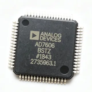
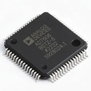
AD7606BSTZ-RL - 16-Bit 8-Ch Simultaneous ADC | Analog Devices
MPN: AD7606BSTZ-RL ✓ Active| Qty | Unit Price | Extended |
|---|---|---|
| 1 | $18.5 | $18.50 |
| 10 | $16.8 | $168.00 |
| 100 | $14.2 | $1,420.00 |
| 500 | $12.9 | $6,450.00 |
| 1,000 | $11.6 | $11,600.00 |
AD7606BSTZ-RL Overview
A data acquisition system (DAS) is a complete signal chain that conditions, samples, and converts analog signals into digital data for processing. The AD7606 integrates the entire front-end, eliminating the need for external op-amps, references, and antialiasing filters, thereby reducing board space and design complexity. As a simultaneous sampling ADC, it captures all channels at the same instant, which is critical for applications requiring phase-accurate measurements across multiple inputs.
Key features include a 200 kSPS throughput rate per channel, 16-bit resolution with no missing codes, and a 2.5 V internal reference with ±1% accuracy. The device offers both serial (SPI/QSPI/MICROWIRE) and parallel interfaces, and supports daisy-chaining for multiple devices. The flexible digital filter can be configured to improve noise performance, and the analog input clamp protects against overvoltage conditions up to ±16.5 V.
The AD7606 uses a charge redistribution SAR architecture, which provides excellent linearity and low power consumption. The integrated antialiasing filter simplifies external filtering requirements, and the track-and-hold amplifier ensures accurate sampling of fast-changing signals. The device operates over the industrial temperature range of -40°C to +85°C and is available in a 64-lead LQFP package.
Typical applications include power line monitoring, protective relays, motor control, and multi-phase energy measurement. The simultaneous sampling capability ensures accurate phase relationships between channels, which is essential for power quality analysis. The device is also suitable for vibration analysis and other multi-channel data acquisition systems.
When designing with the AD7606, ensure that the analog input range is properly configured via the RANGE pin, and that the reference decoupling capacitor is placed close to the REFIN/REFOUT pin. The digital interface should be matched to the host processor's voltage level, and the AVCC and DVCC supplies should be decoupled with 0.1 µF and 10 µF capacitors.
Drop-in alternatives for AD7606BSTZ-RL — same package, pin-to-pin compatible. Different-package parts requiring PCB rework are excluded.
Variants in this series
Same-series models that are drop-in compatible with AD7606BSTZ-RL (same form factor and footprint) — differing in Input Type, Number of Channels, Antialiasing Filter, Input Voltage Range, Resolution.
Quick Comparison Tool — Select alternative parts for side-by-side comparison:
AD7606BSTZ-4RL
✅ Drop-In✓ In Stock
$9.55 / Unit
View Datasheet →AD7606BSTZ-6RL
✅ Drop-In✓ In Stock
$29.8 / Unit
View Datasheet →AD7606BSTZ
✅ Drop-In✓ In Stock
$16.9 / Unit
View Datasheet →ADS8588S
✅ Drop-In ⚠️ Specs Unverified📋 Reference alternative (not in catalog)
GX7606
✅ Drop-In ⚠️ Specs Unverified📋 Reference alternative (not in catalog)
AD7606BSTZ-RL Maximum Ratings & Electrical Characteristics
| Resolution | 16 bit |
| Number of Channels | 8 |
| Sampling Rate | 200 kSPS per channel |
| Input Type | Bipolar, single-ended |
| Input Voltage Range | ±5 V, ±10 V |
| Interface | Parallel, SPI, QSPI, MICROWIRE, DSP |
| Supply Voltage | 5 V (AVCC), 2.3 V to 5 V (VDRIVE) |
| Internal Reference | 2.5 V, ±1% accuracy |
| Analog Input Impedance | 1 MΩ |
| Antialiasing Filter | Second-order |
| Input Clamp Protection | ±16.5 V |
| Operating Temperature Range | -40°C to +85°C |
| Package | 64-LQFP (10x10 mm) |
| Mounting Type | Surface Mount |
| RoHS Status | Compliant |
AD7606BSTZ-RL Pin Configuration
| Pin 1 | AVCC — Analog supply voltage, 5 V |
| Pin 2 | V1 — Analog input channel 1 |
| Pin 3 | V2 — Analog input channel 2 |
| Pin 4 | V3 — Analog input channel 3 |
| Pin 5 | V4 — Analog input channel 4 |
| Pin 6 | V5 — Analog input channel 5 |
| Pin 7 | V6 — Analog input channel 6 |
| Pin 8 | V7 — Analog input channel 7 |
| Pin 9 | V8 — Analog input channel 8 |
| Pin 10 | AGND — Analog ground |
| Pin 11 | RANGE — Input range select: 0 = ±5 V, 1 = ±10 V |
| Pin 12 | REFOUT/REFIN — Reference output/input, 2.5 V |
| Pin 13 | REFGND — Reference ground |
| Pin 14 | DVCC — Digital supply voltage |
| Pin 15 | VDRIVE — Digital interface supply voltage |
| Pin 16 | DGND — Digital ground |
| Pin 17 | CS — Chip select (active low) |
| Pin 18 | SCLK — Serial clock input |
| Pin 19 | DOUTA — Serial data output A |
| Pin 20 | DOUTB — Serial data output B |
| Pin 21 | BUSY — Busy output, indicates conversion in progress |
| Pin 22 | CONVST A — Conversion start A |
| Pin 23 | CONVST B — Conversion start B |
| Pin 24 | RESET — Reset input (active high) |
| Pin 25 | OS0 — Oversampling mode select 0 |
| Pin 26 | OS1 — Oversampling mode select 1 |
| Pin 27 | OS2 — Oversampling mode select 2 |
| Pin 28 | PAR/SER — Parallel/serial interface select |
| Pin 29 | STBY — Standby mode input |
| Pin 30 | DB0 — Parallel data bus bit 0 |
| Pin 31 | DB1 — Parallel data bus bit 1 |
| Pin 32 | DB2 — Parallel data bus bit 2 |
| Pin 33 | DB3 — Parallel data bus bit 3 |
| Pin 34 | DB4 — Parallel data bus bit 4 |
| Pin 35 | DB5 — Parallel data bus bit 5 |
| Pin 36 | DB6 — Parallel data bus bit 6 |
| Pin 37 | DB7 — Parallel data bus bit 7 |
| Pin 38 | DB8 — Parallel data bus bit 8 |
| Pin 39 | DB9 — Parallel data bus bit 9 |
| Pin 40 | DB10 — Parallel data bus bit 10 |
| Pin 41 | DB11 — Parallel data bus bit 11 |
| Pin 42 | DB12 — Parallel data bus bit 12 |
| Pin 43 | DB13 — Parallel data bus bit 13 |
| Pin 44 | DB14 — Parallel data bus bit 14 |
| Pin 45 | DB15 — Parallel data bus bit 15 |
| Pin 46 | RD — Read strobe (active low) |
| Pin 47 | WR — Write strobe (active low) |
| Pin 48 | A0 — Address bit 0 |
| Pin 49 | A1 — Address bit 1 |
| Pin 50 | A2 — Address bit 2 |
| Pin 51 | A3 — Address bit 3 |
| Pin 52 | A4 — Address bit 4 |
| Pin 53 | A5 — Address bit 5 |
| Pin 54 | A6 — Address bit 6 |
| Pin 55 | A7 — Address bit 7 |
| Pin 56 | A8 — Address bit 8 |
| Pin 57 | A9 — Address bit 9 |
| Pin 58 | A10 — Address bit 10 |
| Pin 59 | A11 — Address bit 11 |
| Pin 60 | A12 — Address bit 12 |
| Pin 61 | A13 — Address bit 13 |
| Pin 62 | A14 — Address bit 14 |
| Pin 63 | A15 — Address bit 15 |
| Pin 64 | EP — Exposed pad, connect to ground |
Typical Applications
AD7606BSTZ-RL is suitable for 6 applications: Power Line Monitoring, Motor Control, Multi-Phase Energy Measurement, Protective Relays, Vibration Analysis, Data Acquisition Systems.
Power Line Monitoring
The AD7606BSTZ-RL is ideal for power line monitoring due to its 8-channel simultaneous sampling capability, which ensures accurate phase relationships between voltage and current channels. The 16-bit resolution and 200 kSPS sampling rate allow precise measurement of harmonics and power quality parameters. The integrated antialiasing filter and input clamp protection simplify the front-end design, making it a complete solution for energy metering and power quality analyzers.
Recommended
Motor Control
The AD7606BSTZ-RL is well-suited for motor control applications. Its simultaneous sampling of multiple current and voltage channels enables accurate vector control and protection. The 16-bit resolution and 200 kSPS rate provide sufficient bandwidth for high-speed motor drives. The integrated features reduce component count and design complexity, making it a compact solution for variable frequency drives and servo controllers.
Recommended
Multi-Phase Energy Measurement
The AD7606BSTZ-RL is designed for multi-phase energy measurement, providing simultaneous sampling of all phases to ensure accurate power calculations. The 16-bit resolution and 200 kSPS rate allow precise measurement of energy consumption and power quality. The integrated reference and antialiasing filter reduce external component count, making it ideal for smart meters and energy monitoring systems.
Recommended
Protective Relays
The AD7606BSTZ-RL is suitable for protective relays in power systems, where accurate and simultaneous measurement of voltage and current is critical for fault detection. The 16-bit resolution and 200 kSPS sampling rate provide the speed and accuracy needed for reliable protection. The integrated input clamp protection and antialiasing filter enhance robustness in harsh industrial environments.
Recommended
Vibration Analysis
The AD7606BSTZ-RL can be used in vibration analysis systems, where multiple accelerometer signals need to be sampled simultaneously to analyze structural health or machinery condition. The 16-bit resolution and 200 kSPS rate capture high-frequency vibration signals with good fidelity. The simultaneous sampling ensures accurate phase relationships between channels, which is essential for modal analysis.
Recommended
Data Acquisition Systems
The AD7606BSTZ-RL is a complete data acquisition system (DAS) that integrates the entire signal chain, making it ideal for general-purpose multi-channel data acquisition. The 16-bit resolution and 200 kSPS rate provide high accuracy and speed for a wide range of applications. The flexible digital interface and daisy-chain capability allow easy integration into larger systems.
Recommended
Recommended Products Summary
Engineering reference data for AD7606BSTZ-RL — comparison, design guidance, and compliance information.
Selection Guide
Comparison with Alternatives
| Parameter | This Product | AD7606BSTZ-4RL | AD7606BSTZ-6RL | ADS8588S | GX7606 |
|---|---|---|---|---|---|
| Package | 64-LQFP (10x10 mm) | 64-LQFP (10x10 mm) | 64-LQFP (10x10 mm) | 64-LQFP (10x10 mm) | 64-LQFP (10x10 mm) |
| Brand | Analog Devices | Analog Devices | Analog Devices | Texas Instruments | GXSC |
| Number of Channels | 8 | 4 | 6 | 8 | 8 |
| Sampling Rate | 200 kSPS | 200 kSPS | 200 kSPS | 200 kSPS | 200 kSPS |
| Input Voltage Range | ±5 V, ±10 V | ±5 V, ±10 V | ±5 V, ±10 V | ±5 V, ±10 V | ±5 V, ±10 V |
| Interface | Parallel, SPI, QSPI, MICROWIRE | Parallel, SPI, QSPI, MICROWIRE | Parallel, SPI, QSPI, MICROWIRE | Parallel, SPI | Parallel, SPI |
| Internal Reference | 2.5 V | 2.5 V | 2.5 V | 2.5 V | 2.5 V |
| Supply Voltage | 5 V (AVCC), 2.3-5 V (VDRIVE) | 5 V (AVCC), 2.3-5 V (VDRIVE) | 5 V (AVCC), 2.3-5 V (VDRIVE) | 5 V (AVCC), 2.3-5 V (VDRIVE) | 5 V (AVCC), 2.3-5 V (VDRIVE) |
Key Differentiators
- 8-channel simultaneous sampling (vs AD7606BSTZ-4RL)
- Pin-to-pin compatible with TI ADS8588S (vs ADS8588S)
- Integrated analog input clamp protection (vs GX7606)
Design Notes
The AD7606BSTZ-RL requires a clean 5 V analog supply (AVCC) and a separate digital supply (VDRIVE) from 2.3 V to 5 V. Decouple AVCC and DVCC with 0.1 µF and 10 µF capacitors placed close to the pins. The internal reference (REFOUT/REFIN) should be decoupled with a 1 µF capacitor to ground to ensure stability and low noise.
Place the AD7606BSTZ-RL on a PCB with a solid ground plane. The exposed pad (EP) must be soldered to the ground plane for proper thermal and electrical performance. Keep analog and digital grounds separate and connect them at a single point. Route analog inputs away from digital traces to minimize noise coupling.
Ensure the RANGE pin is set correctly for the desired input voltage range (±5 V or ±10 V). Incorrect setting can lead to clipping or damage. Also, the CONVST A and CONVST B pins must be triggered simultaneously for true simultaneous sampling. Avoid floating unused digital inputs; tie them to appropriate logic levels.
Compliance Information
RoHS compliant per Analog Devices product page. Not AEC-Q100 qualified. REACH compliance assumed based on ADI policy.