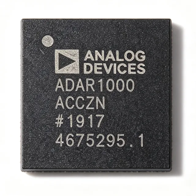
ADAR1000ACCZN-R7 - 8-16GHz 4-Ch X/Ku Beamformer | Analog Devices
MPN: ADAR1000ACCZN-R7 ✓ Active| Qty | Unit Price | Extended |
|---|---|---|
| 1 | $0 | $0.00 |
| 10 | $0 | $0.00 |
| 100 | $0 | $0.00 |
| 500 | $0 | $0.00 |
| 1,000 | $0 | $0.00 |
ADAR1000ACCZN-R7 Overview
A beamformer core chip is an RF integrated circuit that provides independent amplitude and phase control per channel, enabling electronic steering of a phased array antenna without mechanical movement. Within the RF signal chain hierarchy, the ADAR1000 sits between the transceiver and the antenna elements, functioning as the vector-modulating T/R module that shapes the beam. Beamformers like the ADAR1000 are foundational building blocks of modern active electronically scanned array (AESA) architectures used in radar and communication systems.
Key features include 4 fully independent receive and transmit channels covering 8 GHz to 16 GHz, half-duplex operation with fast transmit/receive switching controlled by a single pin, and per-channel programmable phase and gain. The device integrates the complete beamforming function - low noise amplification in receive mode, power amplification in transmit mode, and vector modulation on every channel - reducing board area and component count dramatically versus discrete implementations.
Architecturally, in receive mode input signals pass through the four receive channels and are combined at the common RF_IO pin; in transmit mode the RF_IO input signal is split and passes through the four transmit channels. All on-chip registers are controlled through a simple 4-wire serial port interface (SPI), and two address pins allow SPI control of up to four ADAR1000 devices on the same serial lines, simplifying large array designs. Dedicated transmit and receive load pins provide synchronization of all ADAR1000 chips in the same array.
Typical applications include X-band and Ku-band phased array radar, satellite communication terminals, and multi-beam antenna systems where compact size, precise phase/gain control, and channel-to-channel synchronization are required.
Design consideration: because the four channels share the common RF_IO port, PCB symmetry between channels is important for maintaining amplitude and phase tracking across the array.
This page synthesizes distributor availability data, packaging details, and application guidance not consolidated in the manufacturer datasheet alone.
Drop-in alternatives for ADAR1000ACCZN-R7 — same package, pin-to-pin compatible. Different-package parts requiring PCB rework are excluded.
Quick Comparison Tool — Select alternative parts for side-by-side comparison:
ADAR1000ACCZN
✓ In Stock
$1638.6364 / Unit
View Datasheet →ADAR1000ACCZN-R7 Specifications
| Function | 4-Channel X Band and Ku Band Beamformer Core Chip |
| Frequency Range | 8 GHz to 16 GHz |
| Number of Channels | 4 |
| Operating Mode | Half-duplex (T/R switching) |
| Phase/Gain Control | Per-channel programmable via SPI |
| Control Interface | 4-wire SPI serial port |
| Device Addressing | 2 address pins, up to 4 devices on same serial lines |
| Synchronization | Dedicated TX and RX load pins |
| T/R Switching | Single-pin controlled fast switching |
| Package | 88-pin LGA with exposed pad |
| Mounting Type | Surface Mount |
| Packaging | Tape & Reel (R7) |
ADAR1000ACCZN-R7 88-pin lga with exposed pad Pin Configuration Guide
Pin configuration for ADAR1000ACCZN-R7 (88-pin lga with exposed pad package). Pin numbering, functions, and connection diagrams are defined in the manufacturer datasheet. Refer to it for the exact footprint and soldering guidelines.

No detailed pinout data available for ADAR1000ACCZN-R7.
Refer to the datasheet for full pin configuration.
Typical Applications
ADAR1000ACCZN-R7 is suitable for 6 applications: X-Band Phased Array Radar, Ku-Band Satellite Communication Terminals, Multi-Channel Radar Transceiver Tiles, Electronic Warfare and Direction-Finding Systems, Weather Radar Systems, Multi-Beam Communication Antennas.
X-Band Phased Array Radar
The ADAR1000ACCZN-R7 fits X-band phased array radar directly: its 8 GHz to 16 GHz coverage includes the core X-band radar allocations, and its four independent channels each provide per-channel programmable phase and gain for electronic beam steering. In a typical radar tile, each ADAR1000 drives four radiating elements, with the common RF_IO port connecting to the tile transceiver. Receive-mode signals from the elements are amplified, phase-shifted and combined at RF_IO, while transmit-mode signals are split and routed to the elements. Dedicated load pins synchronize all chips in the array so that every element switches and updates phase states coherently, which is essential for sidelobe control and beam pointing accuracy. Two address pins allow up to four devices on one SPI bus, reducing control routing in dense arrays.
Recommended
Ku-Band Satellite Communication Terminals
For Ku-band satcom terminals, the ADAR1000ACCZN-R7 provides the upper half of its 8 GHz to 16 GHz range, matching Ku-band uplink and downlink allocations. Its half-duplex architecture aligns naturally with TDD-style terminal operation: a single pin controls fast switching between transmit and receive modes, so the same four channels serve both directions without duplicated hardware. Per-channel vector modulation enables precise amplitude tapering and phase progression across the terminal aperture, improving EIRP control and receive sensitivity while suppressing sidelobes toward adjacent satellites. The SPI interface with device addressing allows a terminal controller to manage multiple ADAR1000 chips on shared serial lines, and the 88-pin LGA exposed-pad package keeps the RF front-end compact enough for man-portable and vehicle-mounted terminals.
Recommended
Multi-Channel Radar Transceiver Tiles
Modern AESA radars are built from repeated transceiver tiles, and the ADAR1000ACCZN-R7 is designed precisely as the tile-level beamforming core. Each chip integrates the complete per-channel signal chain - amplification, vector phase/gain control, and T/R switching - for four elements, replacing dozens of discrete components per tile. This integration improves channel-to-channel amplitude and phase tracking, which directly determines beam sidelobe performance. The common RF_IO architecture simplifies tile-to-transceiver routing to a single interface port per chip. Dedicated transmit and receive load pins provide deterministic, array-wide state synchronization, and the SPI register map supports stored beam tables that can be recalled rapidly for fast beam steering. The exposed-pad LGA package bonds to the tile ground plane for RF and thermal performance.
Recommended
Electronic Warfare and Direction-Finding Systems
Electronic warfare receivers benefit from the ADAR1000ACCZN-R7's ability to independently phase- and amplitude-weight four antenna channels across the full 8 GHz to 16 GHz band. In direction-finding applications, controlled inter-channel phase offsets implement interferometric or amplitude-comparison DF techniques with programmable precision, while the receive gain control supports dynamic-range management in dense signal environments. The half-duplex T/R architecture also supports responsive jamming functions where the same aperture is reused for transmit. SPI control allows rapid switching of pre-computed phase/gain states, and multi-device synchronization via the load pins keeps wide-aperture systems coherent. The compact 88-pin LGA exposed-pad package suits conformal and platform-mounted EW arrays where volume and weight are tightly constrained.
Recommended
Weather Radar Systems
X-band weather radar is a classic application for the ADAR1000ACCZN-R7, whose 8 GHz to 16 GHz coverage embraces standard X-band meteorological allocations. Solid-state weather radars use phased arrays to steer the beam electronically, enabling rapid volumetric scanning without a mechanically rotating pedestal. The ADAR1000 supplies the per-element phase and amplitude weighting needed to form and steer the beam and to apply aperture tapering that suppresses ground clutter sidelobes. Its four channels per chip scale economically to the 32-256 element apertures typical of weather radar, with the two address pins and load-pin synchronization keeping large arrays manageable on shared SPI control. The device operates half-duplex, matching the pulsed transmit/receive cycle of weather radar waveforms.
Recommended
Multi-Beam Communication Antennas
Multi-beam and switched-beam communication antennas use the ADAR1000ACCZN-R7 to synthesize multiple simultaneous or rapidly reconfigured beams across 8 GHz to 16 GHz. Because each of the four channels carries independent, SPI-programmable phase and gain, arrays of ADAR1000 devices can form distinct beam weights for different users or satellite slots on a shared aperture. The fast, single-pin T/R switching supports time-division communication protocols, while stored SPI beam tables enable near-instant beam hops. Channel integration within one chip improves amplitude and phase consistency between beams, reducing calibration burden. The 88-pin LGA exposed-pad package and tape-and-reel (-R7) supply format support automated assembly of high-volume commercial terminal and gateway hardware, with two address pins simplifying controller-to-array wiring.
Recommended
Engineering reference data for ADAR1000ACCZN-R7 — comparison, design guidance, and compliance information.
Selection Guide
Comparison with Alternatives
| Parameter | This Product | ADAR1000ACCZN |
|---|---|---|
| Package | 88-pin LGA with exposed pad | 88-pin LGA with exposed pad - same |
| Brand | Analog Devices | Analog Devices |
| Frequency Range | 8 GHz to 16 GHz | 8 GHz to 16 GHz |
| Channels | 4 | 4 |
| Operating Mode | Half-duplex T/R | Half-duplex T/R |
| Control Interface | 4-wire SPI, 2 address pins (up to 4 devices) | 4-wire SPI, 2 address pins (up to 4 devices) |
| Packaging Format | Tape & Reel (-R7) | Tray |
Key Differentiators
- Tape-and-reel supply for automated production (vs ADAR1000ACCZN)
- Four integrated T/R channels per chip (vs Discrete vector modulator + LNA + PA solutions)
- Multi-chip array control (vs ADAR1000ACCZN (same feature set))
Design Notes
The ADAR1000's 88-pin LGA exposed pad must be connected to a continuous, well-stitched ground plane. Design the land pattern per the package outline drawing in the Analog Devices datasheet, with via fencing around the RF transmission lines to the four channel ports and the common RF_IO port. Maintain symmetrical routing from the chip to the four antenna elements so that channel-to-channel amplitude and phase tracking is preserved - asymmetry directly degrades beam sidelobe performance in the array.
The beamformer integrates LNAs, PAs and vector modulators, so supply distribution must handle the aggregate current of four active channels. Consult the Analog Devices datasheet for per-supply pin current ratings and recommended decoupling networks, and place low-ESR decoupling capacitors at each supply pin. Verify total power dissipation in transmit mode against the exposed-pad thermal resistance to keep the junction within the rated operating temperature range.
Use the dedicated transmit and receive load pins to latch phase/gain states across all ADAR1000 chips simultaneously; updating registers over SPI without using the load pins causes channels to update at different times, producing momentary beam distortion during switching. Also configure the two address pins correctly before bringing up the SPI bus - a conflict between two devices with the same address on shared serial lines will corrupt register writes in multi-chip arrays.
Compliance Information
Compliance data not present in the provided web data; verify RoHS/REACH status on the Analog Devices product page for the ADAR1000.