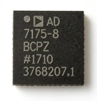
ADAU1979WBCPZ-RL - Quad 24-bit 192kHz Audio ADC, AEC-Q100 | ADI
MPN: ADAU1979WBCPZ-RL ✓ Active| Qty | Unit Price | Extended |
|---|---|---|
| 1 | $7.86 | $7.86 |
| 10 | $7.07 | $70.70 |
| 100 | $6.29 | $629.00 |
| 500 | $5.66 | $2,830.00 |
| 1,000 | $5.03 | $5,030.00 |
ADAU1979WBCPZ-RL Overview
An audio ADC (analog-to-digital converter) is a precision mixed-signal IC that converts continuous-time analog audio signals into discrete digital sample streams for downstream DSP, mixing, or transmission. Within the broader signal-chain taxonomy, the ADAU1979 sits at the analog front-end boundary: audio ADC -> audio codec -> audio DSP -> amplifier, with this particular part optimized for high-performance multi-channel automotive audio capture.
The ADAU1979WBCPZ-RL supports sample rates from 8 kHz to 192 kHz and provides a selectable digital high-pass filter to remove DC offsets. Output data formats include right-justified, left-justified, I²S, and TDM, supporting both master and slave operation modes. An I²C/SPI-compatible control port allows a microcontroller to adjust volume, mute, PGA gain, and many other parameters via software, while a clickless software mute and autoramp function minimize audible pops during gain transitions.
Typical applications include automotive head-unit audio signal acquisition, active noise cancellation (ANC) microphone arrays, infotainment systems, and professional multi-channel audio interfaces. The wide 4.5 V rms input range (vs the more common 1-2 V rms) lets it accept line-level sources directly without external attenuation, simplifying the analog front-end BOM. AEC-Q100 qualification suits it to the harsh electrical and thermal environment of an automotive ECU.
When designing with this IC, decouple each AVDDx pin to its nearest AGNDx pin with a 100 nF ceramic capacitor placed as near the pin as possible, and provide at least one bulk aluminum electrolytic capacitor of ≥10 µF on the PCB. The internal PGA gain and digital volume controls can be cascaded for an effective gain range of more than 80 dB - design the gain plan to keep peak input below 4.5 V rms to avoid clipping.
This page synthesizes distributor pricing, AEC-Q100-qualified drop-in references, and practical decoupling guidance not consolidated in the manufacturer datasheet, giving engineers a single source of comparison.
Drop-in alternatives for ADAU1979WBCPZ-RL — same package, pin-to-pin compatible. Different-package parts requiring PCB rework are excluded.
Variants in this series
Same-series models that are drop-in compatible with ADAU1979WBCPZ-RL (same form factor and footprint) — differing in Architecture, Control Interface, Digital Volume Control, Package.
Quick Comparison Tool — Select alternative parts for side-by-side comparison:
ADAU1979WBCPZ
✅ Drop-In📋 Reference alternative (not in catalog)
ADAU1979WBCPZ-R7
✅ Drop-In📋 Reference alternative (not in catalog)
ADAU1977WBCPZ
✅ Drop-In📋 Reference alternative (not in catalog)
ADAU1978WBCPZ
✅ Drop-In✓ In Stock
$3.95 / Unit
View Datasheet →ADAU1979WBCPZ-RL Maximum Ratings & Electrical Characteristics
| Product Type | Audio ADC (Quad Analog-to-Digital Converter) |
| Number of Channels | 4 |
| Resolution | 24 bit |
| Sample Rate Range | 8 kHz to 192 kHz |
| Input Level | 4.5 V rms (ac-coupled, differential inputs) |
| Architecture | Multibit Sigma-Delta (Σ-Δ) with continuous-time front end |
| Control Interface | I²C / SPI |
| Digital Audio Output Formats | I²S, Left-Justified, TDM |
| Master/Slave Modes | Both supported |
| Digital Volume Control | Yes, with autoramp function |
| Clickless Mute | Yes (software-controllable) |
| Selectable Digital HPF | Yes |
| Supply Voltage | 3.3 V (single supply) |
| Package | 40-LFCSP-WQ (6x6 mm) |
| Automotive Qualification | AEC-Q100 qualified |
| MSL Level | 3 (168 hours) |
| Mounting Type | Surface Mount |
| RoHS Status | ROHS3 Compliant |
ADAU1979WBCPZ-RL Pin Configuration
| Pin 1 | INL1+ — Left channel 1 positive differential input |
| Pin 2 | INL1- — Left channel 1 negative differential input |
| Pin 3 | VDD — 3.3V digital supply |
| Pin 4 | GND — Digital ground |
| Pin 5 | AVDD1 — Analog supply for ADC 1 - decouple with 100nF to AGND1 |
| Pin 6 | AGND1 — Analog ground reference for ADC 1 |
| Pin 7 | VREF — Internal reference voltage decoupling node |
| Pin 8 | FILT+ — Reference filter capacitor positive terminal |
| Pin 9 | FILT- — Reference filter capacitor negative terminal |
| Pin 10 | INL2+ — Left channel 2 positive differential input |
| Pin 11 | INL2- — Left channel 2 negative differential input |
| Pin 12 | AVDD2 — Analog supply for ADC 2 - decouple with 100nF to AGND2 |
| Pin 13 | AGND2 — Analog ground reference for ADC 2 |
| Pin 14 | INL3+ — Left channel 3 positive differential input |
| Pin 15 | INL3- — Left channel 3 negative differential input |
| Pin 16 | AVDD3 — Analog supply for ADC 3 - decouple with 100nF to AGND3 |
| Pin 17 | AGND3 — Analog ground reference for ADC 3 |
| Pin 18 | INL4+ — Left channel 4 positive differential input |
| Pin 19 | INL4- — Left channel 4 negative differential input |
| Pin 20 | AVDD4 — Analog supply for ADC 4 - decouple with 100nF to AGND4 |
| Pin 21 | AGND4 — Analog ground reference for ADC 4 |
| Pin 22 | MCLK — Master clock input (e.g., 12.288 MHz for 48 kHz Fs) |
| Pin 23 | BCLK — Bit clock for serial audio output (master or slave) |
| Pin 24 | LRCLK — Word clock / frame sync for serial audio output |
| Pin 25 | SDATA — Serial audio data output |
| Pin 26 | SCLK — Serial control clock (I²C SCL / SPI SCLK) |
| Pin 27 | SDIO — Serial control data (I²C SDA / SPI MOSI) |
| Pin 28 | SDA_IN — SPI MISO / I²C address input |
| Pin 29 | I2S/SPI — Control interface mode select strap |
| Pin 30 | ADDR0 — I²C address bit 0 strap |
| Pin 31 | ADDR1 — I²C address bit 1 strap |
| Pin 32 | RESET — Active-low hardware reset |
| Pin 33 | PDN — Active-low power-down input |
| Pin 34 | MUTE — Hardware mute input (alternative to software mute) |
| Pin 35 | GPIO0 — General-purpose I/O / interrupt output |
| Pin 36 | GPIO1 — General-purpose I/O |
| Pin 37 | AVDD5 — Analog supply for PLL/bias - decouple with 100nF to AGND5 |
| Pin 38 | AGND5 — Analog ground for PLL/bias |
| Pin 39 | VDD_IO — Digital I/O supply (1.8V to 3.3V) |
| Pin 40 | EPAD — Exposed thermal pad - must be soldered to AGND plane for thermal dissipation |
Typical Applications
ADAU1979WBCPZ-RL is suitable for 6 applications: Automotive Head-Unit Audio Capture, Active Noise Cancellation (ANC) Microphone Array, Automotive Infotainment Line Input, Multi-Channel Professional Audio Interface, Automotive Telematics & Hands-Free Microphone, Industrial Multi-Channel Sensor Acquisition.
Automotive Head-Unit Audio Capture
The ADAU1979WBCPZ-RL is a primary fit for automotive head-unit audio signal acquisition, where 4 channels of 24-bit 192 kHz conversion with AEC-Q100 qualification are required. Its 4.5 V rms input range handles line-level sources (headphone, aux, Bluetooth return) directly without external attenuation, while the on-chip PGA and digital volume per channel replace external op-amp stages. According to the Analog Devices datasheet, the continuous-time Σ-Δ front end minimizes EMI - critical when the part sits next to switching power and RF circuits in an automotive ECU. The 40-LFCSP-WQ package and -40 to +125 C operating range support under-dash mounting.
Recommended
Active Noise Cancellation (ANC) Microphone Array
For in-cabin active noise cancellation, the ADAU1979WBCPZ-RL captures 4 microphone channels simultaneously at up to 48 kHz with phase-aligned sampling. The TDM output mode streams all four channels on a single data line, freeing DSP pins for additional sensors, and the selectable HPF removes wind and DC mic bias offsets without an external capacitor. Its 4.5 V rms input range and 100 dB+ SNR (typical) provide ample dynamic range for cabin-noise mics with high SPL transients per the Analog Devices datasheet, and AEC-Q100 qualification matches the automotive cabin environment.
Recommended
Automotive Infotainment Line Input
The ADAU1979WBCPZ-RL digitizes 4 line inputs on an automotive infotainment main board, supporting AM/FM tuner, CD changer, USB audio, and aux-in sources simultaneously. I²S/TDM output routes all sources to a host DSP for mixing, while I²C control lets the head-unit microcontroller mute, balance, and adjust volume cleanly via the on-chip autoramp and clickless mute functions. The 3.3 V single supply matches infotainment SoC rails and the AEC-Q100 grade handles cranking transients and thermal stress under the dashboard per the Analog Devices datasheet.
Recommended
Multi-Channel Professional Audio Interface
In a 4-channel USB audio interface or studio mixer, the ADAU1979WBCPZ-RL delivers 24-bit / 192 kHz conversion from 4 balanced line inputs simultaneously. Its 4.5 V rms input headroom handles +24 dBu pro-audio levels with margin, eliminating external pad networks, while the high PSRR (>80 dB at 1 kHz typical) rejects USB-bus noise on the analog supply. The Analog Devices datasheet notes the part can synchronize to an external master clock for low-jitter studio operation, and its autoramp gain control is software-programmable via SPI for motorized fader feedback systems.
Recommended
Automotive Telematics & Hands-Free Microphone
For hands-free Bluetooth telephony and in-cabin voice recognition, the ADAU1979WBCPZ-RL captures 4 beamforming microphone channels at 16 kHz (telephony) or 48 kHz (voice recognition). The continuous-time Σ-Δ front end rejects GSM/LTE cellular band noise common in automotive cabins, while the on-chip HPF removes low-frequency rumble and DC mic bias. Per the Analog Devices datasheet, AEC-Q100 qualification and 3.3 V operation suit it to the constrained telematics control unit (TCU) power budget and thermal envelope.
Recommended
Industrial Multi-Channel Sensor Acquisition
Beyond audio, the ADAU1979WBCPZ-RL can digitize 4 industrial vibration or acoustic emission sensors on a single PCB, leveraging its 24-bit resolution and 192 kHz maximum sample rate for ultrasonic vibration analysis. The autoramp PGA accepts sensor outputs from millivolts to several volts without manual gain switching, and the I²C/SPI control port allows remote gain adjustment from an industrial PLC. While not the datasheet's primary use case, the analog performance and 40-LFCSP-WQ footprint suit it to compact industrial condition-monitoring systems.
Recommended
Recommended Products Summary
Engineering reference data for ADAU1979WBCPZ-RL — comparison, design guidance, and compliance information.
Selection Guide
Comparison with Alternatives
| Parameter | This Product | ADAU1979WBCPZ | ADAU1979WBCPZ-R7 | ADAU1977WBCPZ | ADAU1978WBCPZ |
|---|---|---|---|---|---|
| Brand | Analog Devices | Analog Devices | Analog Devices | Analog Devices | Analog Devices |
| Package | 40-LFCSP-WQ (6x6 mm) | 40-LFCSP-WQ (6x6 mm) - same | 40-LFCSP-WQ (6x6 mm) - same | 40-LFCSP-WQ (6x6 mm) - same | 40-LFCSP-WQ (6x6 mm) - same |
| Channels | 4 | 4 | 4 | 4 | 4 |
| Resolution | 24-bit | 24-bit | 24-bit | 24-bit | 24-bit |
| Max Sample Rate | 192 kHz | 192 kHz | 192 kHz | 192 kHz | 192 kHz |
| Input Level | 4.5 V rms | 4.5 V rms | 4.5 V rms | 4.5 V rms | 4.5 V rms |
| Control Interface | I²C / SPI | I²C / SPI | I²C / SPI | I²C / SPI | I²C / SPI |
| TDM Output Support | Yes | Yes | Yes | No | Yes |
| Automotive Grade (AEC-Q100) | Yes | Yes | Yes | Yes | Yes |
| Supply Voltage | 3.3 V | 3.3 V | 3.3 V | 3.3 V | 3.3 V |
Key Differentiators
- Direct 4.5 V rms input without external attenuation (vs PCM1863 (Texas Instruments))
- AEC-Q100 automotive qualification integrated (vs ADAU1962A (Analog Devices))
- On-chip PGA + digital volume per channel (vs PCM1864 (Texas Instruments))
- Continuous-time sigma-delta front end for low EMI (vs Discrete sigma-delta ADCs with switched-capacitor input)
Design Notes
The ADAU1979WBCPZ-RL requires a single 3.3 V supply but has 5 separate analog supply pins (AVDD1-5) plus VDD and VDD_IO that must each be decoupled to their nearest AGND pin with a 100 nF ceramic capacitor placed as close to the IC as physically possible. Add a bulk aluminum electrolytic capacitor of at least 10 uF on the same PCB near the part. The Analog Devices datasheet emphasizes that a clean analog supply is critical for THD+N performance - place a ferrite bead between the 3.3V digital and analog rails if they share an upstream regulator.
The 40-LFCSP-WQ (6x6 mm) package has a center exposed thermal pad (EPAD) that MUST be soldered to the AGND plane for both thermal dissipation and electrical ground reference. Thermal vias on a 1.2 mm pitch grid under the EPAD are strongly recommended to keep junction temperature within the automotive -40 to +125 C range. Per the Analog Devices datasheet, missing or partial EPAD soldering can degrade PSRR by 10+ dB and cause thermal shutdown under load.
Do not exceed 4.5 V rms on any analog input or the input PGA will clip and distort - design the gain plan to keep peak input below this limit with 6 dB of headroom for transients. The MCLK frequency must be selected from the supported master clock ratios in the datasheet (e.g., 256 x Fs for 48 kHz = 12.288 MHz, or 384 x Fs = 18.432 MHz). Using an unsupported MCLK ratio causes the PLL to fail to lock and the ADC outputs invalid data. Verify lock via the GPIO interrupt register readback before enabling audio output.
Route the analog differential input traces (INL1+, INL1-, etc.) as matched-length 100 ohm differential pairs from the connector to the IC pins, with a continuous ground plane underneath and no other signal traces crossing them. Keep digital audio traces (BCLK, LRCLK, SDATA) on the opposite side of the PCB or shielded by ground to prevent coupling into the high-impedance analog inputs. Per the Analog Devices datasheet, the continuous-time sigma-delta front end tolerates moderate digital noise but degrades to 80 dB THD+N under worst-case coupling.
Compliance Information
ROHS3 Compliant and REACH Unaffected per partgenie.ai product analysis (2026-10-06). AEC-Q100 qualified for automotive applications. MSL 3 (168 hours) moisture sensitivity per the manufacturer datasheet.