AIMW120R035M1H - 1200V 35mΩ SiC MOSFET | Infineon | Automotive
MPN: AIMW120R035M1H ✓ Active| Qty | Unit Price | Extended |
|---|---|---|
| 1 | $18.5 | $18.50 |
| 10 | $16.8 | $168.00 |
| 100 | $14.9 | $1,490.00 |
| 500 | $13.2 | $6,600.00 |
| 1,000 | $11.9 | $11,900.00 |
AIMW120R035M1H Overview
A silicon carbide MOSFET is a unipolar power semiconductor switch that uses a wide-bandgap SiC semiconductor layer instead of conventional silicon. Because SiC offers roughly ten times higher critical electric field strength, the drift region can be made much thinner and more heavily doped, yielding lower specific on-resistance, lower switching losses, and far higher junction temperature capability than comparable silicon superjunction or IGBT devices. Within the power semiconductor hierarchy, the AIMW120R035M1H sits under power MOSFETs, discrete semiconductors, and power conversion components.
Key differentiating specifications include the 1200 V maximum drain-source voltage, the 35 mOhm typical on-state resistance at 25C, and the 52 A continuous drain current rating at 25C. The trench-gate CoolSiC cell design provides a highly reliable gate oxide and supports the negative gate-source voltage turn-off margins demanded by automotive designs, while the wide bandgap material enables low gate charge and fast, clean switching transitions.
Technically, the CoolSiC trench architecture couples a deep trench gate with an optimized cell pitch to reduce channel resistance, which is the dominant resistance term in medium-voltage SiC MOSFETs. Infineon explicitly recommends operating conditions that do not exceed 80% of the datasheet maximum ratings for optimum lifetime and reliability, a derating guideline documented in the datasheet maximum-ratings section.
Typical applications include onboard chargers (OBC) and DC-DC converters in electric vehicles, traction inverters auxiliary supplies, solar string inverters, and industrial motor drives operating from 800V-class DC buses. The 1200 V blocking capability with 35 mOhm on-resistance makes the device a strong fit for half-bridge and boost topologies switching at 50-150 kHz.
A key design consideration is gate-drive engineering: fast SiC switching produces high dv/dt, so designers should minimize common-source inductance, use negative gate drive for reliable turn-off, and verify thermal design against the 80% derating recommendation for maximum ratings.
This page synthesizes verified datasheet parameters, drop-in alternatives, pricing tiers, and practical design guidance not found in the manufacturer datasheet alone. Pricing data referenced on this page is as of 2026-09-11.
Drop-in alternatives for AIMW120R035M1H — same package, pin-to-pin compatible. Different-package parts requiring PCB rework are excluded.
Quick Comparison Tool — Select alternative parts for side-by-side comparison:
IMW120R035M1H
✅ Drop-In ⚠️ 参数待验证📋 Reference alternative (not in catalog)
AIMW120R035M1HXKSA1
✅ Drop-In📋 Reference alternative (not in catalog)
AIMW120R035M1H Maximum Ratings & Electrical Characteristics
| Technology | CoolSiC G1 SiC Trench MOSFET |
| Drain-Source Voltage VDS | 1200 V |
| On-State Resistance RDS(on) | 35 mOhm at Tj = 25C |
| Continuous Drain Current ID | 52 A at 25C |
| Qualification | Automotive (AEC-grade per Infineon automotive CoolSiC program) |
| Package | TO-247 |
| Polarity | N-Channel |
| Generation | 1200V G1 (first generation) |
| Mounting Type | Through-Hole |
| Recommended Operating Derating | Do not exceed 80% of maximum ratings (per datasheet) |
AIMW120R035M1H to-247 Pin Configuration Guide
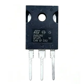
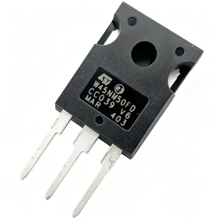
Pin configuration for AIMW120R035M1H (to-247 package). This power device features gate, drain, and source terminals. For non-polarized packages, refer to the manufacturer datasheet for exact pin 1 orientation and footprint details. Common applications include power supply design, motor driving, and load switching.

No detailed pinout data available for AIMW120R035M1H.
Refer to the datasheet for full pin configuration.
Typical Applications
AIMW120R035M1H is suitable for 6 applications: EV Onboard Charger (OBC), Automotive HV DC-DC Converter, Solar String Inverter Boost Stage, Industrial Motor Drive Inverter, Fast EV Charging Infrastructure, High-Voltage Test and Laboratory Power Supplies.
EV Onboard Charger (OBC)
Electric-vehicle onboard chargers convert the AC grid to a high-voltage DC battery bus, typically through a PFC front end followed by an isolated LLC or CLLC stage running from 400-800 V links. The AIMW120R035M1H fits this application because its 1200 V blocking voltage covers 800 V-class battery systems with margin, while its 35 mOhm on-resistance at 25C keeps conduction losses low at the 20-40 A RMS levels typical of 7-22 kW chargers. In the LLC bridge legs, switching at 100-300 kHz with zero-voltage switching, the SiC trench device's low output charge and fast switching sharply reduce magnetics size versus IGBT solutions. Infineon recommends keeping operation within 80% of maximum ratings, so designers should target bus and peak currents accordingly and validate hot RDS(on) for thermal sizing.
Recommended
Automotive HV DC-DC Converter
High-voltage auxiliary DC-DC converters in EVs step the 400-800 V traction battery down to the 12 V or 48 V board net, and often run full-bridge or LLC topologies at high switching frequency to minimize transformer size. The AIMW120R035M1H is well suited because the automotive-qualified 1200 V CoolSiC die withstands the traction bus plus transients, and 52 A at 25C current capability covers primary-side peak currents in 3-5 kW converters. The G1 trench technology's low gate charge reduces driver loss at 100-200 kHz switching frequencies, improving overall efficiency above 95%. Because automotive environments impose wide temperature and vibration ranges, apply Infineon's 80% maximum-rating derating guideline and verify junction temperature against the datasheet thermal resistance with realistic cold-plate or heatsink conditions.
Recommended
Solar String Inverter Boost Stage
Grid-tied solar string inverters boost the panel input from roughly 200-850 V up to a stable 700-850 V DC link using interleaved boost stages that switch at 50-150 kHz. The AIMW120R035M1H's 1200 V rating and 35 mOhm on-resistance make it effective in the 15-30 A inductor-current range of 20-60 kW string inverters, where the wide-bandgap SiC die cuts both turn-on and turn-off energy versus IGBTs and removes the IGBT tail current that limits high-frequency efficiency. Higher switching frequency shrinks boost inductors and EMI filters, raising power density. Designers should validate body-diode reverse-recovery behavior during dead-time and thermal performance at 80% rating per Infineon's recommendation, particularly at high ambient temperatures inside sealed outdoor enclosures.
Recommended
Industrial Motor Drive Inverter
Industrial servo and induction motor drives use three-phase voltage-source inverters switching at 8-40 kHz from 400-690 V AC lines, where a 1200 V switch provides the required blocking margin over the rectified DC bus. The AIMW120R035M1H handles these buses with 1200 V margin and, at 35 mOhm, conducts the 20-40 A phase currents of 15-30 kW drives with low conduction loss. Its SiC trench construction enables faster edges than IGBTs, reducing switching loss in hard-switched PWM legs and allowing higher carrier frequencies that reduce torque ripple and audible noise. For automotive-adjacent motion systems, the automotive qualification adds traceability value. Ensure gate-drive layouts minimize common-source inductance to control overshoot, and respect the 80% maximum-rating derating recommended in the Infineon datasheet.
Recommended
Fast EV Charging Infrastructure
DC fast-charger power modules (30-75 kW building blocks) combine a Vienna or two-level PFC front end with an isolated DC-DC stage, both switching at 50-100 kHz from three-phase input to a 200-1000 V output range. The AIMW120R035M1H provides the 1200 V blocking needed on the high-voltage side and 52 A at 25C conduction capability for module current sharing across parallel switches. Its CoolSiC G1 trench die delivers low switching energy, directly translating into higher charger efficiency (typically 97%+ in SiC-based designs) and smaller magnetics per rack volume. As charging infrastructure demands continuous high power, thermal design is the dominant constraint: use the 35 mOhm figure with hot-temperature multipliers for loss estimation and apply Infineon's 80% derating recommendation to maximize field lifetime.
Recommended
High-Voltage Test and Laboratory Power Supplies
Laboratory and burn-in power supplies generating 600-1000 V outputs from rectified mains use half-bridge or full-bridge converters with resonant or hard-switched topologies, requiring switches rated well above the output. The AIMW120R035M1H's 1200 V rating and 35 mOhm on-resistance support output stages in the 5-15 kW class at 20-100 kHz, where the SiC device's low switching losses allow tight output ripple and fast transient response through higher control bandwidth. The TO-247 through-hole package simplifies prototyping on standard heatsinks and busbar assemblies common in test equipment. Designers should include adequate gate-drive isolation for the high dv/dt edges, verify avalanche and diode ratings against the official datasheet for fault conditions, and apply the 80% maximum-rating operating guideline documented by Infineon.
Recommended
Recommended Products Summary
Engineering reference data for AIMW120R035M1H — comparison, design guidance, and compliance information.
Selection Guide
Comparison with Alternatives
| Parameter | This Product | IMW120R035M1H | AIMW120R035M1HXKSA1 |
|---|---|---|---|
| Package | TO-247 | TO-247 - same | TO-247 - same |
| Brand | Infineon | Infineon | Infineon |
| VDS (Drain-Source Voltage) | 1200 V | 1200 V | 1200 V |
| RDS(on) at 25C | 35 mOhm | 35 mOhm | 35 mOhm |
| ID at 25C | 52 A | 52 A | 52 A |
| Technology | CoolSiC G1 Trench | CoolSiC G1 Trench | CoolSiC G1 Trench |
| Qualification Target | Automotive | Industrial | Automotive |
Key Differentiators
- Automotive qualification flow (vs IMW120R035M1H)
- Low on-resistance in 1200 V class (vs IMW120R035M1H)
- Trench-gate reliability margin (vs IMW120R035M1H)
Design Notes
Estimated: conduction loss at 25 A RMS equals 25 x 25 x 0.035 = 21.9 W using the 35 mOhm datasheet value at 25C. Because SiC RDS(on) rises substantially at elevated junction temperature, use the hot-temperature RDS(on) curve in the official datasheet for real thermal sizing, not the 25C figure. Infineon explicitly recommends operating within 80% of the datasheet maximum ratings for optimum lifetime and reliability, so budget case temperature and heatsink performance with this derating margin from the start.
Although the TO-247 is a through-hole package, layout still determines switching integrity: keep the gate-drive loop and the power commutation loop as small as possible, place the gate resistor close to the pin, and use Kelvin-source connections where the topology allows. High dv/dt from SiC switching couples through the common-source inductance of the TO-247 lead frame; minimizing this inductance reduces gate ringing and spurious turn-on. For evaluation boards, follow Infineon's CoolSiC evaluation-board reference layouts where available.
Do not exceed 1200 V VDS including switching overshoot: ringing above the rating during hard turn-off of inductive loads is the most common field failure mode for 1200 V SiC discretes. Verify the gate-source limits against the official datasheet recommended operating conditions rather than assuming silicon-MOSFET-style +/-20 V drive, and confirm hot RDS(on), switching energy, and body-diode ratings from the manufacturer datasheet before freezing the design. Validate the 80% derating rule from the datasheet maximum-ratings section in your FMEA.
Compliance Information
The AIMW ordering prefix denotes Infineon's automotive CoolSiC family per the official datasheet title and product page. X-ROHS packing code appears in the AIMW120R035M1HXKSA1 ordering-code description, but explicit RoHS/REACH/AEC-Q100 declarations were not present in the provided verified data; consult Infineon's official product page for certificates.