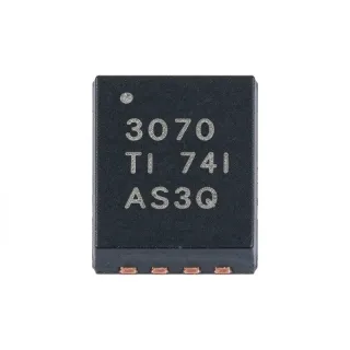
MAX3232IDRE4 - 3V RS-232 Transceiver | Texas Instruments
MPN: MAX3232IDRE4 ✓ ActiveMAX3232IDRE4 Overview
An RS-232 transceiver is an interface IC that converts logic-level TTL or CMOS signals into balanced, bipolar RS-232 line levels and converts received line signals back into logic levels. The MAX3232IDRE4 belongs to the RS-232 interface transceiver hierarchy within integrated circuits and provides the physical-layer conversion required between a digital controller and a serial data port.
The device includes two line drivers and two line receivers, supporting two RS-232 channels in full-duplex operation. Its 3 V to 5.5 V operating range makes it suitable for systems using either 3.3 V or 5 V logic. The 250 kbit/s maximum data rate supports higher-speed point-to-point links, while ±15 kV HBM ESD protection improves robustness when cables connect the board to external equipment.
The MAX3232IDRE4 uses the Maxim RS-232 approach in which on-chip charge pumps generate the positive and negative voltages required by RS-232 transmitters. Four external 0.1 µF capacitors support the charge-pump and transmit functions. This arrangement eliminates the need for a separate negative supply rail while retaining compatibility with established RS-232 interface practice.
Typical uses include industrial serial consoles, point-to-point configuration links, embedded equipment interfaces, and peripheral connectivity. The device can also support full-duplex communication when one driver and one receiver are assigned to each direction. A 16-pin SOIC package supports compact surface-mount PCB construction and automated assembly.
Designers should place the required 0.1 µF capacitors close to their associated pins and observe the polarity and voltage limits given in the manufacturer datasheet. External protection may still be needed for exposed cables or severe electrostatic environments. The maximum cable length and data rate should be selected together because both influence signal integrity and communication reliability.
This product page brings together the principal electrical ratings, package information, drop-in replacement analysis, comparison data, and practical PCB guidance for engineers evaluating the MAX3232IDRE4 in a compact RS-232 interface design.
Drop-in alternatives for MAX3232IDRE4 — same package, pin-to-pin compatible. Different-package parts requiring PCB rework are excluded.
MAX3232EIDRE4
✅ Drop-In📋 Reference alternative (not in catalog)
MAX3232AIDRE4
✅ Drop-In ⚠️ Specs Unverified📋 Reference alternative (not in catalog)
MAX3232CDRE4
✅ Drop-In ⚠️ Specs UnverifiedContact for price
View Datasheet →ST3232CDR
✅ Drop-In📋 Reference alternative (not in catalog)
MAX3232IDRE4 Specifications
| Device Type | RS-232 line driver/receiver transceiver |
| Number of Drivers | 2 |
| Number of Receivers | 2 |
| Supply Voltage Range | 3 V to 5.5 V |
| Maximum Data Rate | 250 kbit/s |
| Duplex Mode | Full duplex |
| ESD Protection | ±15 kV HBM |
| External Charge-Pump Capacitors | 4 × 0.1 µF |
| Technology | CMOS |
| Protocol | RS-232 |
| Operating Temperature | -40 °C to +85 °C |
| Package | 16-pin SOIC, 3.90 mm width |
| Mounting Type | Surface mount |
| Packaging | Tape and reel |
| RoHS Compliance | RoHS3 compliant |
| Transceiver Configuration | 2/2 driver/receiver |
| Manufacturer Recommended Alternate | MAX3232E |
| Pin Count | 16 pins |
MAX3232IDRE4 16-pin soic, 3.90 mm width Pin Configuration Guide
Pin configuration for MAX3232IDRE4 (16-pin soic, 3.90 mm width package). Pin numbering, functions, and connection diagrams are defined in the manufacturer datasheet. Refer to it for the exact footprint and soldering guidelines.

No detailed pinout data available for MAX3232IDRE4.
Refer to the datasheet for full pin configuration.
Typical Applications
MAX3232IDRE4 is suitable for 6 applications: Industrial Serial Console, Point-to-Point Configuration Port, Embedded Peripheral Communication, Instrumentation Data Port, Battery-Powered Field Equipment, RS-232 Test and Service Interface.
Industrial Serial Console
The MAX3232IDRE4 is suitable for an industrial console link because its 3 V to 5.5 V supply range supports embedded 3.3 V and 5 V logic, while its -40 °C to +85 °C rating covers extended industrial environments. Two drivers and two receivers enable a full-duplex channel when each direction uses one transmitter and one receiver. The 250 kbit/s capability supports faster service and configuration links than basic low-speed serial interfaces. Place the four required 0.1 µF capacitors close to their associated pins and maintain a common ground between the equipment and connected peripheral. For cables entering an enclosure, evaluate whether the ±15 kV HBM ESD rating is sufficient or whether additional cable-side protection is required.
Recommended
Point-to-Point Configuration Port
The MAX3232IDRE4 provides a practical interface for a point-to-point configuration link between a controller and an external device. The integrated charge-pump design avoids a separate negative supply rail, while four external 0.1 µF capacitors provide the required support components. A maximum data rate of 250 kbit/s gives design latitude for firmware downloads, diagnostic data, or periodic command traffic. Use one driver for transmit and one receiver for receive to retain full-duplex behavior. Confirm that the attached equipment uses compatible RS-232 signal levels and pin assignment, since connector wiring is not standardized across every RS-232 product. Keep the transceiver-side ground connected to the circuit ground and use the pin-description table in the manufacturer datasheet for every board connection.
Recommended
Embedded Peripheral Communication
The MAX3232IDRE4 fits embedded peripheral communication where a controller needs a robust legacy-style serial interface without a separate negative power rail. Its 3 V minimum supply permits operation from a 3.3 V system, and the 250 kbit/s data rate supports command, status, and bulk-transfer traffic when cable length and signal integrity permit. The 2/2 driver-receiver arrangement can support two RS-232 ports or a full-duplex interface, depending on the board requirements. Because the device is a transceiver rather than a protocol controller, UART settings and application-level framing remain the responsibility of the host processor. Follow the manufacturer datasheet for charge-pump capacitor values, placement, and supply sequencing, and validate the complete cable path during system testing.
Recommended
Instrumentation Data Port
The MAX3232IDRE4 can connect laboratory or industrial instrumentation to a host computer through a full-duplex RS-232 port. Its two transmitters and two receivers provide flexible channel assignment, and the 250 kbit/s maximum rate supports continuous telemetry and command traffic at shorter cable lengths. The 3 V to 5.5 V operating range allows the interface to share a board with modern low-voltage control logic while retaining compatibility with 5 V equipment. The ±15 kV HBM ESD rating improves tolerance to routine connector contact, although bench and industrial environments may require dedicated surge protection. Check grounding and potential ground-loop issues carefully between the host and instrument, and follow the manufacturer datasheet for capacitor placement and line-driver output behavior.
Recommended
Battery-Powered Field Equipment
The 3 V lower supply limit makes the MAX3232IDRE4 applicable to battery-powered field equipment that cannot conveniently generate a negative supply. Integrated charge-pump circuitry develops the bipolar line voltages required by RS-232, while the device can operate across a 3.3 V to 5.5 V system supply range. Two drivers and two receivers allow efficient channel allocation in portable diagnostic or service equipment. The 250 kbit/s rate supports responsive command exchange, although radio-frequency, motor, and display switching circuits should be kept away from the charge-pump and line-driver areas. Use a stable local supply and the four specified 0.1 µF capacitors, and confirm that battery transients remain within the device's permitted supply limits before production release.
Recommended
RS-232 Test and Service Interface
The MAX3232IDRE4 is well suited to service and test interfaces that need bidirectional serial communication between an embedded controller and external equipment. Its full-duplex 2/2 configuration permits simultaneous command transmission and response reception, while the 250 kbit/s rate supports reasonably responsive diagnostic sessions. The 16-pin SOIC package is straightforward to assemble on a compact instrument-control board, and the 3 V to 5.5 V range reduces power-tree complexity. Connect the four required 0.1 µF capacitors according to the manufacturer application circuit and verify the exact numbered pins before layout release. During system validation, test with the intended cable length and peripheral because connector assignments, grounding, and RS-232 electrical limits can otherwise obscure transceiver-level performance.
Recommended
Recommended Products Summary
Engineering reference data for MAX3232IDRE4 — comparison, design guidance, and compliance information.
Selection Guide
Comparison with Alternatives
| Parameter | This Product | MAX3232EIDRE4 | MAX3232AIDRE4 | MAX3232CDRE4 | ST3232CDR |
|---|---|---|---|---|---|
| Brand | Texas Instruments | Texas Instruments | Texas Instruments | Texas Instruments | STMicroelectronics |
| Package | 16-pin SOIC | 16-pin SOIC - same | 16-pin SOIC - same | 16-pin SOIC - same | 16-pin SOIC - same |
| Supply Voltage Range | 3 V to 5.5 V | 3 V to 5.5 V | 3 V to 5.5 V | 3 V to 5.5 V | 3 V operating supply |
Key Differentiators
- Wide low-voltage supply compatibility (vs ST3232CDR)
- Direct manufacturer-supported upgrade path (vs MAX3232EIDRE4)
- Extended industrial temperature coverage (vs MAX3232CDRE4)
Design Notes
Place the four required 0.1 µF charge-pump capacitors close to their corresponding IC pins and follow the exact capacitor network and polarity shown in the manufacturer datasheet. Keep these components away from antenna-sensitive circuits and sensitive analog inputs. Use a short ground return and minimize loop area around the charge-pump network to reduce switching noise and improve conducted-immunity performance.
Assign the RS-232 driver outputs and receiver inputs directly from the numbered pin table before releasing the PCB. Confirm the direction of every logic-side signal and preserve isolation between the two channels. Although the 16-pin SOIC footprint is standardized, lead numbering and exposed-pin arrangements must be checked on every selected ordering code. Do not rely on a family-level drawing when changing to an alternate manufacturer.
Do not treat the ±15 kV HBM rating as a complete cable surge solution. Long or externally exposed RS-232 cables can encounter ESD, lightning-induced transients, and ground-potential differences beyond the board-level rating. Add appropriately coordinated surge protection when required, and ensure the external protection does not distort receiver thresholds or data rates. Validate the completed interface with the intended cable and peripheral.
Select the baud rate and cable length together rather than operating at 250 kbit/s over an unsupported cable run. Although the transceiver supports data rates up to 250 kbit/s, external wiring, connectors, and the attached equipment determine the practical communication distance. Use the manufacturer application guidance for communication-range limits and confirm signal integrity with eye or waveform measurements when the link is long or electrically noisy.
Compliance Information
The product listing identifies the MAX3232IDRE4 as RoHS3 compliant. No separate REACH, halogen-free, or conflict-minerals declaration was established.