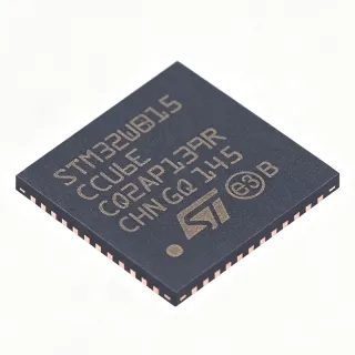
MFRC52201HN1,115 - 13.56MHz RFID Reader IC | NXP | MIFARE
MPN: MFRC52201HN1,115 ✓ Active| Qty | Unit Price | Extended |
|---|---|---|
| 1 | $5.16 | $5.16 |
| 10 | $4.9 | $49.00 |
| 100 | $4.6 | $460.00 |
| 500 | $4.35 | $2,175.00 |
| 1,000 | $4.1 | $4,100.00 |
MFRC52201HN1,115 Overview
An RFID reader IC (also called a contactless reader front-end or NFC initiator IC) is a wireless transceiver integrated circuit that generates a 13.56 MHz carrier, modulates commands onto it, and demodulates responses from passive transponders such as MIFARE cards and NFC tags. It sits within the RF and wireless IC hierarchy, alongside NFC controllers and RFID transceiver chips, forming the analog/digital front end between a host microcontroller and the contactless antenna.
Key features include support for the ISO/IEC 14443 A/MIFARE protocol, three host interfaces (SPI up to 10 Mbit/s, I2C, and serial UART), and an integrated crypto-1 engine for MIFARE Classic authentication. The exposed-pad HVQFN-32 package provides low-inductance ground return for the RF front end and good thermal performance in a compact 5x5 mm-class footprint.
Technically, the MFRC522 integrates the full analog front end: low-dropout voltage regulators for the transmitter supply, a 13.56 MHz oscillator driver for an external crystal, receiver gain stages, and CRC coprocessor. The internal frame handling supports FIFO buffering of 64 bytes, and programmable timers support protocol framing. This reduces host CPU load compared with bit-banged implementations.
Typical applications include 13.56 MHz smart-card readers, point-of-sale terminals, embedded access control, and Arduino/Raspberry Pi hobbyist NFC modules, where the SPI interface and 3.3V supply map directly onto common microcontroller systems.
Design consideration: antenna matching is critical - follow the NXP antenna design guide for L-matching network component values, and note the MFRC52202HN1 (version 2.0) offers improved rough-condition stability and an additional timer prescaler while remaining fully compatible.
This page synthesizes distributor pricing, drop-in family alternatives, and practical design notes not consolidated in the manufacturer datasheet.
Drop-in alternatives for MFRC52201HN1,115 — same package, pin-to-pin compatible. Different-package parts requiring PCB rework are excluded.
Quick Comparison Tool — Select alternative parts for side-by-side comparison:
MFRC52202HN1,115
✅ Drop-In📋 Reference alternative (not in catalog)
MFRC52201HN1,151
✅ Drop-In📋 Reference alternative (not in catalog)
MFRC52201HN1,157
✅ Drop-In📋 Reference alternative (not in catalog)
MFRC52201HN1,115 Specifications
| Function | RFID Reader IC (contactless reader front-end) |
| Frequency | 13.56 MHz |
| Supported Protocol | ISO/IEC 14443 A, MIFARE |
| Host Interfaces | SPI, I2C, UART |
| Supply Voltage | 2.5 V to 3.6 V |
| Operating Supply (typical range) | 2.5 V to 3.3 V |
| Package | 32-pin HVQFN with exposed pad |
| Mounting Type | Surface Mount |
| Packaging | Tape & Reel (T/R) |
| Crypto Engine | Crypto-1 for MIFARE authentication |
| Version | MFRC522 version 1.0 |
| RoHS Status | EU RoHS Compliant |
MFRC52201HN1,115 32-pin hvqfn with exposed pad Pin Configuration Guide
Pin configuration for MFRC52201HN1,115 (32-pin hvqfn with exposed pad package). Pin numbering, functions, and connection diagrams are defined in the manufacturer datasheet. Refer to it for the exact footprint and soldering guidelines.

No detailed pinout data available for MFRC52201HN1,115.
Refer to the datasheet for full pin configuration.
Typical Applications
MFRC52201HN1,115 is suitable for 6 applications: Smart Card / NFC Reader Terminals, Embedded Access Control, Point-of-Sale and Payment Terminals, Arduino / Raspberry Pi Hobbyist and Prototyping, Industrial Identification and Asset Tracking, Battery-Powered Portable and IoT Devices.
Smart Card / NFC Reader Terminals
The MFRC52201HN1,115 is purpose-built for 13.56 MHz smart-card reader terminals: its integrated ISO/IEC 14443 A framing and crypto-1 engine handle MIFARE Classic authentication without host-side encryption overhead. The SPI interface runs at up to 10 Mbit/s-class speeds, so a low-cost MCU can service read transactions within typical terminal timing budgets. Placed directly behind the antenna matching network, the IC's integrated receiver gain stages recover weak tag responses at read ranges of several centimeters with a properly tuned coil. Designs should follow NXP's antenna design guide for L-C matching values.
Recommended
Embedded Access Control
For door access readers and security systems, the MFRC52201HN1,115 reads MIFARE employee cards at 13.56 MHz and delivers card UIDs and sector data over SPI, I2C, or UART to the panel controller. The 2.5V to 3.6V supply allows direct operation from a 3.3V rail shared with the MCU, and low idle current keeps standby power within reader requirements. The crypto-1 engine performs card authentication locally, so secret keys never traverse the interface in plaintext. Select the MFRC52202HN1 v2.0 for improved stability in electrically noisy building environments.
Recommended
Point-of-Sale and Payment Terminals
In POS terminals, the MFRC52201HN1,115 provides the contactless front end for MIFARE-based loyalty cards and closed-loop payment media. Its integrated analog front end - transmitter drivers, VMID reference, and receiver chain - reduces external component count, shrinking the reader module inside compact terminal housings. The UART interface suits payment MCU boards that already use serial links, while CRC coprocessing offloads protocol integrity checks from the host. For EMC-sensitive payment environments, follow NXP's matching network values precisely to keep 13.56 MHz spurious emissions within regulatory limits.
Recommended
Arduino / Raspberry Pi Hobbyist and Prototyping
The MFRC52201HN1,115 is the die inside the ubiquitous RC522 module family, making it the default 13.56 MHz reader for Arduino and Raspberry Pi prototyping. The IC runs natively at 3.3V, matching Raspberry Pi GPIO directly; Arduino 5V boards need level shifting on SCK/MOSI/SS/RST. Open-source MFRC522 libraries expose MIFARE read/write over SPI with a few lines of code, and the IRQ pin enables interrupt-driven polling instead of wasteful continuous scans. SnapEDA provides free symbols, footprints, and 3D models for custom carrier-board designs using the bare HVQFN-32 IC.
Recommended
Industrial Identification and Asset Tracking
In factory asset tracking, the MFRC52201HN1,115 identifies MIFARE-tagged tools, pallets, and work-in-progress at 13.56 MHz, immune to metal-detection interference that affects LF/HF alternatives less predictably. The three host interfaces (SPI, I2C, UART) let the reader integrate with PLC companion modules or existing industrial buses through a bridge MCU. Its 2.5V to 3.6V operation tolerates regulated 3.3V industrial rails with margin. For harsh industrial conditions with vibration and temperature stress, NXP recommends the pin-compatible MFRC52202HN1 v2.0, which explicitly improves rough-condition stability over this v1.0 die.
Recommended
Battery-Powered Portable and IoT Devices
Portable readers, smart locks, and IoT gateways benefit from the MFRC52201HN1,115's 2.5V to 3.6V supply range, which allows direct powering from a single Li-ion cell through a small LDO or even a nearly depleted battery rail. The IC supports power-down modes controllable via the host interface, and the IRQ output wakes the MCU only when a card enters the field, dramatically cutting average current versus continuous polling. The compact HVQFN-32 exposed-pad package fits space-constrained wearable and lock enclosures while its exposed pad provides the low-inductance RF ground the transmitter needs for full read range.
Recommended
Recommended Products Summary
Engineering reference data for MFRC52201HN1,115 — comparison, design guidance, and compliance information.
Selection Guide
Comparison with Alternatives
| Parameter | This Product | MFRC52202HN1,115 | MFRC52201HN1,151 | MFRC52201HN1,157 |
|---|---|---|---|---|
| Package | 32-pin HVQFN EP | 32-pin HVQFN EP - same | 32-pin HVQFN EP - same | 32-pin HVQFN EP - same |
| Brand | NXP Semiconductors | NXP Semiconductors | NXP Semiconductors | NXP Semiconductors |
| Frequency | 13.56 MHz | 13.56 MHz | 13.56 MHz | 13.56 MHz |
| Protocol Support | ISO/IEC 14443 A, MIFARE | ISO/IEC 14443 A, MIFARE | ISO/IEC 14443 A, MIFARE | ISO/IEC 14443 A, MIFARE |
| Host Interfaces | SPI, I2C, UART | SPI, I2C, UART | SPI, I2C, UART | SPI, I2C, UART |
| Supply Voltage | 2.5 V to 3.6 V | 2.5 V to 3.6 V | 2.5 V to 3.6 V | 2.5 V to 3.6 V |
| Die Version | v1.0 | v2.0 (improved stability, extra timer prescaler) | v1.0 | v1.0 |
| PCB Modification Needed | N/A (reference) | None - pin-to-pin compatible | None - identical die | None - identical die |
Key Differentiators
- Triple host interface flexibility (SPI + I2C + UART) (vs ST25R3911B)
- Integrated crypto-1 MIFARE authentication engine (vs PN532)
- Low-voltage operation from 2.5 V (vs MFRC52202HN1,115)
Design Notes
Solder the exposed pad of the HVQFN-32 to a continuous ground plane with multiple thermal vias - it is the primary RF ground return for the transmitter. Place the 13.56 MHz crystal within 5 mm of OSCIN/OSCOUT with short traces, and keep the RX antenna path physically separated from TX traces to prevent transmitter desensitization of the receiver. Decouple TVDD/AVDD pins with 100 nF ceramics placed within 2-3 mm of each pin, plus 4.7-10 uF bulk capacitance near the IC.
The IC is not 5V tolerant - drive SPI/I2C/UART pins only with 3.3V logic; use level shifters when interfacing 5V Arduinos. Never skip the antenna L-C matching network: connecting the coil directly to TX1/TX2 causes detuning, reduced read range, and possible transmitter stress. Note the v1.0 die (this part) has known rough-condition stability limits; if your product sees vibration, ESD events, or wide temperature swings, qualify the pin-compatible MFRC52202HN1 v2.0 early. Verify NXP errata sheets before freezing firmware.
The 13.56 MHz carrier and its harmonics can radiate from poorly matched antenna circuits. Follow NXP's antenna design application note for EMC filter component placement (series inductors and capacitors on TX and RX paths), route the antenna loop on the outer board edge, and keep matching components tight to the IC. If regulatory pre-scan shows 27.12 MHz (2nd harmonic) issues, check for asymmetric antenna drive and confirm both TX pins are driven in the intended differential configuration.
Compliance Information
EU RoHS compliant per Arrow and DigiKey product listings for MFRC52201HN1,115. REACH, halogen-free, and conflict-minerals declarations should be confirmed via NXP official compliance documentation.