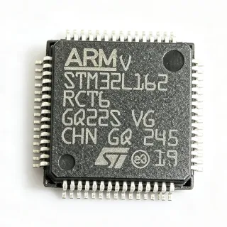
STM32L010RBT6 - Ultra-Low-Power ARM Cortex-M0+ MCU | STMicroelectronics
MPN: STM32L010RBT6 ✓ Active| Qty | Unit Price | Extended |
|---|---|---|
| 1 | $3.5 | $3.50 |
| 10 | $3.15 | $31.50 |
| 100 | $2.8 | $280.00 |
| 500 | $2.45 | $1,225.00 |
| 1,000 | $2.1 | $2,100.00 |
STM32L010RBT6 Overview
What is a microcontroller? A microcontroller (MCU) is a compact integrated circuit designed to govern a specific operation in an embedded system. It contains a processor core, memory (Flash and SRAM), and programmable input/output peripherals on a single chip. Microcontrollers are the brain of countless electronic products, from household appliances to industrial control systems. The STM32L010 series belongs to the STM32L0 family, which is part of the broader STM32 portfolio of 32-bit ARM Cortex-M based MCUs. This family is optimized for ultra-low-power operation, making it ideal for applications where energy efficiency is critical.
Key features of the STM32L010RBT6 include multiple low-power modes (Sleep, Low-power run, Low-power sleep, Stop with RTC, Stop without RTC, Standby with RTC, Standby without RTC), a 12-bit ADC with up to 16 channels, multiple communication interfaces (I2C, SPI, USART), and a variety of timers. The device supports a supply voltage range of 1.8V to 3.6V and operates over a temperature range of -40°C to +85°C. It is RoHS compliant and available in a lead-free package.
From a technical depth perspective, the STM32L010RBT6 leverages the ARM Cortex-M0+ core, which is known for its energy efficiency and small code footprint. The device includes a nested vectored interrupt controller (NVIC), a SysTick timer, and a memory protection unit (MPU) for enhanced reliability. The ultra-low-power design is achieved through advanced power management techniques, including dynamic voltage scaling and multiple low-power modes that allow the MCU to consume as little as 0.29 µA in Standby mode with RTC.
Typical applications include battery-powered sensors, IoT devices, wearable electronics, smart home controllers, and industrial monitoring systems. The STM32L010RBT6 is particularly well-suited for applications that require long battery life, such as wireless sensor nodes and portable medical devices. Its rich set of peripherals and low-power capabilities make it a versatile choice for embedded designers.
When designing with this MCU, it is important to consider the power supply decoupling and the selection of appropriate low-power modes to maximize battery life. The device supports a wide range of clock sources, including an internal RC oscillator and external crystals, allowing designers to optimize for cost and performance. Proper PCB layout, including a solid ground plane and short traces for high-frequency signals, is recommended for reliable operation.
Drop-in alternatives for STM32L010RBT6 — same package, pin-to-pin compatible. Different-package parts requiring PCB rework are excluded.
Quick Comparison Tool — Select alternative parts for side-by-side comparison:
STM32L010R8T6
✅ Drop-In ⚠️ 参数待验证📋 Reference alternative (not in catalog)
STM32L010RCT6
✅ Drop-In ⚠️ 参数待验证📋 Reference alternative (not in catalog)
STM32L010RDT6
✅ Drop-In ⚠️ 参数待验证📋 Reference alternative (not in catalog)
STM32L071RBT6
⚡ Same Package ⚠️ 参数待验证📋 Reference alternative (not in catalog)
STM32L010RBT6 Maximum Ratings & Electrical Characteristics
| Core | ARM Cortex-M0+ |
| Maximum Frequency | 32 MHz |
| Flash Memory | 128 KB |
| SRAM | 20 KB |
| Package | LQFP64 |
| Supply Voltage | 1.8 V to 3.6 V |
| Operating Temperature | -40°C to +85°C |
| ADC Resolution | 12-bit |
| ADC Channels | 16 |
| Communication Interfaces | I2C, SPI, USART |
| Low-Power Modes | Sleep, Low-power run, Low-power sleep, Stop with RTC, Stop without RTC, Standby with RTC, Standby without RTC |
| Standby Current with RTC | 0.29 µA |
| RoHS | Compliant |
| Lead-Free | Yes |
| Mounting Type | Surface Mount |
STM32L010RBT6 Pin Configuration
| Pin 1 | VBAT — Backup battery supply for RTC |
| Pin 2 | PC13 — GPIO / RTC tamper |
| Pin 3 | PC14 — GPIO / OSC32_IN |
| Pin 4 | PC15 — GPIO / OSC32_OUT |
| Pin 5 | PF0 — GPIO / OSC_IN |
| Pin 6 | PF1 — GPIO / OSC_OUT |
| Pin 7 | NRST — Reset (active low) |
| Pin 8 | VDD — Digital power supply |
| Pin 9 | VSS — Ground |
| Pin 10 | PA0 — GPIO / ADC_IN0 |
| Pin 11 | PA1 — GPIO / ADC_IN1 |
| Pin 12 | PA2 — GPIO / USART2_TX |
| Pin 13 | PA3 — GPIO / USART2_RX |
| Pin 14 | PA4 — GPIO / SPI1_NSS |
| Pin 15 | PA5 — GPIO / SPI1_SCK |
| Pin 16 | PA6 — GPIO / SPI1_MISO |
| Pin 17 | PA7 — GPIO / SPI1_MOSI |
| Pin 18 | PB0 — GPIO / ADC_IN8 |
| Pin 19 | PB1 — GPIO / ADC_IN9 |
| Pin 20 | PB2 — GPIO / BOOT1 |
| Pin 21 | PB10 — GPIO / I2C2_SCL |
| Pin 22 | PB11 — GPIO / I2C2_SDA |
| Pin 23 | PB12 — GPIO / SPI2_NSS |
| Pin 24 | PB13 — GPIO / SPI2_SCK |
| Pin 25 | PB14 — GPIO / SPI2_MISO |
| Pin 26 | PB15 — GPIO / SPI2_MOSI |
| Pin 27 | PC6 — GPIO / USART6_TX |
| Pin 28 | PC7 — GPIO / USART6_RX |
| Pin 29 | PC8 — GPIO / USART6_CK |
| Pin 30 | PC9 — GPIO / I2C3_SDA |
| Pin 31 | PA8 — GPIO / MCO |
| Pin 32 | PA9 — GPIO / USART1_TX |
| Pin 33 | PA10 — GPIO / USART1_RX |
| Pin 34 | PA11 — GPIO / USB_DM |
| Pin 35 | PA12 — GPIO / USB_DP |
| Pin 36 | PA13 — GPIO / SWDIO |
| Pin 37 | PA14 — GPIO / SWCLK |
| Pin 38 | PA15 — GPIO / JTDI |
| Pin 39 | PB3 — GPIO / JTDO |
| Pin 40 | PB4 — GPIO / NJTRST |
| Pin 41 | PB5 — GPIO / I2C1_SMBA |
| Pin 42 | PB6 — GPIO / I2C1_SCL |
| Pin 43 | PB7 — GPIO / I2C1_SDA |
| Pin 44 | BOOT0 — Boot mode selection |
| Pin 45 | PB8 — GPIO / I2C1_SCL |
| Pin 46 | PB9 — GPIO / I2C1_SDA |
| Pin 47 | VDD — Digital power supply |
| Pin 48 | VSS — Ground |
| Pin 49 | PC0 — GPIO / ADC_IN10 |
| Pin 50 | PC1 — GPIO / ADC_IN11 |
| Pin 51 | PC2 — GPIO / ADC_IN12 |
| Pin 52 | PC3 — GPIO / ADC_IN13 |
| Pin 53 | PC4 — GPIO / ADC_IN14 |
| Pin 54 | PC5 — GPIO / ADC_IN15 |
| Pin 55 | PD2 — GPIO / USART3_RX |
| Pin 56 | PD3 — GPIO / USART3_TX |
| Pin 57 | PD4 — GPIO / USART3_CK |
| Pin 58 | PD5 — GPIO / USART3_CTS |
| Pin 59 | PD6 — GPIO / USART3_RTS |
| Pin 60 | PD7 — GPIO / USART3_DE |
| Pin 61 | PE0 — GPIO / TIM4_CH1 |
| Pin 62 | PE1 — GPIO / TIM4_CH2 |
| Pin 63 | PE2 — GPIO / TIM4_CH3 |
| Pin 64 | PE3 — GPIO / TIM4_CH4 |
Typical Applications
STM32L010RBT6 is suitable for 6 applications: Battery-Powered Sensors, IoT Devices, Wearable Electronics, Smart Home Controllers, Industrial Monitoring Systems, Portable Medical Devices.
Battery-Powered Sensors
The STM32L010RBT6 is ideal for battery-powered sensors due to its ultra-low-power modes and low standby current of 0.29 µA. It can operate for years on a single coin cell, making it perfect for wireless sensor nodes in IoT applications. The MCU's 12-bit ADC and communication interfaces (I2C, SPI, USART) allow easy integration with various sensors and wireless modules. Designers can leverage the multiple low-power modes to wake the MCU periodically, sample data, and transmit it, maximizing battery life. The wide supply voltage range (1.8V to 3.6V) accommodates battery voltage decay over time, ensuring reliable operation throughout the battery's life.
Recommended
IoT Devices
The STM32L010RBT6 is well-suited for IoT devices that require low power consumption and reliable connectivity. Its ARM Cortex-M0+ core at 32 MHz provides sufficient processing power for IoT protocols like MQTT and CoAP, while the multiple low-power modes enable energy-efficient operation. The MCU supports various communication interfaces (I2C, SPI, USART) to connect to Wi-Fi, Bluetooth, or LoRa modules. The 128 KB Flash memory is ample for IoT firmware, and the 20 KB SRAM supports data buffering. The device's wide operating temperature range (-40°C to +85°C) makes it suitable for outdoor IoT deployments. Designers can use the RTC to schedule wake-ups, reducing average power consumption and extending battery life in remote IoT nodes.
Recommended
Wearable Electronics
The STM32L010RBT6 is an excellent choice for wearable electronics due to its compact LQFP64 package and ultra-low-power operation. The MCU's low-power modes allow it to run on small batteries, such as those used in smartwatches and fitness trackers. The 12-bit ADC can interface with biometric sensors (heart rate, temperature), and the I2C/SPI interfaces connect to displays and other peripherals. The 128 KB Flash memory is sufficient for wearable firmware, and the 20 KB SRAM supports real-time data processing. The device's standby current of 0.29 µA ensures minimal battery drain when the device is idle. Designers can implement efficient power management by using the RTC to wake the MCU periodically for sensor readings, making it ideal for continuous health monitoring.
Recommended
Smart Home Controllers
The STM32L010RBT6 is perfect for smart home controllers, such as thermostats, lighting controls, and security systems. Its low-power consumption allows it to be powered by batteries or energy-harvesting sources, reducing maintenance costs. The MCU's multiple communication interfaces (I2C, SPI, USART) enable seamless integration with various smart home protocols (Zigbee, Z-Wave, Wi-Fi). The 128 KB Flash memory can store complex automation logic, and the 20 KB SRAM supports real-time control. The device's wide supply voltage range (1.8V to 3.6V) is compatible with common power supplies. The RTC feature allows scheduled events, such as turning on lights at sunset, while the low-power modes ensure minimal energy consumption during idle periods.
Recommended
Industrial Monitoring Systems
The STM32L010RBT6 is suitable for industrial monitoring systems that require reliable operation in harsh environments. Its operating temperature range of -40°C to +85°C ensures functionality in extreme conditions. The MCU's 12-bit ADC can interface with industrial sensors (pressure, temperature, vibration), and the USART interface supports Modbus communication for industrial networks. The 128 KB Flash memory is sufficient for monitoring firmware, and the 20 KB SRAM supports data logging. The device's low-power modes are beneficial for remote monitoring stations powered by solar panels or batteries. The wide supply voltage range (1.8V to 3.6V) allows direct connection to industrial power supplies. Designers can use the RTC to timestamp data and schedule periodic transmissions, reducing power consumption and extending system lifespan.
Recommended
Portable Medical Devices
The STM32L010RBT6 is ideal for portable medical devices, such as glucose meters, pulse oximeters, and blood pressure monitors. Its ultra-low-power consumption extends battery life, which is critical for patient convenience and device reliability. The 12-bit ADC provides high-resolution measurements for medical sensors, and the I2C/SPI interfaces connect to displays and memory. The 128 KB Flash memory can store patient data and firmware updates, while the 20 KB SRAM supports real-time processing. The device's standby current of 0.29 µA ensures minimal battery drain when not in use. The wide supply voltage range (1.8V to 3.6V) is compatible with standard medical batteries. Designers can implement safety features using the MCU's built-in peripherals, ensuring accurate and reliable medical monitoring.
Recommended
Recommended Products Summary
Engineering reference data for STM32L010RBT6 — comparison, design guidance, and compliance information.
Selection Guide
Comparison with Alternatives
| Parameter | This Product | STM32L010R8T6 | STM32L010RCT6 | STM32L010RDT6 | STM32L071RBT6 |
|---|---|---|---|---|---|
| Package | LQFP64 | LQFP64 - same | LQFP64 - same | LQFP64 - same | LQFP64 - same |
| Brand | STMicroelectronics | STMicroelectronics | STMicroelectronics | STMicroelectronics | STMicroelectronics |
| Flash Memory | 128 KB | 64 KB | 256 KB | 192 KB | 128 KB |
| SRAM | 20 KB | 8 KB | 20 KB | 20 KB | 20 KB |
| Max Frequency | 32 MHz | 32 MHz | 32 MHz | 32 MHz | 32 MHz |
| ADC Resolution | 12-bit | 12-bit | 12-bit | 12-bit | 12-bit |
| Standby Current with RTC | 0.29 µA | 0.29 µA | 0.29 µA | 0.29 µA | 0.4 µA |
| Pin Compatibility | Reference | Pin-compatible | Pin-compatible | Pin-compatible | Not pin-compatible |
Key Differentiators
- Ultra-low standby current of 0.29 µA with RTC (vs STM32L071RBT6)
- 128 KB Flash memory in a cost-optimized package (vs STM32L010R8T6)
- Pin-compatible with higher-memory variants (vs STM32L010RCT6)
Design Notes
Ensure proper decoupling of the VDD pins with 100nF ceramic capacitors placed as close as possible to each VDD pin. Additionally, use a 4.7µF or larger bulk capacitor near the power input. For battery-powered designs, consider using the low-power modes to reduce average current consumption. The STM32L010RBT6 supports a supply voltage range of 1.8V to 3.6V, so verify that the power supply remains within this range under all load conditions.
Use a solid ground plane and keep high-frequency traces short to minimize EMI. For the crystal oscillator pins (PF0/PF1), place the crystal and load capacitors close to the MCU and ensure a clean ground connection. Follow the layout guidelines in the STM32L0 reference manual (RM0377) for optimal performance. Avoid routing high-speed signals near the oscillator circuit to prevent interference.
When using the RTC, ensure the VBAT pin is connected to a backup battery or a capacitor to maintain timekeeping during main power loss. Also, configure the RTC clock source correctly (LSE or LSI) to avoid unexpected behavior. For programming, use the SWD interface (PA13/PA14) and ensure the BOOT0 pin is set correctly for boot mode. Do not leave unused GPIO pins floating; configure them as outputs or enable pull-ups/pull-downs to reduce leakage current.
Compliance Information
RoHS compliant and lead-free per STMicroelectronics datasheet. AEC-Q100 not applicable for this general-purpose MCU.