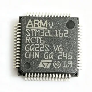
STM8AF5286TCY - 8-bit Automotive MCU, 64KB Flash, LQFP64 | STMicroelectronics
MPN: STM8AF5286TCY ✓ Active| Qty | Unit Price | Extended |
|---|---|---|
| 1 | $6.5 | $6.50 |
| 10 | $5.85 | $58.50 |
| 100 | $5.2 | $520.00 |
| 500 | $4.68 | $2,340.00 |
| 1,000 | $4.16 | $4,160.00 |
STM8AF5286TCY Overview
An 8-bit microcontroller (MCU) is a single-chip computer with an 8-bit central processing unit (CPU), memory, and programmable input/output peripherals. It is a subset of the broader microcontroller family, which includes 16-bit and 32-bit devices. In the system hierarchy, an 8-bit MCU sits below 16-bit and 32-bit MCUs in processing power but offers lower cost, lower power consumption, and simpler architecture, making it ideal for cost-sensitive, high-volume automotive and industrial applications. The STM8A core is an enhanced 8-bit architecture with a three-stage pipeline, delivering up to 20 MIPS at 24 MHz.
Key features include a 24 MHz maximum CPU frequency, 64 KB Flash with read-while-write capability, 6 KB SRAM, and 2 KB true EEPROM with up to 300k write/erase cycles. The device integrates a 10-bit ADC with up to 16 channels, two 16-bit timers, one 8-bit timer, a UART, SPI, and I2C interfaces. It also includes a CAN 2.0B controller, making it suitable for automotive networking. The LQFP64 package provides 52 I/O pins, with 5V-tolerant inputs for direct interfacing with legacy automotive sensors and actuators.
The STM8AF5286TCY is built on ST's proprietary 130nm embedded Flash process, which balances performance, power efficiency, and reliability. The core operates from a 3.3V to 5V supply, with a low-power mode consuming as little as 1 µA in halt mode. The device includes a comprehensive set of safety features, including a window watchdog, clock security system, and a cyclic redundancy check (CRC) unit, supporting ISO 26262 ASIL-B functional safety requirements.
Typical applications include automotive body control modules (BCM), power window and seat control, HVAC control, and motor control for pumps and fans. The CAN interface enables communication with the vehicle's network, while the robust I/O and wide temperature range ensure reliable operation in harsh environments. The device is also used in industrial automation and smart sensors where automotive-grade reliability is required.
When designing with this MCU, ensure proper decoupling of the VDD and VDDA pins with 100nF and 4.7µF capacitors. The NRST pin requires an external pull-up resistor and a capacitor for reliable reset. For CAN communication, a CAN transceiver such as the TJA1051 is required. The device supports in-application programming (IAP) via the UART or CAN, enabling firmware updates in the field.
Drop-in alternatives for STM8AF5286TCY — same package, pin-to-pin compatible. Different-package parts requiring PCB rework are excluded.
Variants in this series
Same-series models that are drop-in compatible with STM8AF5286TCY (same form factor and footprint) — differing in Package, Communication Interfaces, Flash Memory, Timers, ADC Channels.
Quick Comparison Tool — Select alternative parts for side-by-side comparison:
STM8AF5288TCY
✅ Drop-In ⚠️ Specs Unverified✓ In Stock
$1.65 / Unit
View Datasheet →STM8AF5268TCY
✅ Drop-In ⚠️ Specs Unverified✓ In Stock
$3.9 / Unit
View Datasheet →STM8AF5286TCY Maximum Ratings & Electrical Characteristics
| Core | STM8A |
| Bit Size | 8-bit |
| Maximum CPU Frequency | 24 MHz |
| Flash Memory | 64 KB |
| RAM | 6 KB |
| EEPROM | 2 KB |
| Supply Voltage Range | 3 V to 5.5 V |
| Number of I/O Pins | 52 |
| ADC Resolution | 10-bit |
| ADC Channels | 16 |
| Timers | 2x 16-bit, 1x 8-bit |
| Communication Interfaces | UART, SPI, I2C, CAN 2.0B |
| Package | LQFP64 |
| Terminal Form | Gull Wing |
| Number of Terminals | 64 |
| Operating Temperature Range | -40°C to +150°C |
| AEC-Q100 Qualification | Qualified |
| RoHS Status | Compliant |
STM8AF5286TCY Pin Configuration
| Pin 1 | VDD — Power supply |
| Pin 2 | VSS — Ground |
| Pin 3 | NRST — Reset (active low) |
| Pin 4 | PA0 — I/O or ADC input |
| Pin 5 | PA1 — I/O or ADC input |
| Pin 6 | PA2 — I/O or ADC input |
| Pin 7 | PA3 — I/O or ADC input |
| Pin 8 | VSS — Ground |
| Pin 9 | VDD — Power supply |
| Pin 10 | PB0 — I/O or timer input |
| Pin 11 | PB1 — I/O or timer input |
| Pin 12 | PB2 — I/O or timer input |
| Pin 13 | PB3 — I/O or timer input |
| Pin 14 | PB4 — I/O or timer input |
| Pin 15 | PB5 — I/O or timer input |
| Pin 16 | PB6 — I/O or timer input |
| Pin 17 | PB7 — I/O or timer input |
| Pin 18 | VSS — Ground |
| Pin 19 | VDD — Power supply |
| Pin 20 | PC0 — I/O or ADC input |
| Pin 21 | PC1 — I/O or ADC input |
| Pin 22 | PC2 — I/O or ADC input |
| Pin 23 | PC3 — I/O or ADC input |
| Pin 24 | PC4 — I/O or ADC input |
| Pin 25 | PC5 — I/O or ADC input |
| Pin 26 | PC6 — I/O or ADC input |
| Pin 27 | PC7 — I/O or ADC input |
| Pin 28 | VSS — Ground |
| Pin 29 | VDD — Power supply |
| Pin 30 | PD0 — I/O or SPI clock |
| Pin 31 | PD1 — I/O or SPI MOSI |
| Pin 32 | PD2 — I/O or SPI MISO |
| Pin 33 | PD3 — I/O or SPI NSS |
| Pin 34 | PD4 — I/O or UART TX |
| Pin 35 | PD5 — I/O or UART RX |
| Pin 36 | PD6 — I/O or I2C SCL |
| Pin 37 | PD7 — I/O or I2C SDA |
| Pin 38 | VSS — Ground |
| Pin 39 | VDD — Power supply |
| Pin 40 | PE0 — I/O or CAN RX |
| Pin 41 | PE1 — I/O or CAN TX |
| Pin 42 | PE2 — I/O |
| Pin 43 | PE3 — I/O |
| Pin 44 | PE4 — I/O |
| Pin 45 | PE5 — I/O |
| Pin 46 | PE6 — I/O |
| Pin 47 | PE7 — I/O |
| Pin 48 | VSS — Ground |
| Pin 49 | VDD — Power supply |
| Pin 50 | PF0 — I/O or ADC input |
| Pin 51 | PF1 — I/O or ADC input |
| Pin 52 | PF2 — I/O or ADC input |
| Pin 53 | PF3 — I/O or ADC input |
| Pin 54 | PF4 — I/O or ADC input |
| Pin 55 | PF5 — I/O or ADC input |
| Pin 56 | PF6 — I/O or ADC input |
| Pin 57 | PF7 — I/O or ADC input |
| Pin 58 | VSS — Ground |
| Pin 59 | VDD — Power supply |
| Pin 60 | PG0 — I/O |
| Pin 61 | PG1 — I/O |
| Pin 62 | PG2 — I/O |
| Pin 63 | PG3 — I/O |
| Pin 64 | PG4 — I/O |
Typical Applications
STM8AF5286TCY is suitable for 6 applications: Automotive Body Control Module, Motor Control for Pumps and Fans, HVAC Control, Power Window and Seat Control, Industrial Automation, Smart Sensors.
Automotive Body Control Module
The STM8AF5286TCY is ideal for automotive body control modules (BCM) due to its AEC-Q100 qualification, wide temperature range, and CAN 2.0B interface. It manages lighting, wipers, and power windows, with robust I/O for direct sensor and actuator interfacing. The 64 KB Flash provides ample code space for complex control algorithms, while the 10-bit ADC enables analog sensor monitoring. Its low-power modes help reduce quiescent current in standby, critical for battery life. The CAN interface allows seamless integration with the vehicle's network, and the 5V-tolerant I/O simplifies connection to legacy automotive components.
Recommended
Motor Control for Pumps and Fans
The STM8AF5286TCY excels in motor control for pumps and fans, leveraging its 16-bit timers for PWM generation and 10-bit ADC for current sensing. The 24 MHz core provides sufficient processing power for sensorless or sensor-based control algorithms. Its automotive-grade reliability ensures operation in harsh environments, and the CAN interface enables coordination with other vehicle systems. The 64 KB Flash supports complex control loops, while the 2 KB EEPROM stores calibration data. The wide supply voltage range accommodates varying battery conditions, and the low-power modes reduce energy consumption during idle periods.
Recommended
HVAC Control
The STM8AF5286TCY is well-suited for HVAC control in automotive and industrial applications. Its 10-bit ADC reads temperature sensors, while timers generate PWM for fan speed control. The CAN interface allows integration with the vehicle's climate control network. The wide operating temperature range (-40°C to +150°C) ensures reliable operation in extreme conditions. The 64 KB Flash provides ample storage for control algorithms, and the 2 KB EEPROM stores user settings. The 5V-tolerant I/O simplifies interfacing with various sensors and actuators, and the low-power modes help reduce energy consumption when the system is idle.
Recommended
Power Window and Seat Control
The STM8AF5286TCY is perfect for power window and seat control modules. Its robust I/O can directly drive relays or MOSFETs for window motors, while the 10-bit ADC monitors current to detect obstructions. The 16-bit timers generate precise PWM for smooth motor control. The CAN interface enables communication with the central body controller, and the AEC-Q100 qualification ensures reliability in automotive environments. The 64 KB Flash provides ample code space for safety features like anti-pinch detection, and the 2 KB EEPROM stores position calibration data. The wide supply voltage range accommodates battery voltage fluctuations.
Recommended
Industrial Automation
The STM8AF5286TCY is also suitable for industrial automation, where its automotive-grade reliability is an advantage. It can control sensors, actuators, and communication interfaces in factory environments. The 10-bit ADC reads analog sensors, while the UART, SPI, and I2C interfaces connect to various peripherals. The CAN interface enables robust industrial networking. The wide temperature range and 5V-tolerant I/O make it compatible with industrial power supplies and legacy equipment. The 64 KB Flash provides ample storage for control logic, and the low-power modes help reduce energy consumption in always-on systems.
Recommended
Smart Sensors
The STM8AF5286TCY can be used in smart sensors that require local processing and communication. Its 10-bit ADC digitizes sensor signals, while the core processes data and communicates via UART, SPI, I2C, or CAN. The 2 KB EEPROM stores calibration and configuration data. The low-power modes enable battery-powered operation, and the wide supply voltage range accommodates various power sources. The automotive-grade reliability ensures long-term stability in demanding environments. The 64 KB Flash provides ample space for signal processing algorithms, and the 5V-tolerant I/O simplifies interfacing with various sensor types.
Recommended
Recommended Products Summary
Engineering reference data for STM8AF5286TCY — comparison, design guidance, and compliance information.
Selection Guide
Comparison with Alternatives
| Parameter | This Product | STM8AF5288TCY | STM8AF5286UCY | STM8AF5268TCY |
|---|---|---|---|---|
| Package | LQFP64 | LQFP64 | UFQFPN32 | LQFP64 |
| Brand | STMicroelectronics | STMicroelectronics | STMicroelectronics | STMicroelectronics |
| Flash Memory | 64 KB | 128 KB | 64 KB | 32 KB |
| RAM | 6 KB | 6 KB | 6 KB | 6 KB |
| EEPROM | 2 KB | 2 KB | 2 KB | 2 KB |
| Maximum CPU Frequency | 24 MHz | 24 MHz | 24 MHz | 24 MHz |
| Number of I/O Pins | 52 | 52 | 25 | 52 |
| CAN Interface | Yes (2.0B) | Yes (2.0B) | Yes (2.0B) | Yes (2.0B) |
Key Differentiators
- Automotive-grade AEC-Q100 qualification (vs STM8AF5286UCY)
- Larger package with more I/O pins (vs STM8AF5286UCY)
- Balanced memory configuration (vs STM8AF5268TCY)
Design Notes
Decouple the VDD and VDDA pins with 100nF and 4.7µF capacitors placed as close to the pins as possible. Use a low-ESR ceramic capacitor for the 4.7µF to ensure stable operation. The supply voltage range is 3V to 5.5V, so ensure the power supply is within this range under all load conditions.
For the LQFP64 package, ensure proper solder paste stencil design to avoid bridging between pins. Use a 0.5mm pitch footprint with appropriate pad sizes. Provide a ground plane under the MCU to reduce noise and improve thermal performance. Follow ST's layout guidelines for the crystal oscillator and decoupling capacitors.
The NRST pin requires an external pull-up resistor (typically 10kΩ) and a capacitor (100nF) for reliable reset. Do not leave the NRST pin floating. For CAN communication, a transceiver like the TJA1051 is required; ensure proper termination resistors (120Ω) at both ends of the bus. Also, verify that the firmware correctly configures the clock source and PLL for the desired 24 MHz operation.
Compliance Information
AEC-Q100 qualified for automotive applications. RoHS compliant per STMicroelectronics product page.