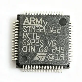
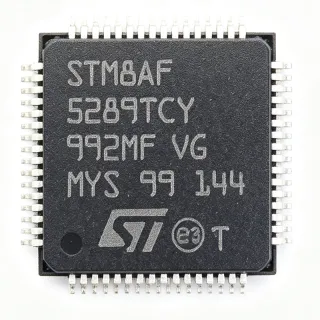
STM32L072RBT6 - Ultra-Low-Power ARM Cortex-M0+ MCU | STMicroelectronics
MPN: STM32L072RBT6 ✓ Active| Qty | Unit Price | Extended |
|---|---|---|
| 1 | $4.5 | $4.50 |
| 10 | $4.05 | $40.50 |
| 100 | $3.6 | $360.00 |
| 500 | $3.24 | $1,620.00 |
| 1,000 | $2.88 | $2,880.00 |
STM32L072RBT6 Overview
An ultra-low-power microcontroller (MCU) is a system-on-chip that combines a processor core, memory, and peripherals while minimizing power consumption to extend battery life. The STM32L0 series is part of the STM32 family, which spans from entry-level Cortex-M0+ to high-performance Cortex-M7 devices. Within the power management hierarchy, these MCUs are designed for applications where energy efficiency is paramount, such as IoT sensors, wearables, and industrial monitoring.
Key features include multiple low-power modes (Sleep, Low-power Run, Low-power Sleep, Stop with RTC, Standby with RTC, and Shutdown), a 12-bit ADC with hardware oversampling, a 12-bit DAC, two comparators, and an ultra-low-power timer. The device also integrates a USB 2.0 full-speed crystal-less interface, an LCD driver supporting up to 8x40 segments, and a true random number generator (TRNG). The operating voltage range is 1.8V to 3.6V, with a typical current consumption of 84 uA/MHz in Run mode and 0.29 uA in Standby mode with RTC.
The STM32L072RBT6 is built on ST's ultra-low-power technology, featuring a flexible clocking scheme with an internal 16 MHz RC oscillator, an external 32.768 kHz crystal for RTC, and a PLL for higher frequencies. The device supports a wide range of communication interfaces including I2C, SPI, USART, and LPUART, enabling seamless connectivity in sensor networks. The integrated LCD driver and USB interface reduce external component count, simplifying board design.
Typical applications include smart meters, medical devices, fitness trackers, wireless sensor nodes, and industrial process control. The ultra-low-power modes allow the MCU to operate for years on a single coin-cell battery, making it a preferred choice for IoT edge devices.
When designing with this MCU, careful attention to the power supply decoupling and the selection of the appropriate low-power mode is essential to achieve the lowest possible energy consumption. The use of the internal RC oscillator can save cost, but for time-critical applications, an external crystal is recommended.
Drop-in alternatives for STM32L072RBT6 — same package, pin-to-pin compatible. Different-package parts requiring PCB rework are excluded.
Variants in this series
Same-series models that are drop-in compatible with STM32L072RBT6 (same form factor and footprint) — differing in ADC, DAC, Package, RTC, Supply Voltage Range.
Quick Comparison Tool — Select alternative parts for side-by-side comparison:
STM32L072RZT6
✅ Drop-In ⚠️ Specs Unverified📋 Reference alternative (not in catalog)
STM32L071RBT6
✅ Drop-In ⚠️ Specs Unverified📋 Reference alternative (not in catalog)
STM32L073RZT6
✅ Drop-In ⚠️ Specs Unverified✓ In Stock
$4.11 / Unit
View Datasheet →STM32L072RBT6TR
✅ Drop-In ⚠️ Specs Unverified📋 Reference alternative (not in catalog)
STM32L072RBT6D
✅ Drop-In ⚠️ Specs Unverified📋 Reference alternative (not in catalog)
STM32L072RBT6 Maximum Ratings & Electrical Characteristics
| Core | ARM Cortex-M0+ |
| Max Clock Speed | 32 MHz |
| Flash Memory | 128 KB |
| SRAM | 20 KB |
| Operating Voltage | 1.8 V to 3.6 V |
| GPIO Pins | 51 |
| ADC Resolution | 12-bit |
| ADC Channels | 16 |
| DAC Resolution | 12-bit |
| DAC Channels | 2 |
| Communication Interfaces | I2C, SPI, USART, LPUART, USB 2.0 |
| Timers | 8 (including low-power timer) |
| Package | LQFP-64 |
| Operating Temperature | -40C to +85C |
| Supply Current (Run mode) | 84 uA/MHz |
| Standby Current (with RTC) | 0.29 uA |
STM32L072RBT6 Pin Configuration
| Pin 1 | VBAT — Battery backup supply for RTC |
| Pin 2 | PC13 — GPIO or TAMPER |
| Pin 3 | PC14 — GPIO or OSC32_IN |
| Pin 4 | PC15 — GPIO or OSC32_OUT |
| Pin 5 | PF0 — GPIO or OSC_IN |
| Pin 6 | PF1 — GPIO or OSC_OUT |
| Pin 7 | NRST — Reset (active low) |
| Pin 8 | VDD — Power supply |
| Pin 9 | VSS — Ground |
| Pin 10 | VDDA — Analog power supply |
| Pin 11 | PA0 — GPIO/ADC_IN0 |
| Pin 12 | PA1 — GPIO/ADC_IN1 |
| Pin 13 | PA2 — GPIO/USART2_TX |
| Pin 14 | PA3 — GPIO/USART2_RX |
| Pin 15 | PA4 — GPIO/SPI1_NSS |
| Pin 16 | PA5 — GPIO/SPI1_SCK |
| Pin 17 | PA6 — GPIO/SPI1_MISO |
| Pin 18 | PA7 — GPIO/SPI1_MOSI |
| Pin 19 | PB0 — GPIO/ADC_IN8 |
| Pin 20 | PB1 — GPIO/ADC_IN9 |
| Pin 21 | PB2 — GPIO/BOOT1 |
| Pin 22 | PB10 — GPIO/I2C2_SCL |
| Pin 23 | PB11 — GPIO/I2C2_SDA |
| Pin 24 | PB12 — GPIO/SPI2_NSS |
| Pin 25 | PB13 — GPIO/SPI2_SCK |
| Pin 26 | PB14 — GPIO/SPI2_MISO |
| Pin 27 | PB15 — GPIO/SPI2_MOSI |
| Pin 28 | PC6 — GPIO/USART6_TX |
| Pin 29 | PC7 — GPIO/USART6_RX |
| Pin 30 | PC8 — GPIO |
| Pin 31 | PC9 — GPIO |
| Pin 32 | PD2 — GPIO |
| Pin 33 | PH0 — GPIO/OSC_IN |
| Pin 34 | PH1 — GPIO/OSC_OUT |
| Pin 35 | PB3 — GPIO/SPI1_SCK |
| Pin 36 | PB4 — GPIO/SPI1_MISO |
| Pin 37 | PB5 — GPIO/I2C1_SMBA |
| Pin 38 | PB6 — GPIO/I2C1_SCL |
| Pin 39 | PB7 — GPIO/I2C1_SDA |
| Pin 40 | BOOT0 — Boot mode selection |
| Pin 41 | PB8 — GPIO/I2C1_SCL |
| Pin 42 | PB9 — GPIO/I2C1_SDA |
| Pin 43 | PA8 — GPIO/USART1_CK |
| Pin 44 | PA9 — GPIO/USART1_TX |
| Pin 45 | PA10 — GPIO/USART1_RX |
| Pin 46 | PA11 — GPIO/USB_DM |
| Pin 47 | PA12 — GPIO/USB_DP |
| Pin 48 | PA13 — GPIO/SWDIO |
| Pin 49 | PA14 — GPIO/SWCLK |
| Pin 50 | PA15 — GPIO/SPI1_NSS |
| Pin 51 | PC10 — GPIO/USART4_TX |
| Pin 52 | PC11 — GPIO/USART4_RX |
| Pin 53 | PC12 — GPIO/USART5_TX |
| Pin 54 | PD0 — GPIO/OSC_IN |
| Pin 55 | PD1 — GPIO/OSC_OUT |
| Pin 56 | PD3 — GPIO |
| Pin 57 | PD4 — GPIO |
| Pin 58 | PD5 — GPIO |
| Pin 59 | PD6 — GPIO |
| Pin 60 | PD7 — GPIO |
| Pin 61 | PE0 — GPIO |
| Pin 62 | PE1 — GPIO |
| Pin 63 | VDD — Power supply |
| Pin 64 | VSS — Ground |
Typical Applications
STM32L072RBT6 is suitable for 6 applications: IoT Sensor Nodes, Smart Meters, Wearable Fitness Trackers, Medical Devices, Industrial Process Control, Smart Home Devices.
IoT Sensor Nodes
The STM32L072RBT6 is ideal for IoT sensor nodes due to its ultra-low-power consumption and multiple communication interfaces. In a typical application, the MCU wakes up periodically from Stop mode to read sensors via I2C or SPI, process data, and transmit via LPUART or a sub-GHz radio. The 0.29 uA standby current with RTC ensures long battery life, while the 12-bit ADC with hardware oversampling provides accurate sensor readings. The integrated USB interface allows for easy firmware updates and data logging. Compared to higher-power MCUs, the STM32L072RBT6 extends battery life by up to 10x in duty-cycled applications.
Recommended
Smart Meters
Smart meters require reliable, low-power operation over many years. The STM32L072RBT6's ultra-low-power modes and integrated LCD driver make it suitable for displaying consumption data. The 12-bit ADC can measure voltage and current with high accuracy, while the multiple timers enable precise pulse counting. The device's wide operating voltage range (1.8V-3.6V) accommodates battery or energy-harvesting power sources. The standby current of 0.29 uA ensures minimal power draw during idle periods, extending battery life to 10+ years in typical metering applications.
Recommended
Wearable Fitness Trackers
Wearable devices demand ultra-low power and small form factor. The STM32L072RBT6's 32 MHz Cortex-M0+ core provides sufficient processing for sensor fusion algorithms, while its low-power modes allow the device to run for weeks on a small battery. The integrated DAC can drive haptic actuators, and the USB interface enables charging and data transfer. The device's 1.8V operation is compatible with single-cell batteries, and the 20 KB SRAM is adequate for buffering sensor data. The low-power timer can wake the MCU periodically to sample accelerometer data, minimizing power consumption.
Recommended
Medical Devices
In medical devices such as glucose monitors and pulse oximeters, the STM32L072RBT6 provides reliable, low-power operation. The 12-bit ADC with oversampling ensures accurate sensor readings, while the multiple communication interfaces allow data transfer to a host system. The device's low-power modes are critical for battery-operated devices that must last for months. The integrated TRNG can be used for security protocols, and the wide operating temperature range (-40C to +85C) ensures operation in various environments. The 128 KB Flash is sufficient for complex algorithms and data logging.
Recommended
Industrial Process Control
The STM32L072RBT6 is suitable for industrial process control due to its robust communication interfaces and low-power operation. It can interface with sensors and actuators via UART, SPI, or I2C, and its multiple timers can generate PWM signals for motor control. The device's wide operating voltage range and temperature range make it suitable for harsh industrial environments. The low-power modes allow the system to conserve energy during idle periods, reducing overall power consumption. The integrated DAC can be used for analog output, and the ADC for monitoring process variables.
Recommended
Smart Home Devices
Smart home devices such as thermostats and smart locks benefit from the STM32L072RBT6's low power and connectivity. The device can communicate via Zigbee, Z-Wave, or Bluetooth through external modules, while its low-power modes ensure long battery life. The integrated LCD driver can display status information, and the USB interface allows for easy configuration. The 12-bit ADC can monitor battery voltage, and the multiple timers can handle debouncing and timeouts. The device's small footprint and low cost make it ideal for mass-produced smart home products.
Recommended
Recommended Products Summary
Engineering reference data for STM32L072RBT6 — comparison, design guidance, and compliance information.
Selection Guide
Comparison with Alternatives
| Parameter | This Product | STM32L072RZT6 | STM32L071RBT6 | STM32L073RZT6 |
|---|---|---|---|---|
| Package | LQFP-64 | LQFP-64 | LQFP-64 | LQFP-64 |
| Brand | STMicroelectronics | STMicroelectronics | STMicroelectronics | STMicroelectronics |
| Flash Memory | 128 KB | 192 KB | 128 KB | 192 KB |
| SRAM | 20 KB | 20 KB | 20 KB | 20 KB |
| USB Interface | Yes | Yes | No | Yes |
| DAC | Yes (2 channels) | Yes (2 channels) | No | Yes (2 channels) |
| LCD Driver | Yes (8x40) | Yes (8x40) | No | Yes (8x40) |
| Standby Current (with RTC) | 0.29 uA | 0.29 uA | 0.29 uA | 0.29 uA |
Key Differentiators
- Integrated USB without external crystal (vs STM32L071RBT6)
- Integrated LCD driver (vs STM32L071RBT6)
- Higher Flash option available (vs STM32L072RZT6)
Design Notes
For ultra-low-power operation, use the appropriate low-power mode. In Standby mode with RTC, the current is 0.29 uA. Ensure that all unused GPIOs are configured as analog inputs or outputs to avoid floating inputs that increase leakage. Use the internal RC oscillator for cost savings, but for time-critical applications, use an external 32.768 kHz crystal for the RTC.
Place decoupling capacitors (100 nF) close to each VDD pin and a 4.7 uF capacitor on VDDA. For the USB interface, route the D+ and D- lines as a differential pair with controlled impedance (90 ohms). Keep the crystal oscillator traces short and away from high-speed digital signals to minimize noise.
Do not exceed the absolute maximum ratings, especially on the VBAT pin. When using the internal LCD driver, ensure the LCD voltage is within the specified range. For firmware, enable the brown-out reset (BOR) to prevent erratic behavior during power supply dips. Also, configure the GPIOs correctly to avoid excessive current draw.
Compliance Information
STMicroelectronics products are RoHS compliant and lead-free. AEC-Q100 qualification is not applicable for this standard-grade MCU.