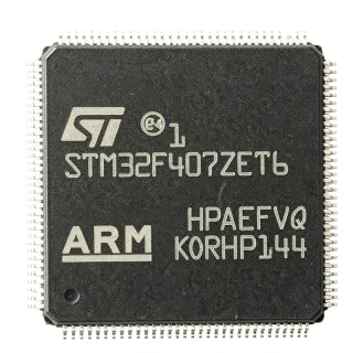
STM32F437ZIT6 - 2MB Flash, 180MHz ARM Cortex-M4 MCU | STMicroelectronics
N.º da peça: STM32F437ZIT6 ✓ Ativo| Qtd. | Preço unitário | Total |
|---|---|---|
| 1 | $12.5 | $12,50 |
| 10 | $11.2 | $112,00 |
| 100 | $9.8 | $980,00 |
| 500 | $8.9 | $4.450,00 |
| 1.000 | $8.1 | $8.100,00 |
STM32F437ZIT6 Visão geral
What is an ARM Cortex-M4 microcontroller? It is a 32-bit processor core designed for embedded systems, offering a balance of performance, power efficiency, and rich peripheral integration. The Cortex-M4 includes a floating-point unit (FPU) and DSP instructions, enabling efficient handling of mathematical and signal-processing tasks. In the system hierarchy, a microcontroller (MCU) integrates a processor core, memory, and programmable peripherals on a single chip, serving as the 'brain' of embedded systems. The STM32F4 series sits within the broader STM32 family, which spans from low-power Cortex-M0 to high-performance Cortex-M7 devices, and is widely used in industrial, consumer, and automotive applications.
Key features of the STM32F437ZIT6 include a 180 MHz CPU with 225 DMIPS/1.25 DMIPS/MHz, a Chrom-ART Accelerator for 2D graphics, a TFT-LCD controller, a camera interface, and a true random number generator. It also integrates multiple communication interfaces: 4 USARTs, 2 UARTs, 6 SPIs, 3 I2Cs, 2 CANs, 1 SDIO, 1 USB 2.0 OTG FS/HS, and 1 Ethernet MAC. The device supports up to 168 MHz for the ADC, with three 12-bit ADCs, two DACs, and multiple timers including advanced-control timers for motor control.
Technically, the STM32F437ZIT6 is built on a 90 nm process technology, offering a good balance of speed and power consumption. It operates from 1.8V to 3.6V supply, with a wide temperature range of -40°C to +85°C (T suffix). The device includes a power-on reset, brown-out reset, and a programmable voltage detector, ensuring reliable operation. The memory architecture supports external memory interfaces via FSMC (Flexible Static Memory Controller) for SRAM, PSRAM, NOR, and NAND Flash, expanding storage beyond the internal 2 MB.
Typical applications include industrial control systems, motor drives, medical devices, consumer electronics, and IoT gateways. The combination of high CPU performance, rich connectivity, and graphics capabilities makes it ideal for human-machine interfaces (HMIs), PLCs, and advanced robotics. For example, in an industrial HMI, the TFT-LCD controller and Chrom-ART accelerator enable smooth graphical rendering, while the Ethernet MAC and CAN interfaces facilitate industrial networking.
When designing with this device, ensure adequate decoupling on all power pins and a proper ground plane. The 144-pin LQFP package requires careful PCB layout for thermal management and signal integrity, especially for high-speed interfaces like Ethernet and USB. Use the internal voltage regulator for core logic, and consider external memory if the application requires more than 2 MB of code or 256 KB of data.
Alternativas drop-in para STM32F437ZIT6 — mesmo encapsulamento, compatível pino a pino. Peças de encapsulamento diferente que exigem retrabalho na PCB são excluídas.
Variantes desta série
Modelos da mesma série compatíveis como drop-in com STM32F437ZIT6 (mesmo formato e footprint) — diferindo em Core, Timers, ADC, Package, Communication Interfaces.
Ferramenta de comparação rápida — selecione peças alternativas para comparação lado a lado:
STM32F429ZIT6
✅ Drop-In ⚠️ Especificações não verificadas✓ Em estoque
$11.4 / unidade
Ver ficha técnica →STM32F439ZIT6
✅ Drop-In ⚠️ Especificações não verificadas📋 Alternativa de referência (fora do catálogo)
STM32F407ZIT6
✅ Drop-In ⚠️ Especificações não verificadas📋 Alternativa de referência (fora do catálogo)
STM32F437ZIT7
✅ Drop-In ⚠️ Especificações não verificadas📋 Alternativa de referência (fora do catálogo)
STM32F437ZIT6TR
✅ Drop-In ⚠️ Especificações não verificadas📋 Alternativa de referência (fora do catálogo)
STM32F437ZIT6 Classificações máximas e características elétricas
| Core | ARM Cortex-M4 with FPU |
| Max Clock Speed | 180 MHz |
| Flash Memory | 2 MB |
| SRAM | 256 KB |
| Tensão de alimentação | 1.8V to 3.6V |
| Temperatura de operação | -40°C to +85°C |
| Encapsulamento | LQFP144 (20x20 mm) |
| GPIO Pins | 114 |
| ADC | 3x 12-bit, up to 24 channels |
| DAC | 2x 12-bit |
| Timers | 12x 16-bit, 2x 32-bit |
| Communication Interfaces | 4x USART, 2x UART, 6x SPI, 3x I2C, 2x CAN, 1x SDIO, 1x USB OTG FS/HS, 1x Ethernet MAC |
| DMA | 16-stream DMA controller |
| Graphics | TFT-LCD controller, Chrom-ART Accelerator |
| RoHS | Compliant |
Configuração de pinos do STM32F437ZIT6
| Pino 1 | PE2 — GPIO / FSMC_A23 |
| Pino 2 | PE3 — GPIO / FSMC_A19 |
| Pino 3 | PE4 — GPIO / FSMC_A20 |
| Pino 4 | PE5 — GPIO / FSMC_A21 |
| Pino 5 | PE6 — GPIO / FSMC_A22 |
| Pino 6 | VBAT — Battery backup supply |
| Pino 7 | PC13 — GPIO / RTC_TAMP1 |
| Pino 8 | PC14 — GPIO / OSC32_IN |
| Pino 9 | PC15 — GPIO / OSC32_OUT |
| Pino 10 | PF0 — GPIO / FSMC_A0 |
| Pino 11 | PF1 — GPIO / FSMC_A1 |
| Pino 12 | PF2 — GPIO / FSMC_A2 |
| Pino 13 | PF3 — GPIO / FSMC_A3 |
| Pino 14 | PF4 — GPIO / FSMC_A4 |
| Pino 15 | PF5 — GPIO / FSMC_A5 |
| Pino 16 | VSS — Ground |
| Pino 17 | VDD — Power supply |
| Pino 18 | PF6 — GPIO / FSMC_NWAIT |
| Pino 19 | PF7 — GPIO / FSMC_NE1 |
| Pino 20 | PF8 — GPIO / FSMC_NCE2 |
| Pino 21 | PF9 — GPIO / FSMC_NCE3 |
| Pino 22 | PF10 — GPIO / FSMC_NE4 |
| Pino 23 | PH0 — GPIO / OSC_IN |
| Pino 24 | PH1 — GPIO / OSC_OUT |
| Pino 25 | PH2 — GPIO / FSMC_SDCKE0 |
| Pino 26 | PH3 — GPIO / FSMC_SDNE0 |
| Pino 27 | PH4 — GPIO / FSMC_SDNE1 |
| Pino 28 | PH5 — GPIO / FSMC_SDNWE |
| Pino 29 | PH6 — GPIO / FSMC_SDNE2 |
| Pino 30 | PH7 — GPIO / FSMC_SDCKE1 |
| Pino 31 | PH8 — GPIO / FSMC_D16 |
| Pino 32 | PH9 — GPIO / FSMC_D17 |
| Pino 33 | PH10 — GPIO / FSMC_D18 |
| Pino 34 | PH11 — GPIO / FSMC_D19 |
| Pino 35 | PH12 — GPIO / FSMC_D20 |
| Pino 36 | PH13 — GPIO / FSMC_D21 |
| Pino 37 | PH14 — GPIO / FSMC_D22 |
| Pino 38 | PH15 — GPIO / FSMC_D23 |
| Pino 39 | VSS — Ground |
| Pino 40 | VDD — Power supply |
| Pino 41 | PI0 — GPIO / FSMC_D24 |
| Pino 42 | PI1 — GPIO / FSMC_D25 |
| Pino 43 | PI2 — GPIO / FSMC_D26 |
| Pino 44 | PI3 — GPIO / FSMC_D27 |
| Pino 45 | PI4 — GPIO / FSMC_D28 |
| Pino 46 | PI5 — GPIO / FSMC_D29 |
| Pino 47 | PI6 — GPIO / FSMC_D30 |
| Pino 48 | PI7 — GPIO / FSMC_D31 |
| Pino 49 | PD0 — GPIO / FSMC_D2 |
| Pino 50 | PD1 — GPIO / FSMC_D3 |
| Pino 51 | PD2 — GPIO / FSMC_D4 |
| Pino 52 | PD3 — GPIO / FSMC_D5 |
| Pino 53 | PD4 — GPIO / FSMC_D6 |
| Pino 54 | PD5 — GPIO / FSMC_D7 |
| Pino 55 | PD6 — GPIO / FSMC_D8 |
| Pino 56 | PD7 — GPIO / FSMC_D9 |
| Pino 57 | PD8 — GPIO / FSMC_D10 |
| Pino 58 | PD9 — GPIO / FSMC_D11 |
| Pino 59 | PD10 — GPIO / FSMC_D12 |
| Pino 60 | PD11 — GPIO / FSMC_D13 |
| Pino 61 | PD12 — GPIO / FSMC_D14 |
| Pino 62 | PD13 — GPIO / FSMC_D15 |
| Pino 63 | PD14 — GPIO / FSMC_D0 |
| Pino 64 | PD15 — GPIO / FSMC_D1 |
| Pino 65 | VSS — Ground |
| Pino 66 | VDD — Power supply |
| Pino 67 | PC0 — GPIO / ADC123_IN10 |
| Pino 68 | PC1 — GPIO / ADC123_IN11 |
| Pino 69 | PC2 — GPIO / ADC123_IN12 |
| Pino 70 | PC3 — GPIO / ADC123_IN13 |
| Pino 71 | PC4 — GPIO / ADC12_IN14 |
| Pino 72 | PC5 — GPIO / ADC12_IN15 |
| Pino 73 | PB2 — GPIO / BOOT1 |
| Pino 74 | PE7 — GPIO / FSMC_D4 |
| Pino 75 | PE8 — GPIO / FSMC_D5 |
| Pino 76 | PE9 — GPIO / FSMC_D6 |
| Pino 77 | PE10 — GPIO / FSMC_D7 |
| Pino 78 | PE11 — GPIO / FSMC_D8 |
| Pino 79 | PE12 — GPIO / FSMC_D9 |
| Pino 80 | PE13 — GPIO / FSMC_D10 |
| Pino 81 | PE14 — GPIO / FSMC_D11 |
| Pino 82 | PE15 — GPIO / FSMC_D12 |
| Pino 83 | PB10 — GPIO / I2C2_SCL / USART3_TX |
| Pino 84 | PB11 — GPIO / I2C2_SDA / USART3_RX |
| Pino 85 | VSS — Ground |
| Pino 86 | VDD — Power supply |
| Pino 87 | PB12 — GPIO / SPI2_NSS / I2C2_SMBA |
| Pino 88 | PB13 — GPIO / SPI2_SCK / I2C2_SCL |
| Pino 89 | PB14 — GPIO / SPI2_MISO / I2C2_SDA |
| Pino 90 | PB15 — GPIO / SPI2_MOSI |
| Pino 91 | PD8 — GPIO / USART3_TX / FSMC_D13 |
| Pino 92 | PD9 — GPIO / USART3_RX / FSMC_D14 |
| Pino 93 | PD10 — GPIO / USART3_CK / FSMC_D15 |
| Pino 94 | PD11 — GPIO / USART3_CTS / FSMC_D16 |
| Pino 95 | PD12 — GPIO / USART3_RTS / FSMC_D17 |
| Pino 96 | PD13 — GPIO / USART3_DE / FSMC_D18 |
| Pino 97 | PD14 — GPIO / USART3_DE / FSMC_D19 |
| Pino 98 | PD15 — GPIO / USART3_DE / FSMC_D20 |
| Pino 99 | PC6 — GPIO / I2S2_MCK / USART6_TX |
| Pino 100 | PC7 — GPIO / I2S2_MCK / USART6_RX |
| Pino 101 | PC8 — GPIO / I2S2_SCK / USART6_CK |
| Pino 102 | PC9 — GPIO / I2S2_WS / USART6_CTS |
| Pino 103 | PA0 — GPIO / ADC123_IN0 / WKUP |
| Pino 104 | PA1 — GPIO / ADC123_IN1 |
| Pino 105 | PA2 — GPIO / ADC123_IN2 / USART2_TX |
| Pino 106 | PA3 — GPIO / ADC123_IN3 / USART2_RX |
| Pino 107 | VSS — Ground |
| Pino 108 | VDD — Power supply |
| Pino 109 | PA4 — GPIO / ADC12_IN4 / DAC_OUT1 |
| Pino 110 | PA5 — GPIO / ADC12_IN5 / DAC_OUT2 |
| Pino 111 | PA6 — GPIO / ADC12_IN6 / SPI1_MISO |
| Pino 112 | PA7 — GPIO / ADC12_IN7 / SPI1_MOSI |
| Pino 113 | PC4 — GPIO / ADC12_IN14 |
| Pino 114 | PC5 — GPIO / ADC12_IN15 |
| Pino 115 | PB0 — GPIO / ADC12_IN8 |
| Pino 116 | PB1 — GPIO / ADC12_IN9 |
| Pino 117 | PB2 — GPIO / BOOT1 |
| Pino 118 | PE7 — GPIO / FSMC_D4 |
| Pino 119 | PE8 — GPIO / FSMC_D5 |
| Pino 120 | PE9 — GPIO / FSMC_D6 |
| Pino 121 | PE10 — GPIO / FSMC_D7 |
| Pino 122 | PE11 — GPIO / FSMC_D8 |
| Pino 123 | PE12 — GPIO / FSMC_D9 |
| Pino 124 | PE13 — GPIO / FSMC_D10 |
| Pino 125 | PE14 — GPIO / FSMC_D11 |
| Pino 126 | PE15 — GPIO / FSMC_D12 |
| Pino 127 | PB10 — GPIO / I2C2_SCL / USART3_TX |
| Pino 128 | PB11 — GPIO / I2C2_SDA / USART3_RX |
| Pino 129 | VSS — Ground |
| Pino 130 | VDD — Power supply |
| Pino 131 | PB12 — GPIO / SPI2_NSS / I2C2_SMBA |
| Pino 132 | PB13 — GPIO / SPI2_SCK / I2C2_SCL |
| Pino 133 | PB14 — GPIO / SPI2_MISO / I2C2_SDA |
| Pino 134 | PB15 — GPIO / SPI2_MOSI |
| Pino 135 | PD8 — GPIO / USART3_TX / FSMC_D13 |
| Pino 136 | PD9 — GPIO / USART3_RX / FSMC_D14 |
| Pino 137 | PD10 — GPIO / USART3_CK / FSMC_D15 |
| Pino 138 | PD11 — GPIO / USART3_CTS / FSMC_D16 |
| Pino 139 | PD12 — GPIO / USART3_RTS / FSMC_D17 |
| Pino 140 | PD13 — GPIO / USART3_DE / FSMC_D18 |
| Pino 141 | PD14 — GPIO / USART3_DE / FSMC_D19 |
| Pino 142 | PD15 — GPIO / USART3_DE / FSMC_D20 |
| Pino 143 | PC6 — GPIO / I2S2_MCK / USART6_TX |
| Pino 144 | PC7 — GPIO / I2S2_MCK / USART6_RX |
Aplicações típicas
STM32F437ZIT6 é adequado para 6 aplicaçãos: Industrial Control Systems, Human-Machine Interface (HMI), IoT Gateway, Medical Devices, Consumer Electronics, Test and Measurement.
Industrial Control Systems
The STM32F437ZIT6 is ideal for industrial control systems such as PLCs, motor drives, and robotics. Its 180 MHz Cortex-M4 core with FPU handles complex control algorithms like FOC and PID loops in real time. The advanced-control timers generate precise PWM signals with dead-time insertion for motor control. The device's multiple communication interfaces (CAN, Ethernet, UART, SPI) enable seamless integration into industrial networks. The wide operating temperature range (-40°C to +85°C) ensures reliability in harsh environments. The 2 MB Flash allows storing large firmware and data logs, while the 256 KB SRAM supports real-time data processing. The FSMC interface can connect to external memory for expanded storage. The TFT-LCD controller and Chrom-ART accelerator enable graphical HMIs for operator interfaces. The device's robust design, including brown-out reset and watchdog timers, ensures fail-safe operation in critical applications. Overall, the STM32F437ZIT6 provides the performance, connectivity, and reliability required for modern industrial automation.
Recomendado
Human-Machine Interface (HMI)
The STM32F437ZIT6 excels in HMI applications due to its integrated TFT-LCD controller and Chrom-ART Accelerator. The TFT-LCD controller supports up to XGA resolution, enabling vibrant graphical displays. The Chrom-ART Accelerator offloads 2D graphics operations from the CPU, ensuring smooth animations and fast screen updates. The 2 MB Flash provides ample storage for graphical assets and fonts. The device's high-speed interfaces (USB, Ethernet, UART) allow connectivity to external systems for data exchange. The 114 GPIO pins support touchscreens, buttons, and LEDs. The FPU accelerates mathematical operations for graphics transformations. The device's low power consumption and wide supply voltage range make it suitable for portable HMIs. In a typical HMI, the STM32F437ZIT6 drives a TFT-LCD panel via the parallel interface, reads touch input via SPI or I2C, and communicates with a host system via Ethernet or USB. The Chrom-ART Accelerator handles image rendering, freeing the CPU for application logic. The result is a responsive, feature-rich user interface with minimal CPU load.
Recomendado
IoT Gateway
The STM32F437ZIT6 is a powerful choice for IoT gateways, combining high performance with rich connectivity. The integrated Ethernet MAC enables wired network access, while USB OTG supports cellular modems or Wi-Fi modules. The device's multiple UARTs, SPIs, and I2Cs allow connection to various sensors and actuators. The 2 MB Flash and 256 KB SRAM provide ample resources for protocol stacks (e.g., MQTT, CoAP) and data buffering. The crypto/hash processor (on F439 variant) enhances security for encrypted communications. The device's low power modes (Sleep, Stop, Standby) help optimize energy consumption in battery-powered gateways. The TFT-LCD controller can drive a local display for status monitoring. In a typical IoT gateway, the STM32F437ZIT6 collects data from sensors via UART/SPI, processes it locally, and transmits it to the cloud via Ethernet or Wi-Fi. The device's high clock speed ensures real-time data processing, while the DMA controller offloads data transfers, reducing CPU load. The result is a reliable, secure, and efficient gateway for smart home, industrial, and agricultural applications.
Recomendado
Medical Devices
The STM32F437ZIT6 is well-suited for medical devices such as patient monitors, infusion pumps, and diagnostic equipment. Its high-performance core and FPU enable complex signal processing for ECG, EEG, and imaging. The multiple ADCs (up to 24 channels) allow simultaneous sampling of multiple physiological signals. The device's low power consumption and wide supply voltage range support battery-operated portable devices. The TFT-LCD controller can drive high-resolution displays for waveforms and patient data. The communication interfaces (USB, UART, CAN) enable data transfer to hospital networks or PCs. The device's reliability features, including watchdog timers and brown-out reset, ensure safe operation in critical medical applications. The 2 MB Flash allows storing patient data and firmware updates. In a typical patient monitor, the STM32F437ZIT6 acquires ECG signals via ADCs, processes them using DSP instructions, and displays the waveform on an LCD. The device's real-time capabilities ensure accurate monitoring, while the Ethernet interface allows remote monitoring by healthcare professionals.
Recomendado
Consumer Electronics
The STM32F437ZIT6 is used in high-end consumer electronics such as smart home hubs, audio systems, and wearable devices. Its powerful core and graphics capabilities enable rich user interfaces and multimedia processing. The TFT-LCD controller and Chrom-ART Accelerator support smooth animations and video playback. The device's audio interfaces (I2S, SAI) allow high-quality audio processing. The USB OTG supports connectivity to smartphones and PCs. The device's low power modes extend battery life in portable devices. The 2 MB Flash provides ample storage for firmware and media assets. In a smart home hub, the STM32F437ZIT6 manages multiple wireless protocols (Zigbee, Z-Wave) via external modules, controls smart devices, and provides a touchscreen interface. The device's high performance ensures responsive control, while the Ethernet interface enables internet connectivity. The result is a versatile, feature-rich consumer product.
Recomendado
Test and Measurement
The STM32F437ZIT6 is ideal for test and measurement equipment such as oscilloscopes, data loggers, and signal generators. Its high-speed ADCs (up to 2.4 MSPS) enable accurate signal acquisition. The DMA controller allows continuous data streaming without CPU intervention. The device's multiple timers generate precise timing signals for triggering and synchronization. The TFT-LCD controller displays waveforms and measurement results. The USB and Ethernet interfaces enable remote control and data transfer. The 2 MB Flash stores firmware and calibration data. In a portable oscilloscope, the STM32F437ZIT6 samples analog signals via ADCs, processes them using DSP instructions, and displays the waveform on an LCD. The device's high clock speed ensures real-time processing, while the FPU accelerates mathematical operations for measurements. The result is a compact, cost-effective test instrument.
Recomendado
Resumo dos produtos recomendados
Dados de referência de engenharia para STM32F437ZIT6 — comparação, orientação de projeto e informações de conformidade.
Guia de seleção
Comparação com alternativas
| Parâmetro | Este produto | STM32F429ZIT6 | STM32F439ZIT6 | STM32F407ZIT6 | STM32F437ZIT7 |
|---|---|---|---|---|---|
| Package | LQFP144 | LQFP144 | LQFP144 | LQFP144 | LQFP144 |
| Brand | STMicroelectronics | STMicroelectronics | STMicroelectronics | STMicroelectronics | STMicroelectronics |
| Max Clock Speed | 180 MHz | 180 MHz | 180 MHz | 168 MHz | 180 MHz |
| Flash Memory | 2 MB | 2 MB | 2 MB | 1 MB | 2 MB |
| SRAM | 256 KB | 256 KB | 256 KB | 192 KB | 256 KB |
| TFT-LCD Controller | Yes | Yes | Yes | No | Yes |
| Camera Interface | Yes | No | Yes | No | Yes |
| Crypto/Hash Processor | Yes | No | Yes | No | Yes |
| Operating Temperature | -40°C to +85°C | -40°C to +85°C | -40°C to +85°C | -40°C to +85°C | -40°C to +105°C |
Principais diferenciais
- Integrated TFT-LCD controller and Chrom-ART Accelerator (vs STM32F407ZIT6)
- 2 MB Flash and 256 KB SRAM (vs STM32F407ZIT6)
- Camera interface (vs STM32F429ZIT6)
Notas de projeto
The STM32F437ZIT6 operates from 1.8V to 3.6V. Use a stable power supply with adequate decoupling: place a 100 nF ceramic capacitor close to each VDD pin and a 4.7 uF bulk capacitor at the power entry. The internal voltage regulator requires a 1 uF capacitor on VCAP1 and VCAP2 pins. Ensure the power supply can handle peak currents during flash programming and high-speed operation.
For the LQFP144 package, use a 4-layer PCB with a solid ground plane and power plane. Route high-speed signals (Ethernet, USB, FSMC) with controlled impedance and minimize trace lengths. Place the crystal oscillator (HSE) close to the PH0/PH1 pins with load capacitors as specified in the datasheet. For the TFT-LCD interface, ensure proper termination and shielding to avoid EMI.
The STM32F437ZIT6 in LQFP144 package has a thermal resistance (theta_JA) of approximately 45°C/W. At 180 MHz with all peripherals active, power dissipation can reach 500 mW, resulting in a temperature rise of 22.5°C above ambient. Ensure adequate airflow or a heatsink if operating in high-temperature environments. The extended temperature variant (STM32F437ZIT7) is recommended for applications exceeding 85°C ambient.
Informações de conformidade
RoHS compliant per STMicroelectronics product page. Not AEC-Q100 qualified (standard grade).