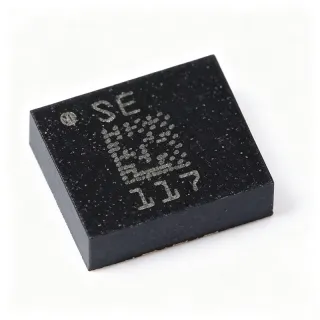
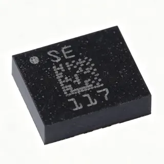
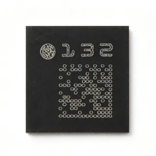
LSM6DSMTR - 6-Axis IMU, ±2/±4/±8/±16 g, ±125/±245/±500/±1000/±2000 dps | STMicroelectronics
MPN: LSM6DSMTR ✓ NakahandaLSM6DSMTR Ulas
An IMU (Inertial Measurement Unit) is a sensor subsystem that fuses multi-axis accelerometer and gyroscope data to deliver orientation, motion, and angular-velocity information. IMUs belong to the broader class of MEMS (micro-electromechanical systems) motion sensors and sit within inertial sensing, a foundational tier of modern sensor signal chains. The LSM6DSMTR is part of ST's iNEMO family - always-on, low-power-on, low-noise sensor modules used in smartphones, wearables, and AR/VR platforms.
Key features include 0.65 mA typical current consumption in high-performance mode, integrated smart FIFO up to 4 kbyte, Android M compliance, a hardware step counter and step detector, and standard I²C/SPI primary digital interfaces. Built-in self-test, a wake-up/free-fall interrupt engine, and a tilt/6D/4D orientation function eliminate the need for host-side algorithm overhead in many use cases. The auxiliary SPI allows an image-stabilization controller to read gyro data without disturbing the main application processor.
The device leverages a CMOS-process MEMS die co-packaged with an ASIC die in a single LGA, providing tight accelerometer/gyroscope cross-axis alignment and factory-calibrated offset/gain. Internal signal conditioning, ADC conversion, and digital filtering yield noise density figures suitable for high-end consumer and prosumer applications where previously only discrete FOG (fiber-optic gyroscope) class performance was acceptable.
Typical applications include smartphone camera OIS/EIS, augmented-reality head tracking, wearable fitness bands, optical image stabilization modules, drone flight controllers, and gesture recognition. The auxiliary SPI + main I²C/SPI dual-bus topology lets a dedicated OIS controller access gyro data while the host application reads accelerometer data over I²C.
When designing with this device, allocate one byte of INT1/INT2 routing for the step counter and another for free-fall/wake-up. Use 100 nF + 1 µF decoupling on VDD and VDDIO, place the part over a keep-out region around the LGA cavity, and respect ST's PCB pad and stencil guidelines (NSMD pads, 0.1 mm via-in-pad optional). This page synthesizes distributor pricing, drop-in alternatives, and practical design notes not found in the manufacturer datasheet.
Mga alternatibo na pwedeng ilagay na LSM6DSMTR — parehas na package, pin-to-pin na katugmang. Hindi kasama ang mga bahagi ng iba't-ibang package na nangangailangan ng pagpapaayos ng PCB.
Variante sa Seri na ito
Katulad na modelo sa serye na katugma sa pagpasok LSM6DSMTR (parehas na form factor at footprint) — pagkakaiba sa Interface, Package, Supply Voltage, Current Consumption (High-Performance Mode), Current Consumption (Normal Mode).
LSM6DSM
✅ Drop-In📋 Alternatibo na Reference (hindi sa katalogo)
LSM6DSMUSTR
✅ Drop-In📋 Alternatibo na Reference (hindi sa katalogo)
LSM6DS3TR
✅ Drop-InMagkontak para sa presyo
Tingnan ang Datasheet →LSM6DSOXTR
✅ Drop-InMagkontak para sa presyo
Tingnan ang Datasheet →LSM6DSLTR
✅ Drop-InMagkontak para sa presyo
Tingnan ang Datasheet →LSM6DSMTR Mga Pinakamataas na Rating at Electrical Characteristics
| Type ng Sensor | Accelerometer, Gyroscope, Temperature (6-axis IMU) |
| Type ng Output | I²C, SPI (primary), SPI (auxiliary OIS) |
| Accelerometer Full-Scale | ±2 g, ±4 g, ±8 g, ±16 g (selectable) |
| Gyroscope Full-Scale | ±125 dps, ±245 dps, ±500 dps, ±1000 dps, ±2000 dps (selectable) |
| Output Data Rate | up to 6.6 kHz |
| Volte ng Pagbibigay | 1.71 V to 3.6 V (VDD), 1.71 V to 3.6 V (VDDIO) |
| Current Consumption (high-performance mode) | 0.65 mA typical |
| Interface | I²C / SPI (main), SPI (auxiliary OIS) |
| FIFO | 4 kbyte smart FIFO |
| Packhaging | 14-pin LGA (3.0 x 2.5 x 0.83 mm) |
| Uri ng Pagpapasok | Surface Mount |
| Temperature na Operasyon | -40 °C to +85 °C |
| Level ng MSL | 3 |
| Built-in Functions | Step counter, free-fall, wake-up, tilt, 6D/4D orientation, self-test |
| Compliance | Android M compliant |
| Tindminan RoHS | Compliant |
Pin Configuration ng LSM6DSMTR
| Pin 1 | VDD — Power supply (1.71 V to 3.6 V) |
| Pin 2 | GND — Ground |
| Pin 3 | RES — Reserved - leave floating or connect to GND per datasheet |
| Pin 4 | VDDIO — I/O supply (1.71 V to 3.6 V) |
| Pin 5 | SDA/SDI/SDO — I²C data / SPI serial data I/O |
| Pin 6 | SCL/SPC — I²C clock / SPI clock |
| Pin 7 | CS — SPI chip select (active low) |
| Pin 8 | INT1 — Programmable interrupt 1 |
| Pin 9 | INT2 — Programmable interrupt 2 |
| Pin 10 | OIS_CS — Auxiliary SPI chip select for OIS |
| Pin 11 | OIS_SCL — Auxiliary SPI clock for OIS |
| Pin 12 | OIS_SDX — Auxiliary SPI serial data |
| Pin 13 | OIS_SDO — Auxiliary SPI serial data output |
| Pin 14 | AUX_ADC — Auxiliary ADC input (gyro temp / external sensor) |
Tipikal na mga Gamit
LSM6DSMTR ay nararapat para sa 6 aplikasyons: Smartphone Camera OIS / EIS, Wearable Fitness Bands & Pedometers, AR / VR Head Tracking, Drone Flight Controller IMU, Gesture Recognition & HMI, Industrial Tilt & Vibration Sensing.
Smartphone Camera OIS / EIS
The LSM6DSMTR is purpose-built for smartphone optical and electronic image stabilization because of its dedicated auxiliary SPI path that lets a dedicated OIS controller read gyroscope data independently from the main application processor. With ±2000 dps full-scale, 6.6 kHz ODR, and low gyro noise density, it delivers the angular-velocity precision needed for closed-loop lens-shift OIS. Unlike general-purpose IMUs that share one bus, the auxiliary SPI removes host-side I/O bottlenecks and jitter in stabilization loops.
Inirekomenda
Wearable Fitness Bands & Pedometers
The LSM6DSMTR's integrated hardware step counter, free-fall, and tilt-detection interrupt engine let wearable fitness bands offload motion classification from the host MCU. Its 0.65 mA high-performance-mode current and sub-µA power-down quiescent current support always-on pedometry without draining small wearable batteries. The 4 kbyte smart FIFO buffers step events during host sleep, eliminating wake-on-every-sample overhead.
Inirekomenda
AR / VR Head Tracking
The LSM6DSMTR's wide gyroscope dynamic range (±2000 dps) and high output data rate (up to 6.6 kHz) suit AR/VR head-mounted display tracking where rotational motion at head-turn speeds must be captured with millisecond latency. The 14-pin LGA is compact enough to fit inside HMD's tight BOM and the high latency reduces perceived motion-to-photon lag. Compared with discrete accelerometer + gyroscope solutions, the integrated IMU simplifies host-side sensor fusion and reduces PCB area.
Inirekomenda
Drone Flight Controller IMU
The LSM6DSMTR serves as the primary 6-DoF inertial sensor in consumer and prosumer drone flight controllers, providing ±16 g acceleration and ±2000 dps rate sensing for attitude estimation loops. The 6.6 kHz ODR enables high-bandwidth PID loops while the auxiliary SPI path can carry OIS data to a secondary camera-gimbal processor. Built-in self-test and factory-calibrated offset/gain simplify field calibration in production drones.
Inirekomenda
Gesture Recognition & HMI
The LSM6DSMTR's wake-up, tilt, 6D/4D orientation, and free-fall interrupt functions make it well suited for gesture-recognition human-machine interfaces such as smart-home controllers, TV remotes, and industrial HMI panels. Hardware-accelerated orientation detection offloads gesture classification from the host MCU, while the 4 kbyte FIFO captures burst gestures without host intervention. The ±16 g range captures sharp tap and flick gestures that lower-g IMUs miss.
Inirekomenda
Industrial Tilt & Vibration Sensing
The LSM6DSMTR is widely deployed in industrial condition-monitoring and tilt-sensing applications such as predictive-maintenance vibration sensors, structural-health monitors, and platform-leveling systems. The wide ±16 g accelerometer range captures vibration peaks while the gyroscope detects rotational oscillation modes. Industrial designers value the LGA-14 industrial-grade temperature rating (-40 °C to +85 °C) and ST's longevity commitment for embedded IMU lines.
Inirekomenda
Buod ng mga Inirekomendang Produkto
Impormasyon ng Talumpati sa Engineering for LSM6DSMTR — ikabit, gabay sa disenyo, at impormasyon ng pagsunod sa kautusan.
Paunawang Hanapin
Ikabit sa Mga Alternatibo
| Parametro | Ito ang Producto | LSM6DSM | LSM6DSMUSTR | LSM6DS3TR | LSM6DSOXTR | LSM6DSLTR |
|---|---|---|---|---|---|---|
| Package | LGA-14 (3.0 x 2.5 x 0.83 mm) | LGA-14 - same | LGA-14 - same | LGA-14 - same | LGA-14 - same | LGA-14 - same |
| Brand | STMicroelectronics | STMicroelectronics | STMicroelectronics | STMicroelectronics | STMicroelectronics | STMicroelectronics |
| Accelerometer Full-Scale | ±2/±4/±8/±16 g | ±2/±4/±8/±16 g | ±2/±4/±8/±16 g | ±2/±4/±8/±16 g | ±2/±4/±8/±16 g | ±2/±4/±8/±16 g |
| Gyroscope Full-Scale | ±125/±245/±500/±1000/±2000 dps | ±125/±245/±500/±1000/±2000 dps | ±125/±245/±500/±1000/±2000 dps | ±125/±245/±500/±1000/±2000 dps | ±125/±245/±500/±1000/±2000 dps | ±125/±245/±500/±1000/±2000 dps |
| Auxiliary OIS SPI | Yes | Yes | Yes | No | No | No |
| Hardware Step Counter | Yes | Yes | Yes | No | Yes (FSM/MLC engine) | Yes |
| FIFO | 4 kbyte | 4 kbyte | 4 kbyte | 8 kbyte | 9 kbyte | 4 kbyte |
| Max ODR | 6.6 kHz | 6.6 kHz | 6.6 kHz | 6.6 kHz | 6.6 kHz | 6.6 kHz |
Pangunahing mga Pagkakaiba
- Only ST 6-axis IMU in LGA-14 with both auxiliary OIS SPI and hardware step counter (kumpara saLSM6DS3TR)
- Smaller process node than legacy LSM6DS3 series (kumpara saLSM6DS3TR)
- Android M compliance out-of-the-box (kumpara saLSM6DSOXTR)
Talaan ng Disenyo
Per the ST AN5040 application note, place 100 nF + 1 µF decoupling capacitors as close as possible to the VDD and VDDIO pins, with the smallest capacitor nearest the LGA land. Maintain a keep-out region under the LGA cavity and route the auxiliary OIS SPI traces away from the main SPI bus. Use NSMD PCB pads with the ST-recommended land pattern and via-in-pad for the GND thermal pad to ensure proper mechanical and thermal bonding of the LGA.
Do not connect the RES pin to anything other than GND or floating per datasheet. Incorrect RES handling can prevent the device from responding to I²C/SPI commands. Always perform a soft-reset (CTRL_REG3 register) after power-up and verify the WHO_AM_I register returns 0x6A before configuring the sensor. Note that the auxiliary OIS SPI uses a separate register bank from the main SPI - reading OIS data through the main SPI returns incorrect values.
Keep I²C lines (SDA/SCL) below 100 mm and add 4.7 kΩ pull-ups to VDDIO. For SPI, place a 100 Ω series resistor near the host MCU on SPC, SDI, and SDO to dampen reflections. The auxiliary OIS SPI traces should be length-matched within 1 mm if running above 5 MHz. Add a 10 kΩ pull-down on CS to ensure the IMU boots in I²C mode by default if the host does not drive CS immediately.
Impormasyon ng Pagsunod sa Kautusan
RoHS and REACH compliant per STMicroelectronics product environmental compliance page. Not AEC-Q100 qualified - consumer/industrial grade. Choose ASM330LHH or ISM330DHCX for AEC-Q100 automotive applications.