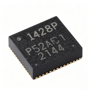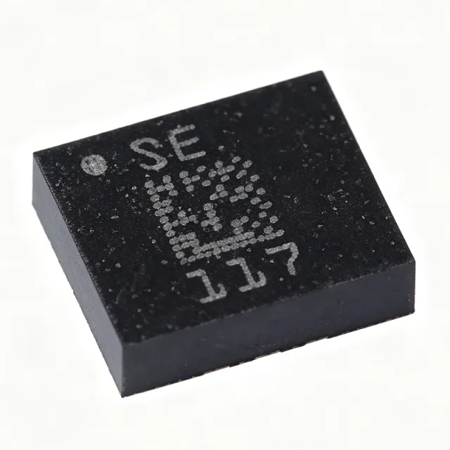
LSM6DS3TR - 3D Accelerometer & Gyroscope | STMicroelectronics
MPN: LSM6DS3TR ✓ Active| Qty | Unit Price | Extended |
|---|---|---|
| 1 | $1.83 | $1.83 |
| 10 | $1.3 | $13.00 |
| 100 | $1.23 | $123.00 |
| 500 | $1.16 | $580.00 |
| 1,000 | $1.11 | $1,110.00 |
| 2,500 | $1.08 | $2,700.00 |
| 5,000 | $1.05 | $5,250.00 |
LSM6DS3TR Overview
An inertial measurement unit (IMU) is a sensor that combines an accelerometer and a gyroscope to measure linear acceleration and angular velocity, respectively. The LSM6DS3TR integrates both sensors in a single package, providing a complete motion-sensing solution. In the system hierarchy, an IMU is a type of motion sensor, which falls under the broader category of sensors, and ultimately within the domain of microelectromechanical systems (MEMS). This integration reduces board space, simplifies design, and improves reliability compared to discrete solutions.
Key features include a 16-bit data output for both accelerometer and gyroscope, an embedded 9kB FIFO for data buffering, and advanced motion detection functions such as free-fall, wake-up, single/double-tap, and 6D/4D orientation detection. The device also features a programmable interrupt generator, an embedded temperature sensor, and a low-power mode with a typical current consumption of 0.9 mA in normal mode and 1.25 mA in high-performance mode. The LSM6DS3TR supports a wide operating temperature range of -40°C to +85°C, making it suitable for harsh environments.
Technically, the LSM6DS3TR utilizes a MEMS capacitive sensing element for both acceleration and angular rate, with a dedicated ASIC for signal conditioning and digital conversion. The device includes a smart FIFO that can be configured to store up to 9kB of data, reducing host processor load. The I2C address is 0x6A (default) or 0x6B (alternate), selectable via the SA0 pin. The SPI interface supports up to 10 MHz clock frequency. The device is compliant with RoHS and REACH directives, and it is halogen-free.
Typical applications include motion-activated user interfaces, gaming and virtual reality systems, industrial automation, robotics, and IoT devices. The LSM6DS3TR is particularly suited for battery-powered devices due to its low power consumption and flexible power modes. In a smartphone, it enables screen rotation and step counting; in industrial equipment, it provides vibration monitoring and tilt sensing.
When designing with the LSM6DS3TR, ensure proper decoupling of the power supply with a 100nF capacitor close to the VDD pin, and route the I2C/SPI lines with appropriate pull-up resistors. The device's interrupt pins can be configured to wake the host processor only when motion is detected, optimizing system power. This page synthesizes distributor pricing, drop-in alternatives, and practical design notes not found in the ST datasheet.
Drop-in alternatives for LSM6DS3TR — same package, pin-to-pin compatible. Different-package parts requiring PCB rework are excluded.
Variants in this series
Same-series models that are drop-in compatible with LSM6DS3TR (same form factor and footprint) — differing in Interface, Package, Current Consumption (Normal Mode), Output Data Rate (ODR), Current Consumption (High-Performance Mode).
Quick Comparison Tool — Select alternative parts for side-by-side comparison:
LSM6DS3TR-C
✓ In Stock
$0.875 / Unit
View Datasheet →LSM6DS3
📋 Reference alternative (not in catalog)
LSM6DSO
📋 Reference alternative (not in catalog)
LSM6DS3TR Maximum Ratings & Electrical Characteristics
| Supply Voltage | 1.71 V to 3.6 V |
| Accelerometer Full-Scale Range | ±2/±4/±8/±16 g |
| Gyroscope Full-Scale Range | ±125/±245/±500/±1000/±2000 dps |
| Accelerometer Sensitivity | 0.061 mg/LSB (at ±2 g) |
| Gyroscope Sensitivity | 4.375 mdps/LSB (at ±125 dps) |
| Output Data Rate (ODR) | 1.6 Hz to 6.66 kHz (accel), 12.5 Hz to 6.66 kHz (gyro) |
| Interface | I2C (up to 400 kHz), SPI (up to 10 MHz) |
| FIFO Size | 9 kB |
| Current Consumption (Normal Mode) | 0.9 mA |
| Current Consumption (High-Performance Mode) | 1.25 mA |
| Operating Temperature Range | -40°C to +85°C |
| Package | LGA-14 (2.5 x 3.0 x 0.83 mm) |
| Mounting Type | Surface Mount |
| RoHS Status | Compliant |
| REACH Status | Compliant |
| Halogen-Free | Yes |
LSM6DS3TR Pin Configuration
| Pin 1 | VDD — Power supply (1.71V to 3.6V) |
| Pin 2 | GND — Ground |
| Pin 3 | SCL/SPC — I2C clock / SPI clock |
| Pin 4 | SDA/SDI — I2C data / SPI data input |
| Pin 5 | SA0/SDO — I2C address select / SPI data output |
| Pin 6 | CS — Chip select (active low) |
| Pin 7 | INT1 — Interrupt 1 (programmable) |
| Pin 8 | INT2 — Interrupt 2 (programmable) |
| Pin 9 | RES — Reserved (do not connect) |
| Pin 10 | RES — Reserved (do not connect) |
| Pin 11 | RES — Reserved (do not connect) |
| Pin 12 | RES — Reserved (do not connect) |
| Pin 13 | GND — Ground |
| Pin 14 | GND — Ground |
Typical Applications
LSM6DS3TR is suitable for 6 applications: Wearable Fitness Trackers, Smartphone Motion Sensing, Industrial Vibration Monitoring, Gaming and Virtual Reality, IoT Smart Home Devices, Robotics and Drones.
Wearable Fitness Trackers
The LSM6DS3TR is ideal for wearable fitness trackers due to its low power consumption (0.9 mA in normal mode) and embedded step counter. In a typical fitness tracker, the LSM6DS3TR is placed on the main PCB and connected via I2C to the microcontroller. The device's pedometer function counts steps in real-time, and the 9kB FIFO buffers data to reduce host wake-ups. The accelerometer's ±16 g range captures high-impact activities, while the gyroscope tracks motion orientation. The low-power mode extends battery life, enabling continuous monitoring for days. Compared to discrete sensors, the integrated IMU reduces board space and simplifies design, making it ideal for compact wearables.
Recommended
Smartphone Motion Sensing
The LSM6DS3TR is widely used in smartphones for screen rotation, step counting, and gesture recognition. In a smartphone, the LSM6DS3TR is mounted near the center of the PCB to minimize mechanical stress. The device's 6D orientation detection enables automatic screen rotation, while the gyroscope provides smooth motion tracking for gaming and augmented reality. The I2C interface connects to the application processor, and the interrupt pins wake the processor only when motion is detected, saving power. The device's small LGA-14 package (2.5 x 3.0 mm) fits into the tight PCB layout of modern smartphones. The high ODR (up to 6.66 kHz) ensures low latency for real-time applications.
Recommended
Industrial Vibration Monitoring
The LSM6DS3TR is suitable for industrial vibration monitoring due to its wide full-scale range (±16 g) and high ODR (up to 6.66 kHz). In a typical predictive maintenance system, the LSM6DS3TR is attached to rotating machinery to measure vibration signatures. The device's free-fall and wake-up functions can trigger alerts when abnormal vibrations are detected. The SPI interface allows high-speed data streaming to a host controller for real-time analysis. The industrial temperature range (-40°C to +85°C) ensures reliable operation in harsh factory environments. The embedded FIFO can store vibration data for post-processing, reducing the need for continuous host communication.
Recommended
Gaming and Virtual Reality
The LSM6DS3TR is ideal for gaming and virtual reality (VR) headsets due to its high ODR and low latency. In a VR headset, the LSM6DS3TR tracks head movements with the gyroscope, providing accurate orientation data for immersive experiences. The accelerometer detects linear motion, enabling gesture-based controls. The device's SPI interface supports high-speed data transfer, and the interrupt pins can be used to synchronize with the rendering engine. The low power consumption is critical for battery-powered VR controllers. The device's small size allows integration into compact headset designs without compromising performance.
Recommended
IoT Smart Home Devices
The LSM6DS3TR is used in IoT smart home devices for motion detection, tilt sensing, and security monitoring. In a smart thermostat, the LSM6DS3TR detects occupancy by sensing vibrations and movement. The device's wake-up function allows the system to remain in low-power mode until motion is detected, extending battery life. The I2C interface connects to a low-power MCU, and the embedded FIFO buffers data to reduce communication overhead. The device's small package and low cost make it ideal for mass-produced IoT devices. The wide supply voltage range (1.71V to 3.6V) allows direct connection to battery-powered systems.
Recommended
Robotics and Drones
The LSM6DS3TR is used in robotics and drones for attitude estimation and stabilization. In a drone, the LSM6DS3TR provides angular rate and acceleration data to the flight controller, enabling precise attitude control. The device's high ODR (up to 6.66 kHz) ensures fast response to control commands, and the wide full-scale range (±16 g) accommodates aggressive maneuvers. The SPI interface allows high-speed data transfer to the flight controller, and the interrupt pins can trigger emergency stabilization. The device's small size and low weight are critical for drone payload constraints. The industrial temperature range ensures reliable operation in outdoor environments.
Recommended
Recommended Products Summary
Engineering reference data for LSM6DS3TR — comparison, design guidance, and compliance information.
Selection Guide
Comparison with Alternatives
| Parameter | This Product | LSM6DS3 | LSM6DS3TR-C | LSM6DSO |
|---|---|---|---|---|
| Package | LGA-14 | LGA-14 - same | LGA-14 - same | LGA-14 - same |
| Supply Voltage | 1.71V to 3.6V | 1.71V to 3.6V | 1.71V to 3.6V | 1.71V to 3.6V |
| Accelerometer Full-Scale | ±2/±4/±8/±16 g | ±2/±4/±8/±16 g | ±2/±4/±8/±16 g | ±2/±4/±8/±16 g |
| Gyroscope Full-Scale | ±125/±245/±500/±1000/±2000 dps | ±125/±245/±500/±1000/±2000 dps | ±125/±245/±500/±1000/±2000 dps | ±125/±245/±500/±1000/±2000 dps |
| Output Data Rate (Max) | 6.66 kHz | 6.66 kHz | 6.66 kHz | 6.66 kHz |
| FIFO Size | 9 kB | 9 kB | 9 kB | 3 kB |
| Current Consumption (Normal) | 0.9 mA | 0.9 mA | 0.9 mA | 0.55 mA |
| Noise (Accel, ±2g) | 90 µg/√Hz | 90 µg/√Hz | 130 µg/√Hz | 60 µg/√Hz |
| Automotive Grade | No | No | No | No |
Key Differentiators
- Larger FIFO size (9 kB) compared to LSM6DSO (3 kB) (vs LSM6DSO)
- Lower cost than LSM6DSO (vs LSM6DSO)
- Higher noise performance than LSM6DS3TR-C (vs LSM6DS3TR-C)
Design Notes
Place a 100nF ceramic capacitor as close as possible to the VDD pin and a 1uF capacitor in parallel for bulk decoupling. The LSM6DS3TR operates from 1.71V to 3.6V, so ensure the supply is stable and free of noise, especially in battery-powered designs. A low-dropout regulator (LDO) is recommended to provide a clean supply if the input voltage varies.
Route the I2C/SPI lines with controlled impedance and keep them short to minimize noise. Use pull-up resistors (typically 4.7kΩ) on the I2C lines. The CS pin must be tied high for I2C mode or low for SPI mode. Ensure the SA0 pin is set to the desired I2C address before power-up. The LGA-14 package has a 0.5mm pitch, so use a stencil with appropriate aperture for soldering.
Do not leave the INT1 and INT2 pins floating; configure them as push-pull or open-drain with pull-ups as needed. The reserved pins (9-12) must not be connected to any trace or via. Avoid placing the sensor near high-frequency switching components or strong magnetic fields, as this can affect measurement accuracy. Ensure the device is mounted flat to avoid mechanical stress that could cause offset errors.
Compliance Information
RoHS and REACH compliant per STMicroelectronics product page. Not AEC-Q100 qualified - for automotive, consider LSM6DSO with AEC-Q100 option.