ESD1P0RFS - 1 pF 2-Channel RF ESD Diode | Infineon
MPN: ESD1P0RFS ✗ Son Kullanım ZamanıESD1P0RFS Genel Bakış
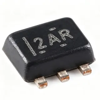
What is an RF ESD protection diode? It is a transient-voltage-suppressor diode designed to divert electrostatic discharge energy away from a sensitive circuit while introducing very little capacitance into the protected signal. ESD1P0RFS is a low-capacitance, multi-line protection device, placing it in the interface-protection hierarchy between passive circuit protection and the protected RF or high-speed interface.
The principal feature is the 1 pF typical capacitance, which helps preserve signal integrity on RF and high-speed lines. The verified data identifies four RF ESD protection diodes in the six-terminal device and describes use for one protected signal line in an anti-parallel configuration. The application example also notes that a protected line may carry superimposed DC voltage up to ±2 × VF, where VF is the diode forward voltage.
Technically, the device combines low capacitance with high transient-energy handling. Its 2-channel arrangement allows two signal conductors or related interface lines to be protected in a compact footprint. The 70 V rating reported for the related distributor listing describes the device category and ordering context, while the verified series document supplies the application example and protection references.
Typical uses include RF antenna inputs, GPS, HDMI, Ethernet interfaces, communications equipment, and ultra-high-speed data-line protection. In these systems, capacitance affects edge bandwidth, insertion loss, and signal integrity; a 1 pF device is selected when the interface must remain responsive while exposed to ESD events.
PCB placement is important. Place the protection device close to the connector or board entry, connect the protected line through the device as shown in the manufacturer application example, and keep high-current surge paths away from sensitive logic. Verify the complete interface against the applicable system ESD, EFT, and surge requirements rather than relying only on the device rating.
This page consolidates the verified Infineon series documentation, distributor information, technical parameters, protection standards, and design considerations for faster component selection and PCB implementation.
Drop-in alternatifler için ESD1P0RFS — aynı paket, pin-başına uyumlu. PCB yeniden montajı gerektiren farklı paket bileşenleri dışlanmıştır.
Bu Serideki Variantlar
Yedek parça uyumlu olan aynı serideki modeller ESD1P0RFS (aynı form faktörü ve ayağa oturma) — farklı olan Application Configuration, Device Type, Package, Surge Compliance.
ESD1P0RFW
✅ YerleştirmeFiyat için iletişime geçin
Veri Şablonunu Görüntüle →ESD1P0RFS Maksimum Değerlendirmeler & Elektriksel Özellikler
| Device Type | RF ESD protection diode / transient voltage suppressor diode |
| Number of Channels | 2 channels |
| Number of Diodes | 4 diodes |
| Typical Capacitance | 1 pF |
| ESD Protection, Contact | ±20 kV |
| ESD Standard | IEC61000-4-2 |
| EFT Standard | IEC61000-4-4 |
| EFT Waveform | A, 5/50 ns |
| Surge Standard | IEC61000-4-5 |
| Surge Waveform | A, 8/20 µs |
| Surge Compliance | 10 A |
| Pin Sayısı | 6 pins |
| Terminal Position | Dual |
| Terminal Form | Gull wing |
| Montaj Türü | Surface mount |
| Package Shape | Rectangular |
| Application Configuration | 1 protected signal line in low-capacitance anti-parallel configuration |
| Allowed Superimposed DC Voltage | Up to ±2 × VF |
| Manufacturer | Infineon Technologies AG |
ESD1P0RFS rectangular Pin Yapısı Kılavuzu
ESD1P0RFS (rectangular paket) için pin yapısı. Bu güç cihazı gate, drain ve kaynak terminal özelliklerlidir. Polarizasyonlu paketler için, doğru pin 1 yönlendirme ve ayak detayları için üretici veri kitapçığını referans alın. Orta uygulamalar arasında güç besleme tasarımı, motor kontrolü ve yük değiştirme bulunur.

Ayrıntılı pin çıkış verisi mevcut değil: ESD1P0RFS.
Aşağıdaki veri sayfası tam pin konfigürasyonu için.
Tipik Uygulamalar
ESD1P0RFS için uygundur 6 uygulamas: RF Antenna Input Protection, GPS and Navigation Interfaces, HDMI High-Speed Interface Protection, Ethernet Network Port Protection, Ultra-High-Speed Data-Line Protection, Communications Equipment ESD Protection.
RF Antenna Input Protection
The Infineon ESD1P0RFS fits RF antenna-entry protection because its 1 pF typical capacitance minimizes loading on high-frequency signal paths while providing ±20 kV contact ESD protection. Place the diode close to the antenna connector and route the protected conductor through the manufacturer’s anti-parallel arrangement. This helps protect the receiver or RF front end from electrostatic discharge without intentionally adding a large shunt capacitance. The design must still account for connector geometry, RF return paths, and the actual antenna frequency range.
Önerilen
GPS and Navigation Interfaces
ESD1P0RFS is appropriate for GPS or navigation signal protection where low capacitance helps preserve the protected line’s RF behavior. The verified Infineon documentation associates the ESD1P0RF family with GPS applications and specifies 1 pF typical capacitance. Position the protection device near the connector entry and use a controlled ground return so the transient current does not flow through sensitive receiver traces. Validate the complete interface for RF loss, ESD immunity, and system-level surge requirements.
Önerilen
HDMI High-Speed Interface Protection
The 1 pF typical capacitance of ESD1P0RFS makes it a candidate for ESD protection on suitable HDMI or other ultra-high-speed data lines. It helps limit parasitic loading while the device diverts ESD transients away from downstream logic. The correct channel assignment and connection must follow the six-terminal package drawing and the interface’s protection architecture. Because the verified data does not provide every pin-level connection or channel-bandwidth detail, engineers should confirm both with the current Infineon datasheet.
Önerilen
Ethernet Network Port Protection
ESD1P0RFS can be evaluated for Ethernet or other communications interfaces where low capacitance and transient protection are both important. The verified Infineon family page identifies Ethernet-related applications, and the target device provides 1 pF typical capacitance with ±20 kV contact ESD protection. Place the diode at the external interface boundary, maintain a short surge return, and verify line impedance and insertion loss after adding the protection path. A system-level qualification remains necessary.
Önerilen
Ultra-High-Speed Data-Line Protection
For ultra-high-speed data lines, ESD1P0RFS offers a compact, low-capacitance protection solution with 2-channel capability and 1 pF typical capacitance. The protection device should be close to the connector so the vulnerable PCB segment is minimized. Designers must balance capacitance, data-rate margin, return-path continuity, and the IEC61000-4-2, IEC61000-4-4, and IEC61000-4-5 test objectives. Use the manufacturer’s application example as the starting point, then validate with the finished board.
Önerilen
Communications Equipment ESD Protection
ESD1P0RFS is suited to communications equipment exposed to user contact or cable-transient ESD events. Its 1 pF typical capacitance is intended to preserve signal behavior in RF and high-speed interface sections, while the ±20 kV contact rating provides a defined device-level protection target. Integrate the diode close to the connector, provide a low-impedance return, and avoid routing transient current through sensitive analog or digital areas. The final device choice should be checked against the enclosure, grounding, and system test standard.
Önerilen
Mühendislik referans verileri: ESD1P0RFS — karşılaştırma, tasarım rehberi ve uyumluluk bilgileri.
Seçim Kılavuzu
Alternatiflerle Karşılaştırma
| Parametre | Bu Ürün | ESD1P0RFW |
|---|---|---|
| Package | 6-pin surface-mount gull-wing package | 6-pin surface-mount package; exact package designation requires datasheet confirmation |
| Brand | Infineon | Infineon |
| Channel Count | 2 channels | 1 channel |
| Typical Capacitance | 1 pF | 1 pF |
| Contact ESD Protection | ±20 kV | ±20 kV |
| Surge Compliance | 10 A | 10 A |
| Application Class | RF ESD protection diode | RF ESD protection diode |
| Protection Standards | IEC61000-4-2, IEC61000-4-4, IEC61000-4-5 | IEC61000-4-2 and related transient-protection family ratings |
Ana Farklılayıcılar
- Two-channel protection in one device (karşılaştırma:ESD1P0RFW)
- Matched low-capacitance RF protection (karşılaştırma:ESD1P0RFW)
- Defined transient-protection coverage (karşılaştırma:ESD1P0RFW)
Tasarım Notları
Place ESD1P0RFS at the interface boundary, immediately next to the external connector or cable entry. Route the protected signal through the device according to the Infineon application example and keep the ESD current return short and continuous. A long unprotected trace between the connector and diode leaves the downstream circuit exposed to the transient event.
Use the 1 pF typical capacitance as the initial signal-integrity selection value, then verify the complete interface with the actual connector, trace geometry, receiver impedance, and target data rate. Confirm insertion loss, edge-rate degradation, and return-path behavior on the finished PCB rather than assuming the device capacitance alone guarantees compliance.
Do not substitute ESD1P0RFW without checking channel count and PCB connectivity. The verified family data identifies ESD1P0RFS as 2-channel and ESD1P0RFW as 1-channel, even though both are described with approximately 1 pF capacitance and ±20 kV contact ESD protection. Also verify the six-terminal pin assignment from the official datasheet before fabrication.
Uyumluluk Bilgisi
The verified data references IEC61000-4-2, IEC61000-4-4, and IEC61000-4-5 transient-protection tests, but it does not state RoHS, REACH, lead-free, halogen-free, AEC-Q100, or conflict-minerals status.