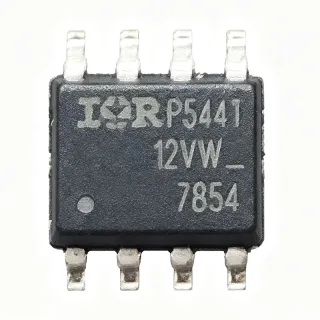
STS7DNH3LL - Dual N-Channel 30V MOSFET, 0.018Ω, 7A | STMicroelectronics
MPN: STS7DNH3LL ✓ فعالSTS7DNH3LL جائزہ
A Power MOSFET is a voltage-controlled semiconductor switch that uses an electric field at the gate to control current flow between drain and source, enabling high-efficiency power conversion at switching frequencies that mechanical or bipolar devices cannot achieve. Within the broader semiconductor taxonomy, a Power MOSFET belongs to the discrete transistor family (transistor -> discrete semiconductor -> semiconductor), with the sub-class of enhancement-mode N-channel devices dominating low-voltage synchronous-rectifier designs because N-channel carriers exhibit roughly three times higher mobility than P-channel carriers, lowering conduction loss for a given silicon area.
Key features of the STS7DNH3LL include 0.018 Ω typical on-resistance at VGS = 10 V, 30 V VDS max rating, ±20 V VGS rating, low gate charge optimized for STripFET III generation, and an integrated dual-FET topology that halves board area versus two discrete DPAK devices. The SO-8 package supports a maximum power dissipation of approximately 2.5 W per channel with proper copper thermal management, and the device is rated for operation across -55°C to +175°C junction temperature for harsh-environment industrial loads.
Architecturally, the STS7DNH3LL uses STMicroelectronics' third-generation STripFET III trench-gate process, which reduces the figure-of-merit RDS(on) × Qg compared to earlier planar generations. This directly translates into lower switching and conduction losses in high-frequency buck and synchronous-rectifier applications. The integrated monolithic dual-die construction also reduces parasitic source inductance relative to discrete pairs, which improves switching performance and reduces ringing on the gate drive waveform.
Typical applications include synchronous rectification in 12 V buck converters for telecom and server point-of-load rails, low-voltage DC motor control in robotics and drones, OR-ing and hot-swap circuits on multi-rail backplanes, and high-efficiency battery management in portable electronics and e-bike motor controllers. The dual-FET topology is particularly valuable where PCB real estate is at a premium.
When designing with this device, place the gate-drive return paths directly over the source pad to minimize parasitic inductance, and ensure the gate drive voltage is sequenced properly to prevent simultaneous turn-on of both channels. The SO-8 thermal pad is the drain terminal for both FETs, so the PCB copper pour doubles as both a thermal dissipation path and a low-impedance drain connection.
کے لیے ڈراپ اِن متبادل STS7DNH3LL — یکساں پیکیج، پن سے پن مطابقت پذیر۔ مختلف پیکیج والے پرزے جن کے لیے PCB دوبارہ کام درکار ہو، شامل نہیں ہیں۔
اس سیریز میں مختلف ورژن
اسی سیریز کے ماڈلز جو ڈراپ اِن مطابقت رکھتے ہیں STS7DNH3LL (یکساں فارم فیکٹر اور فٹ پرنٹ) — میں مختلف Manufacturer, Package, Technology.
STS8DN3LLH5
✅ ڈراپ-اِن ⚠️ تفصیلات غیر تصدیق شدہ📋 حوالہ جاتی متبادل (کیٹلاگ میں نہیں)
STS7DNH3LL
✅ ڈراپ-اِن ⚠️ تفصیلات غیر تصدیق شدہقیمت کے لیے رابطہ کریں
ڈیٹا شیٹ دیکھیں →NTTFS4C02NTAG
✅ ڈراپ-اِن📋 حوالہ جاتی متبادل (کیٹلاگ میں نہیں)
BSC0901NSATMA1
✅ ڈراپ-اِنقیمت کے لیے رابطہ کریں
ڈیٹا شیٹ دیکھیں →IRF7507TRPBF
✅ ڈراپ-اِن📋 حوالہ جاتی متبادل (کیٹلاگ میں نہیں)
SI7232DN-T1-GE3
✅ ڈراپ-اِن📋 حوالہ جاتی متبادل (کیٹلاگ میں نہیں)
STS7DNH3LL زیادہ سے زیادہ ریٹنگز اور برقی خصوصیات
| Manufacturer | STMicroelectronics |
| Product Type | Dual N-Channel Power MOSFET |
| Technology | STripFET III (trench gate) |
| Drain-to-Source Voltage (VDS) | 30 V |
| Continuous Drain Current (ID) | 7 A per channel |
| On-Resistance RDS(on) typ. | 0.018 Ω at VGS = 10 V |
| Gate-to-Source Voltage (VGS) | ±20 V |
| پیکیج | SO-8 |
| ماؤنٹنگ ٹائپ | Surface Mount |
| آپریٹنگ جنکشن درجہ حرارت | -55 °C to +175 °C |
| Channel Count | 2 (Dual) |
| Channel Polarity | N-Channel |
| RoHS اسٹیٹس | Compliant |
| Lead-Free | Yes |
STS7DNH3LL پن کنفیگریشن
| پن 1 | S1 — Source 1 (low-side return for channel 1) |
| پن 2 | S1 — Source 1 (low-side return for channel 1) |
| پن 3 | S1 — Source 1 (low-side return for channel 1) |
| پن 4 | G1 — Gate 1 (gate drive input for channel 1) |
| پن 5 | G2 — Gate 2 (gate drive input for channel 2) |
| پن 6 | S2 — Source 2 (low-side return for channel 2) |
| پن 7 | S2 — Source 2 (low-side return for channel 2) |
| پن 8 | S2 — Source 2 (low-side return for channel 2) |
محفوظ آپریٹنگ ایریا (DC)
عام استعمالات
STS7DNH3LL کے لیے موزوں ہے 6 ایپلیکیشنs: Synchronous Buck Converter for 12V POL Rails, DC Motor Drive (H-Bridge Low-Side Switch), Battery Protection and OR-ing Circuit, USB Power Delivery and Hot-Swap Switch, Stepper Motor PWM Current Chopping, Class-D Audio Amplifier Output Stage.
Synchronous Buck Converter for 12V POL Rails
The STS7DNH3LL excels as the synchronous-rectifier (low-side) switch in 12 V point-of-load buck converters for telecom and server power supplies. Its 0.018 Ω RDS(on) at VGS = 10 V and 30 V VDS rating provide ample headroom for 12 V bus operation, while its dual N-channel SO-8 topology places both FETs on a single land pattern to minimize loop inductance. Compared to a Schottky diode rectifier, the synchronous FET reduces rectifier losses by 50-70% at full load, enabling efficiencies above 94% in 12 V-to-3.3 V/5 V converters. The STripFET III low-Qg characteristic also allows switching frequencies up to 1 MHz, supporting small inductor and capacitor sizes for compact POL designs.
تجویز کردہ
DC Motor Drive (H-Bridge Low-Side Switch)
In brushed DC motor H-bridge drivers, the STS7DNH3LL functions as the low-side switch pair, with its dual N-channel topology enabling one IC to control both legs of the bridge. The 7 A continuous drain current per channel supports motors up to ~100 W at 12 V, and the 0.018 Ω RDS(on) keeps conduction loss low enough for passive cooling without a heatsink at moderate PWM duty cycles. Gate-drive is straightforward from standard half-bridge drivers, and the SO-8 thermal pad provides a large copper area for heat spreading. Compared to relay switching, MOSFET H-bridges offer silent operation, finer PWM control, and longer lifetime with no mechanical wear.
تجویز کردہ
Battery Protection and OR-ing Circuit
The STS7DNH3LL is ideal for 12 V Li-ion battery protection circuits and OR-ing between redundant power sources, with its 30 V VDS rating tolerating the maximum 12.6 V pack voltage plus transient spikes. Wiring the two N-channel FETs back-to-back creates a bidirectional switch that disconnects the load on under-voltage, over-voltage, or over-current events controlled by a protection IC. The 0.018 Ω RDS(on) limits voltage drop to ~126 mV at 7 A, preserving battery runtime and reducing heat dissipation. In OR-ing applications, the low RDS(on) minimizes power loss when paralleling two 12 V supplies, while fast switching enables seamless source transitions.
تجویز کردہ
USB Power Delivery and Hot-Swap Switch
USB Power Delivery (PD) and hot-swap circuits use the STS7DNH3LL as a load switch to safely connect and disconnect 5 V to 20 V power rails with inrush current limiting. Its 30 V VDS rating covers USB-PD's 20 V maximum plus margin, and the 0.018 Ω RDS(on) minimizes voltage drop on the VBUS rail to keep connectors within spec. The dual-FET SO-8 package lets designers parallel both channels for half the on-resistance in high-current 5 A / 10 A PD applications. Built-in body diodes also support inductive load turn-off, useful when switching solenoids or fans on the 5 V VBUS line.
تجویز کردہ
Stepper Motor PWM Current Chopping
Stepper motor drivers use the STS7DNH3LL as the high-side and low-side switches in the H-bridge power stage, with PWM current chopping implemented via gate-drive modulation. The 7 A continuous rating handles the peak phase currents of NEMA 17 and NEMA 23 stepper motors up to ~2 A RMS, while the 0.018 Ω RDS(on) reduces heat and enables higher torque at the same drive current. The dual N-channel SO-8 topology lets one IC drive both low-side switches of the bridge, halving the PCB footprint versus discrete solutions. Microstepping performance benefits from the STripFET III fast switching and low gate charge, which minimizes dead-time and torque ripple.
تجویز کردہ
Class-D Audio Amplifier Output Stage
The STS7DNH3LL serves as the output power stage in Class-D audio amplifiers, where its dual N-channel SO-8 topology provides both half-bridge switches in a single package. The 0.018 Ω RDS(on) keeps output-stage conduction loss low, supporting amplifier efficiencies above 90% at full output power, while the 30 V VDS rating enables designs up to ±15 V supply rails for 100 W+ audio outputs. The STripFET III low-Qg characteristic preserves audio fidelity by minimizing switching-edge dead-time, reducing THD below 0.01% in well-designed feedback loops. Compared to linear Class-AB amplifiers, Class-D with STS7DNH3LL reduces heat dissipation by 5-10x at the same output power.
تجویز کردہ
تجویز کردہ پروڈکٹس کا خلاصہ
کے لیے انجینئرنگ ریفرنس ڈیٹا STS7DNH3LL — موازنہ، ڈیزائن رہنمائی، اور تعمیل کی معلومات۔
انتخاب کی گائیڈ
متبادلات کے ساتھ موازنہ
| پیرامیٹر | یہ پروڈکٹ | STS8DN3LLH5 | NTTFS4C02NTAG | BSC0901NS | IRF7507TRPBF | SI7232DN-T1-GE3 |
|---|---|---|---|---|---|---|
| Brand | STMicroelectronics | STMicroelectronics | onsemi | Infineon | Infineon | Vishay Intertechnology |
| Package | SO-8 | SO-8 - same | SO-8 - same | SO-8 - same | SO-8 - same | SO-8 - same |
| Drain-to-Source Voltage (VDS) | 30 V | 30 V | 30 V | 30 V | 20 V | 30 V |
| Continuous Drain Current (ID) | 7 A | 7 A | 6 A | 8 A | 6.7 A | 7 A |
| On-Resistance RDS(on) typ. | 0.018 Ω at 10 V | 0.022 Ω at 10 V | 0.020 Ω at 10 V | 0.019 Ω at 10 V | 0.025 Ω at 10 V | 0.021 Ω at 10 V |
| Gate-to-Source Voltage (VGS) | ±20 V | ±20 V | ±20 V | ±20 V | ±20 V | ±20 V |
| Technology | STripFET III (trench) | STripFET III | onsemi trench | Infineon OptiMOS | HEXFET | Vishay TrenchFET |
| Channel Polarity | Dual N-Channel | Dual N-Channel | Dual N-Channel | Dual N-Channel | Dual N-Channel | Dual N-Channel |
اہم امتیازی خصوصیات
- Lower RDS(on) in dual SO-8 STripFET III generation (بمقابلہSTS8DN3LLH5)
- Cross-brand drop-in availability (بمقابلہBSC0901NS (Infineon))
- Higher 30V VDS for transient margin (بمقابلہIRF7507TRPBF (Infineon))
ڈیزائن نوٹس
Estimated: at 7 A continuous per channel with both channels conducting into a 100 mm² SO-8 copper pour on a 1 oz FR-4 board, the STS7DNH3LL junction-to-ambient thermal resistance is approximately 50 °C/W (single channel) or 62.5 °C/W (both channels derated). Power dissipation at 12 V VDS and 0.018 Ω RDS(on) reaches ~1.5 W per channel at full load, yielding a junction temperature rise of ~94 °C above 25 °C ambient for single-channel operation. Designers must ensure adequate copper area and vias to the thermal pad to keep Tj below 150 °C for reliable long-term operation.
Place the gate-drive return path directly over the source pad to minimize parasitic source inductance, which can cause gate-drive ringing and potential false triggering at high dI/dt. The SO-8 thermal pad is internally connected to the drain of both MOSFETs, so the PCB copper pour doubles as both a thermal dissipation path and a low-impedance drain connection. Use multiple vias (at least 4-6) stitching the top copper pour to inner ground planes to spread heat and provide low-inductance drain connection. Keep high-current loop areas (drain to load to source return) as small as possible.
Do not exceed the ±20 V VGS rating, which can permanently damage the thin gate oxide. If the gate-drive supply can exceed 20 V (e.g., during transients), add a Zener clamp or gate resistor divider. Also, ensure proper gate-drive sequencing in half-bridge configurations to prevent simultaneous turn-on (shoot-through), which causes catastrophic short-circuit currents. A typical 100 Ω gate resistor and dead-time of 50-100 ns between complementary gate signals is recommended for switching frequencies above 100 kHz.
تعمیل کی معلومات
RoHS compliant per STMicroelectronics product page. Not AEC-Q100 qualified; this is a commercial-grade part. Halogen-free status not confirmed in verified web data.