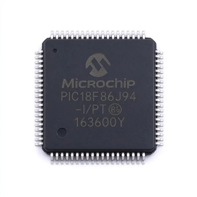
PIC18F86J55T-I/PT - 96KB Flash USB MCU 8-Bit 48MHz TQFP-80
MPN: PIC18F86J55T-I/PT ✓ Hoạt động| Số lượng | Giá đơn vị | Phụ |
|---|---|---|
| 1 | $11.25 | $11,25 |
| 10 | $8.125 | $81,25 |
| 100 | $7.1875 | $718,75 |
| 500 | $6.875 | $3.437,50 |
| 1.000 | $6.5625 | $6.562,50 |
PIC18F86J55T-I/PT Tóm tắt
A microcontroller (MCU) is an integrated circuit containing a CPU, memory, and programmable peripherals. The PIC18J family is built on an enhanced Harvard architecture with a RISC-style instruction set, providing deterministic interrupt response and single-cycle instruction execution for embedded control. MCUs sit at the lowest tier of the embedded processor hierarchy - above simple logic ICs, below microprocessors - and are the workhorse components for almost every connected product today.
Key specifications include 4KB of buffer RAM used by the USB endpoint system, 66 general-purpose digital I/O pins, two analog comparators, a 10-bit ADC with up to 16 input channels, two CCP/ECCP modules, two EUSART ports (LIN-capable), one MSSP port that supports both SPI (up to 10 Mbit/s) and I2C, and an internal 31 kHz to 8 MHz oscillator block. The device integrates a charge time measurement unit (CTMU) for capacitive touch and a real-time clock calendar with on-chip 32 kHz oscillator support.
Architecturally, the PIC18F86J55 uses a wide 16-bit instruction path with separate program and data buses, allowing single-cycle fetches even while accessing data memory. The on-chip USB 2.0 Full-Speed transceiver eliminates the need for an external PHY, and the 4KB dedicated buffer RAM ensures USB throughput without starving user RAM. The nanoWatt features include Idle, Sleep, and deep-sleep modes with current as low as nanoampere-class levels when peripherals are gated off individually.
Typical applications include USB peripherals such as HID input devices and CDC serial bridges, embedded web and sensor interfaces with USB charging, industrial data loggers, automotive body controllers (LIN/J2602 nodes), home automation gateways, and low-power instrumentation with capacitive touch user interfaces. The wide 2.0V to 3.6V range also makes it suitable for single-cell Li-ion powered designs.
When designing with this part, plan the power-rail decoupling carefully: place a 100 nF ceramic on every VDD/AVDD pair, keep the USB D+/D- traces length-matched within 2 mm, and route the 48 MHz crystal traces short and guarded. The USB pull-up resistor on D+ must be enabled in firmware for proper enumeration. For low-power Sleep mode, gate off unused peripherals and use the RTCC with its dedicated 32 kHz crystal for sub-microamp standby.
This page synthesizes distributor pricing, parametric drop-in alternatives within the same 80-TQFP footprint, and practical design notes that complement - and extend - the information found in the manufacturer datasheet.
Bộ thay thế dễ dàng lắp đặt cho PIC18F86J55T-I/PT — cùng gói, chân-to-chân tương thích. Các bộ phận yêu cầu hàn PCB bị loại trừ.
Các biến thể trong loạt này
Các mẫu cùng loạt có thể lắp đặt dễ dàng tương thích với PIC18F86J55T-I/PT (cùng hình factor và footprint) — khác nhau ở Operating Temperature, Package, ADC, Comparators, Core.
Công cụ so sánh nhanh — Chọn các bộ phận thay thế để so sánh song song:
PIC18F86J55-I/PT
Liên hệ để biết giá
Xem tài liệu →PIC18F86J50T-I/PT
Liên hệ để biết giá
Xem tài liệu →PIC18F85J94-I/PT
Liên hệ để biết giá
Xem tài liệu →PIC18F86J15-I/PT
Liên hệ để biết giá
Xem tài liệu →PIC18F86J15T-I/PT
📋 Tham chiếu thay thế (không có trong danh mục)
PIC18F86J10T-I/PT
📋 Tham chiếu thay thế (không có trong danh mục)
PIC18F86J55T-I/PT Tỷ lệ tối đa & tính chất điện
| Core | PIC18J, 8-bit |
| CPU Family | PIC 18J Microcontroller |
| Maximum Clock Speed | 48 MHz (12 MIPS) |
| Program Memory (Flash) | 96 KB (48K x 16) |
| Data RAM | 3.8 KB |
| USB Buffer RAM | 4 KB dedicated |
| Supply Voltage (VDD) | 2.0 V to 3.6 V |
| I/O Pins | 66 |
| ADC | 10-bit, up to 16 channels |
| Comparators | 2 analog comparators |
| USB | USB 2.0 Full-Speed (12 Mbit/s), on-chip transceiver |
| EUSART | 2 (LIN-capable) |
| MSSP (SPI / I2C) | 1 (SPI up to 10 Mbit/s, I2C) |
| CCP / ECCP | 2 (CCP + ECCP) |
| CTMU (Capacitive Touch) | Yes |
| RTCC | Yes, with on-chip 32 kHz oscillator support |
| Nhiệt độ hoạt động | -40C to +85C (Industrial, 'I') |
| Hộp | 80-TQFP (PT) 12x12 mm |
| Kiểu lắp đặt | Surface Mount |
| Cấp MSL | 3 (168 hours) |
| Trạng thái RoHS | Compliant |
| Lead-Free | Yes |
| Lifecycle | Active (PIC18J family with nanoWatt technology) |
Cấu hình chân PIC18F86J55T-I/PT
| Chân 1 | RE3/MCLR — Digital I/O / Master Clear (Reset) input with weak pull-up |
| Chân 2 | RG0 — Digital I/O port G bit 0 |
| Chân 3 | RG1 — Digital I/O port G bit 1 |
| Chân 4 | RG2 — Digital I/O port G bit 2 |
| Chân 5 | RG3 — Digital I/O port G bit 3 |
| Chân 6 | RG4 — Digital I/O port G bit 4 |
| Chân 7 | RA0/AN0 — Digital I/O / analog input 0 |
| Chân 8 | RA1/AN1 — Digital I/O / analog input 1 |
| Chân 9 | RA2/AN2 — Digital I/O / analog input 2 |
| Chân 10 | RA3/AN3 — Digital I/O / analog input 3 |
| Chân 11 | RA4/AN4/T0CKI — Digital I/O / analog input 4 / Timer0 clock input |
| Chân 12 | RA5/AN5/SS1 — Digital I/O / analog input 5 / SPI1 slave select |
| Chân 13 | VSS — Ground reference |
| Chân 14 | VDD — Positive supply (2.0V to 3.6V) |
| Chân 15 | RA6/OSC2 — Digital I/O / primary oscillator output |
| Chân 16 | RA7/OSC1 — Digital I/O / primary oscillator input |
| Chân 17 | RF0 — Digital I/O port F bit 0 |
| Chân 18 | RF1 — Digital I/O port F bit 1 |
| Chân 19 | RF2 — Digital I/O port F bit 2 |
| Chân 20 | RF3 — Digital I/O port F bit 3 |
| Chân 21 | RF4 — Digital I/O port F bit 4 |
| Chân 22 | RF5 — Digital I/O port F bit 5 |
| Chân 23 | RF6 — Digital I/O port F bit 6 |
| Chân 24 | RF7 — Digital I/O port F bit 7 |
| Chân 25 | VSS — Ground reference |
| Chân 26 | VDD — Positive supply |
| Chân 27 | RB0/INT0 — Digital I/O / external interrupt 0 |
| Chân 28 | RB1/INT1 — Digital I/O / external interrupt 1 |
| Chân 29 | RB2/INT2 — Digital I/O / external interrupt 2 |
| Chân 30 | RB3/INT3 — Digital I/O / external interrupt 3 |
| Chân 31 | RB4/KBI0 — Digital I/O / interrupt-on-change bit 0 |
| Chân 32 | RB5/KBI1 — Digital I/O / interrupt-on-change bit 1 |
| Chân 33 | RB6/KBI2/PGC — Digital I/O / ICSP clock |
| Chân 34 | RB7/KBI3/PGD — Digital I/O / ICSP data |
| Chân 35 | RC0 — Digital I/O port C bit 0 |
| Chân 36 | RC1 — Digital I/O port C bit 1 |
| Chân 37 | RC2 — Digital I/O port C bit 2 |
| Chân 38 | RC3 — Digital I/O port C bit 3 |
| Chân 39 | RC4 — Digital I/O port C bit 4 |
| Chân 40 | RC5 — Digital I/O port C bit 5 |
| Chân 41 | RC6 — Digital I/O port C bit 6 |
| Chân 42 | RC7 — Digital I/O port C bit 7 |
| Chân 43 | VSS — Ground reference |
| Chân 44 | VDD — Positive supply |
| Chân 45 | RD0 — Digital I/O port D bit 0 |
| Chân 46 | RD1 — Digital I/O port D bit 1 |
| Chân 47 | RD2 — Digital I/O port D bit 2 |
| Chân 48 | RD3 — Digital I/O port D bit 3 |
| Chân 49 | RD4 — Digital I/O port D bit 4 |
| Chân 50 | RD5 — Digital I/O port D bit 5 |
| Chân 51 | RD6 — Digital I/O port D bit 6 |
| Chân 52 | RD7 — Digital I/O port D bit 7 |
| Chân 53 | VSS — Ground reference |
| Chân 54 | VDD — Positive supply |
| Chân 55 | RE0 — Digital I/O port E bit 0 |
| Chân 56 | RE1 — Digital I/O port E bit 1 |
| Chân 57 | RE2 — Digital I/O port E bit 2 |
| Chân 58 | VSS — Ground reference |
| Chân 59 | VDD — Positive supply |
| Chân 60 | RH0 — Digital I/O port H bit 0 |
| Chân 61 | RH1 — Digital I/O port H bit 1 |
| Chân 62 | RH2 — Digital I/O port H bit 2 |
| Chân 63 | RH3 — Digital I/O port H bit 3 |
| Chân 64 | RH4 — Digital I/O port H bit 4 |
| Chân 65 | RH5 — Digital I/O port H bit 5 |
| Chân 66 | RH6 — Digital I/O port H bit 6 |
| Chân 67 | RH7 — Digital I/O port H bit 7 |
| Chân 68 | RJ0 — Digital I/O port J bit 0 |
| Chân 69 | RJ1 — Digital I/O port J bit 1 |
| Chân 70 | RJ2 — Digital I/O port J bit 2 |
| Chân 71 | RJ3 — Digital I/O port J bit 3 |
| Chân 72 | RJ4 — Digital I/O port J bit 4 |
| Chân 73 | RJ5 — Digital I/O port J bit 5 |
| Chân 74 | RJ6 — Digital I/O port J bit 6 |
| Chân 75 | RJ7 — Digital I/O port J bit 7 |
| Chân 76 | D- — USB Full-Speed data minus (USB 2.0) |
| Chân 77 | D+ — USB Full-Speed data plus (USB 2.0) |
| Chân 78 | VUSB — Internal USB 3.3V regulator output (bypass cap required) |
| Chân 79 | AVSS — Analog ground reference |
| Chân 80 | AVDD — Analog positive supply (2.0V to 3.6V) |
Ứng dụng tiêu biểu
PIC18F86J55T-I/PT phù hợp cho 7 Áp dụngs: USB HID Peripherals, USB CDC Serial Bridges, Capacitive Touch User Interfaces, Industrial Data Loggers, Automotive LIN/J2602 Nodes, Low-Power Sensor Hubs with USB Charging, Home Automation Gateways.
USB HID Peripherals
The PIC18F86J55T-I/PT's on-chip USB 2.0 Full-Speed transceiver and 4KB dedicated USB buffer RAM make it a strong fit for USB HID peripherals such as keyboards, mice, game controllers, custom HID devices, and industrial pendants. The integrated 3.3V regulator and D+ pull-up eliminate the need for an external PHY, allowing direct bus-powered USB operation from a 5V VBUS rail. Designers can use the free Microchip USB stack to enumerate as a HID device, with 96KB Flash accommodating descriptor tables plus application logic. Compared to a USB-capable part without dedicated RAM, the 4KB buffer here prevents endpoint starvation and supports higher polling rates for low-latency HID reporting.
Được đề xuất
USB CDC Serial Bridges
For USB-to-UART virtual COM port adapters, the PIC18F86J55T-I/PT's two EUSART ports (LIN-capable) pair naturally with the USB CDC class to provide dual serial-over-USB channels from a single chip. The 48MHz core (12 MIPS) easily handles USB bulk transfer, hardware flow control, and bridge logic without CPU loading. The wide 2.0V to 3.6V supply range simplifies integration with both 3.3V-only UART targets and 5V-tolerant buses. Compared to discrete bridges, this integrated approach allows custom VID/PID, manufacturer string descriptors, and on-the-fly firmware updates via the Flash self-programming feature.
Được đề xuất
Capacitive Touch User Interfaces
The PIC18F86J55T-I/PT integrates Microchip's Charge Time Measurement Unit (CTMU), which combined with the on-chip ADC and 66 GPIO pins supports robust capacitive touch sensing for sliders, wheels, buttons, and proximity sensors. The CTMU measures capacitance with sub-pF resolution using a constant current source and timing circuit, enabling reliable touch detection even through 3mm of plastic overlay. The 96KB Flash is sufficient for advanced touch libraries such as Microchip's mTouch, and the nanoWatt sleep modes keep standby current low in battery-powered remote controls. Compared to discrete touch controllers, this integrated approach saves board space and BOM cost.
Được đề xuất
Industrial Data Loggers
Industrial data loggers benefit from the PIC18F86J55T-I/PT's 10-bit ADC with up to 16 input channels, 96KB Flash for FAT file system libraries and ring buffers, and 3.8KB RAM for sample windows. The MSSP port supports SPI Flash or SD card storage at up to 10 Mbit/s, while the two EUSARTs allow simultaneous RS-485 Modbus slave operation and USB host download. The industrial -40C to +85C operating range and 2.0V to 3.6V supply accommodate 24V-bus powered designs with buck regulators. Compared to MCU+external USB-IF solutions, the integrated USB makes field data extraction via laptop trivial.
Được đề xuất
Automotive LIN/J2602 Nodes
The PIC18F86J55T-I/PT's two LIN-capable EUSARTs make it a drop-in choice for automotive body electronics where Local Interconnect Network (LIN) bus nodes are needed for door modules, seat controllers, and mirror adjusters. The 48MHz core runs the LIN 2.1 stack with cycle-budget margin, and the 96KB Flash accommodates the LIN API plus application code. Industrial-grade temperature (-40C to +85C) and automotive-qualified PIC18F variants share this pinout for tier-1 designs. Compared to dedicated LIN slaves, the dual EUSART allows a single MCU to act as both a LIN master gateway and a peripheral node.
Được đề xuất
Low-Power Sensor Hubs with USB Charging
Battery-powered sensor hubs that occasionally connect to a phone or charger benefit from the PIC18F86J55T-I/PT's nanoWatt technology suite, including Idle, Sleep, and deep-sleep modes that drop current to the microampere range. The 66 GPIO pins accept multiple sensor inputs via I2C or SPI, while the USB port enables both data sync and battery charging from a single connector. The RTCC with dedicated 32 kHz oscillator keeps wall-clock time during sleep for timestamping. Compared to BLE-only solutions, USB provides higher bandwidth and avoids the radio certification burden for short-range tethered products.
Được đề xuất
Home Automation Gateways
The PIC18F86J55T-I/PT serves as a compact home automation gateway node that bridges USB-host controllers to sub-GHz radios, Zigbee dongles, or sensor chains. With 96KB Flash, the device can host both a USB HID/CDC stack and an SPI-based radio driver, acting as a translator between a touchscreen panel and a wireless mesh. The two EUSARTs enable simultaneous RS-485 wall-switch networks and USB diagnostic channels. Compared to single-radio gateways, this dual-bus configuration simplifies field debugging by exposing Modbus traffic over a USB CDC virtual COM port in parallel.
Được đề xuất
Tóm tắt các sản phẩm được đề xuất
Dữ liệu tham khảo kỹ thuật cho PIC18F86J55T-I/PT — so sánh, hướng dẫn thiết kế và thông tin tuân thủ.
Hướng dẫn chọn lựa
So sánh với các sản phẩm thay thế
| Tham số | Sản phẩm này | PIC18F86J55-I/PT | PIC18F86J50T-I/PT | PIC18F86J15T-I/PT | PIC18F86J10T-I/PT | PIC18F85J94-I/PT |
|---|---|---|---|---|---|---|
| Brand | Microchip Technology | Microchip Technology | Microchip Technology | Microchip Technology | Microchip Technology | Microchip Technology |
| Package | 80-TQFP (PT) 12x12 mm | 80-TQFP (PT) - same | 80-TQFP (PT) - same | 80-TQFP (PT) - same | 80-TQFP (PT) - same | 80-TQFP (PT) - same |
| Flash Memory | 96 KB | 96 KB | 96 KB | 96 KB | 96 KB | 32 KB |
| Data RAM | 3.8 KB + 4 KB USB buffer | 3.8 KB + 4 KB USB buffer | 3.8 KB (no dedicated USB buffer) | 3.8 KB (no USB block) | 3.8 KB | 2 KB |
| USB 2.0 Full-Speed | Yes (on-chip transceiver + 4 KB buffer) | Yes | Yes (no dedicated buffer) | No | No | No |
| Maximum Clock | 48 MHz (12 MIPS) | 48 MHz | 48 MHz | 48 MHz | 40 MHz | 64 MHz |
| I/O Pins | 66 | 66 | 66 | 66 | 66 | 66 |
| Operating Voltage | 2.0 V to 3.6 V | 2.0 V to 3.6 V | 2.0 V to 3.6 V | 2.0 V to 3.6 V | 2.0 V to 3.6 V | 2.0 V to 3.6 V |
| Operating Temperature | -40C to +85C (Industrial) | -40C to +85C | -40C to +85C | -40C to +85C | -40C to +85C | -40C to +85C |
| Approx. Qty-1000 Price (USD) | $5.95 | ~$5.95 | ~$6.20 | ~$5.40 | ~$4.80 | ~$5.20 |
Bảo phân biệt quan trọng
- On-chip USB 2.0 Full-Speed transceiver with dedicated 4 KB buffer RAM (vsPIC18F86J50T-I/PT)
- USB-capable 80-TQFP PIC18J variant with full peripheral set (vsPIC18F86J15T-I/PT)
- 48MHz core with 66 I/O pins at 80-TQFP (vsPIC18F85J94-I/PT)
- Industrial-grade temperature range with nanoWatt low-power modes (vsPIC18F86J10T-I/PT)
Ghi chú thiết kế
Estimated: at 48MHz CPU speed with all peripherals active, the PIC18F86J55T-I/PT draws roughly 25mA from a 3.3V supply, giving core power dissipation of approximately 82 mW. Decouple each VDD/VSS pair with a 100 nF X7R ceramic placed within 3mm of the pin; add a single 4.7uF bulk cap on the AVdd rail to support the ADC and USB 3.3V regulator transients. The on-chip VUSB regulator requires a 0.01uF bypass on the VUSB pin to meet USB Full-Speed signaling eye masks.
Keep the USB D+ and D- traces length-matched to within 2 mm and surrounded by a continuous ground pour on both sides of the PCB; route them on the top layer directly over an unbroken ground plane to maintain 90 ohm differential impedance (per USB 2.0 Full-Speed specification). Place the 48 MHz primary crystal within 6 mm of OSC1/OSC2 with short traces and a ground guard ring. Per the Microchip PIC18F86J55 hardware checklist, do not route high-frequency signals under the crystal traces.
Two common pitfalls when bringing up the PIC18F86J55T-I/PT: (1) forgetting to enable the internal USB pull-up on D+ in firmware - the device will not enumerate without it; (2) configuring the PLL without the correct CPUDIV divisor, which can lock up the core. Per Microchip AN679, always start with a conservative HS or INTIO clock and verify with the MPLAB Snap debugger before changing the PLL multiplier. Also note that USB Full-Speed operation requires Vdd at or above 3.0V.
For designs using the 10-bit ADC, route analog inputs (RA0-RA5, RB0-RB3) away from digital switching traces and place a small RC filter (typically 1k + 100pF) on each analog input to prevent crosstalk from adjacent digital lines. The AVdd supply should be driven from Vdd through a ferrite bead, and AVss must connect directly to the digital ground at a single point near the MCU. Per the Microchip PIC18F86J55 errata, the ADC may exhibit offset errors if the CTMU and ADC are active simultaneously without proper sequencing.
Thông tin tuân thủ
RoHS compliant per Microchip product page; halogen-free status not explicitly stated in retrieved data. Not AEC-Q100 qualified - this is an industrial-grade part; AEC-Q100 qualified PIC18F variants exist in the same family for automotive.







