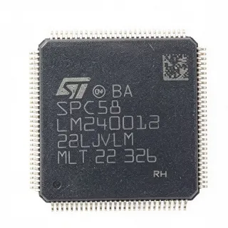
ST10F276Z5T3 - 16-Bit 40MHz MCU 832KB Flash LQFP-144 | STMicroelectronics
MPN: ST10F276Z5T3 ✗ Cuối đờiST10F276Z5T3 Tóm tắt
A microcontroller (MCU) is an integrated circuit that combines a CPU core, program and data memory, peripherals, and I/O on a single die. The ST10 family belongs to the CISC/RISC hybrid 16-bit MCU segment, sitting hierarchically above 8-bit MCUs (8051) and below 32-bit ARM Cortex-M MCUs in embedded processing taxonomy. ST10F276Z5T3 includes a CAN on-chip programmable CAN 2.0B interface, making it part of the broader embedded microcontrollers -> microcontrollers -> embedded processors and controllers -> integrated circuits hierarchy of electronic components. Its CISC/RISC architecture balances deterministic interrupt latency with DSP-class arithmetic throughput.
Key differentiating features include the hardware MAC unit enabling single-cycle 16-bit multiplication, the 832 KByte Flash for application storage, and an integrated CAN 2.0B controller. The 144-pin LQFP package provides generous I/O count suitable for automotive body, chassis, and industrial control applications. The device supports single 5 V supply operation, with on-chip voltage regulation supporting both 5 V and 3.3 V I/O. Programming is supported via the bootstrap loader and standard JTAG/OCDS debug.
Typical applications include automotive body controllers, industrial automation PLCs, motor control, HVAC systems, and CAN-connected sensor hubs where deterministic real-time response is required. The MAC unit accelerates field-oriented control (FOC) loops in motor drives, while the large Flash/RAM ratio supports protocol stacks such as J1939 or CANopen at the application layer.
When designing with the ST10F276Z5T3, ensure proper decoupling on the 5 V rail with bulk plus 100 nF ceramic capacitors adjacent to each supply pair, and follow STMicroelectronics AN2409 PCB layout guidelines for EMC compliance on automotive platforms. Note that ST officially marks the device as NRND - prefer the ST10F276Z5T6 or STM32F3 series for new designs.
This page synthesizes distributor pricing, same-family drop-in alternatives, and practical design notes not found in the manufacturer datasheet.
Bộ thay thế dễ dàng lắp đặt cho ST10F276Z5T3 — cùng gói, chân-to-chân tương thích. Các bộ phận yêu cầu hàn PCB bị loại trừ.
Các biến thể trong loạt này
Các mẫu cùng loạt có thể lắp đặt dễ dàng tương thích với ST10F276Z5T3 (cùng hình factor và footprint) — khác nhau ở Package, RAM, RoHS Status, CAN Interface, Core.
ST10F276Z5T6
✅ Drop-In📋 Tham chiếu thay thế (không có trong danh mục)
ST10F272Z2T3
✅ Drop-In📋 Tham chiếu thay thế (không có trong danh mục)
ST10F276Z5Q3
✅ Drop-InLiên hệ để biết giá
Xem tài liệu →ST10F273M-4T3
✅ Drop-In📋 Tham chiếu thay thế (không có trong danh mục)
SAF-XC886CM-8FFI5VAC
✅ Drop-InLiên hệ để biết giá
Xem tài liệu →ST10F276Z5T3 Tỷ lệ tối đa & tính chất điện
| CPU Core | ST10 (16-bit CISC/RISC with DSP functions) |
| Maximum CPU Clock | 40 MHz |
| Instruction Cycle Time | 50 ns (at 40 MHz max) |
| Program Memory (Flash) | 832 KB (832K x 8) |
| RAM | Up to 68 KB |
| MAC Unit | 16-bit x 16-bit multiplier, 40-bit accumulator |
| CAN Interface | On-chip CAN 2.0B (1 channel) |
| Operating Voltage | 5 V (with on-chip 3.3 V regulator) |
| Hộp | LQFP-144 |
| Số chân | 144 |
| Kiểu lắp đặt | Surface Mount |
| Debug Interface | JTAG / OCDS |
Cấu hình chân ST10F276Z5T3
| Chân 1 | P5.0 — Port 5 bit 0 (digital I/O) |
| Chân 2 | P5.1 — Port 5 bit 1 (digital I/O) |
| Chân 3 | P5.2 — Port 5 bit 2 (digital I/O) |
| Chân 4 | P5.3 — Port 5 bit 3 (digital I/O) |
| Chân 5 | P5.4 — Port 5 bit 4 (digital I/O) |
| Chân 6 | P5.5 — Port 5 bit 5 (digital I/O) |
| Chân 7 | P5.6 — Port 5 bit 6 (digital I/O) |
| Chân 8 | P5.7 — Port 5 bit 7 (digital I/O) |
| Chân 9 | VDD — 5 V core supply |
| Chân 10 | VSS — Ground |
| Chân 11 | P6.0 — Port 6 bit 0 / segment control |
| Chân 12 | P6.1 — Port 6 bit 1 |
| Chân 13 | P6.2 — Port 6 bit 2 |
| Chân 14 | P6.3 — Port 6 bit 3 |
| Chân 15 | P6.4 — Port 6 bit 4 |
| Chân 16 | P6.5 — Port 6 bit 5 |
| Chân 17 | P6.6 — Port 6 bit 6 |
| Chân 18 | P6.7 — Port 6 bit 7 |
| Chân 19 | P7.0 — Port 7 bit 0 (digital I/O) |
| Chân 20 | P7.1 — Port 7 bit 1 |
| Chân 21 | P7.2 — Port 7 bit 2 |
| Chân 22 | P7.3 — Port 7 bit 3 |
| Chân 23 | P7.4 — Port 7 bit 4 |
| Chân 24 | P7.5 — Port 7 bit 5 |
| Chân 25 | P7.6 — Port 7 bit 6 |
| Chân 26 | P7.7 — Port 7 bit 7 |
| Chân 27 | VDD — 5 V I/O supply |
| Chân 28 | VSS — Ground |
| Chân 29 | P8.0 — Port 8 bit 0 (CAN / digital I/O) |
| Chân 30 | P8.1 — Port 8 bit 1 (CAN / digital I/O) |
| Chân 31 | P8.2 — Port 8 bit 2 |
| Chân 32 | P8.3 — Port 8 bit 3 |
| Chân 33 | P8.4 — Port 8 bit 4 |
| Chân 34 | P8.5 — Port 8 bit 5 |
| Chân 35 | P8.6 — Port 8 bit 6 |
| Chân 36 | P8.7 — Port 8 bit 7 |
| Chân 37 | P9.0 — Port 9 bit 0 (digital I/O) |
| Chân 38 | P9.1 — Port 9 bit 1 |
| Chân 39 | P9.2 — Port 9 bit 2 |
| Chân 40 | P9.3 — Port 9 bit 3 |
| Chân 41 | P9.4 — Port 9 bit 4 |
| Chân 42 | P9.5 — Port 9 bit 5 |
| Chân 43 | P9.6 — Port 9 bit 6 |
| Chân 44 | P9.7 — Port 9 bit 7 |
| Chân 45 | VDD — 5 V supply |
| Chân 46 | VSS — Ground |
| Chân 47 | P0.0 — Port 0 bit 0 (address/data) |
| Chân 48 | P0.1 — Port 0 bit 1 (address/data) |
| Chân 49 | P0.2 — Port 0 bit 2 (address/data) |
| Chân 50 | P0.3 — Port 0 bit 3 (address/data) |
| Chân 51 | P0.4 — Port 0 bit 4 (address/data) |
| Chân 52 | P0.5 — Port 0 bit 5 (address/data) |
| Chân 53 | P0.6 — Port 0 bit 6 (address/data) |
| Chân 54 | P0.7 — Port 0 bit 7 (address/data) |
| Chân 55 | P1.0 — Port 1 bit 0 (address) |
| Chân 56 | P1.1 — Port 1 bit 1 (address) |
| Chân 57 | P1.2 — Port 1 bit 2 (address) |
| Chân 58 | P1.3 — Port 1 bit 3 (address) |
| Chân 59 | P1.4 — Port 1 bit 4 (address) |
| Chân 60 | P1.5 — Port 1 bit 5 (address) |
| Chân 61 | P1.6 — Port 1 bit 6 (address) |
| Chân 62 | P1.7 — Port 1 bit 7 (address) |
| Chân 63 | VDD — 5 V supply |
| Chân 64 | VSS — Ground |
| Chân 65 | P2.0 — Port 2 bit 0 (address) |
| Chân 66 | P2.1 — Port 2 bit 1 (address) |
| Chân 67 | P2.2 — Port 2 bit 2 (address) |
| Chân 68 | P2.3 — Port 2 bit 3 (address) |
| Chân 69 | P2.4 — Port 2 bit 4 (address) |
| Chân 70 | P2.5 — Port 2 bit 5 (address) |
| Chân 71 | P2.6 — Port 2 bit 6 (address) |
| Chân 72 | P2.7 — Port 2 bit 7 (address) |
| Chân 73 | P3.0 — Port 3 bit 0 (digital I/O) |
| Chân 74 | P3.1 — Port 3 bit 1 |
| Chân 75 | P3.2 — Port 3 bit 2 |
| Chân 76 | P3.3 — Port 3 bit 3 |
| Chân 77 | P3.4 — Port 3 bit 4 |
| Chân 78 | P3.5 — Port 3 bit 5 |
| Chân 79 | P3.6 — Port 3 bit 6 |
| Chân 80 | P3.7 — Port 3 bit 7 |
| Chân 81 | VDD — 5 V supply |
| Chân 82 | VSS — Ground |
| Chân 83 | P4.0 — Port 4 bit 0 (digital I/O) |
| Chân 84 | P4.1 — Port 4 bit 1 |
| Chân 85 | P4.2 — Port 4 bit 2 |
| Chân 86 | P4.3 — Port 4 bit 3 |
| Chân 87 | P4.4 — Port 4 bit 4 |
| Chân 88 | P4.5 — Port 4 bit 5 |
| Chân 89 | P4.6 — Port 4 bit 6 |
| Chân 90 | P4.7 — Port 4 bit 7 |
| Chân 91 | XTAL1 — Oscillator input |
| Chân 92 | XTAL2 — Oscillator output |
| Chân 93 | RSTIN — Reset input (active low) |
| Chân 94 | RSTOUT — Reset output |
| Chân 95 | NMI — Non-maskable interrupt |
| Chân 96 | VDD — 5 V supply |
| Chân 97 | VSS — Ground |
| Chân 98 | CAN_TXD — CAN transmit data |
| Chân 99 | CAN_RXD — CAN receive data |
| Chân 100 | TDI — JTAG test data in |
| Chân 101 | TDO — JTAG test data out |
| Chân 102 | TMS — JTAG test mode select |
| Chân 103 | TCK — JTAG test clock |
| Chân 104 | TRST — JTAG test reset |
| Chân 105 | BRKOUT — Breakout / OCDS signal |
| Chân 106 | BRKIN — Breakin / OCDS signal |
| Chân 107 | ALE — Address latch enable |
| Chân 108 | RD — External read strobe |
| Chân 109 | WR — External write strobe |
| Chân 110 | READY — External ready input |
| Chân 111 | VDD — 5 V supply |
| Chân 112 | VSS — Ground |
| Chân 113 | P5IN.0 — Port 5 alternate function |
| Chân 114 | P5IN.1 — Port 5 alternate function |
| Chân 115 | P5IN.2 — Port 5 alternate function |
| Chân 116 | P5IN.3 — Port 5 alternate function |
| Chân 117 | P5IN.4 — Port 5 alternate function |
| Chân 118 | P5IN.5 — Port 5 alternate function |
| Chân 119 | P5IN.6 — Port 5 alternate function |
| Chân 120 | P5IN.7 — Port 5 alternate function |
| Chân 121 | VDD — 5 V supply |
| Chân 122 | VSS — Ground |
| Chân 123 | AIN0 — Analog input channel 0 |
| Chân 124 | AIN1 — Analog input channel 1 |
| Chân 125 | AIN2 — Analog input channel 2 |
| Chân 126 | AIN3 — Analog input channel 3 |
| Chân 127 | AIN4 — Analog input channel 4 |
| Chân 128 | AIN5 — Analog input channel 5 |
| Chân 129 | AIN6 — Analog input channel 6 |
| Chân 130 | AIN7 — Analog input channel 7 |
| Chân 131 | AREF — ADC reference voltage |
| Chân 132 | AVSS — Analog ground |
| Chân 133 | AVDD — Analog 5 V supply |
| Chân 134 | VDD — 5 V supply |
| Chân 135 | VSS — Ground |
| Chân 136 | NC — Not connected (per datasheet) |
| Chân 137 | NC — Not connected (per datasheet) |
| Chân 138 | NC — Not connected (per datasheet) |
| Chân 139 | NC — Not connected (per datasheet) |
| Chân 140 | NC — Not connected (per datasheet) |
| Chân 141 | NC — Not connected (per datasheet) |
| Chân 142 | NC — Not connected (per datasheet) |
| Chân 143 | NC — Not connected (per datasheet) |
| Chân 144 | NC — Not connected (per datasheet) |
Ứng dụng tiêu biểu
ST10F276Z5T3 phù hợp cho 6 Áp dụngs: Automotive Body Control Modules, Industrial Motor Control (FOC), HVAC Climate Control Systems, CAN-Connected Sensor Hubs, Industrial PLC Controllers, Automotive Instrument Clusters.
Automotive Body Control Modules
The ST10F276Z5T3 fits automotive body controllers because its on-chip CAN 2.0B controller, 832 KB Flash, and 16-bit CPU with deterministic interrupt response support multi-node CAN networks like body electronics gateways. With 50 ns instruction cycle time, the device handles real-time lighting, window, and door control loops with sub-millisecond latency. The 5 V supply rating allows direct connection to the 12 V automotive battery via a 5 V regulator, simplifying the power tree. The 832 KB Flash accommodates full CANopen or J1939 stacks plus application firmware, while 68 KB RAM supports runtime buffers. Pin compatibility within the ST10 family preserves PCB layout for migration to the Z5T6 successor.
Được đề xuất
Industrial Motor Control (FOC)
The ST10F276Z5T3 suits field-oriented control of AC induction and PMSM motors thanks to its 16-bit hardware MAC unit and 40-bit accumulator, which accelerate Park/Clarke transforms and PI controllers in real time. The 40 MHz CPU clock and 50 ns cycle time support PWM frequencies up to 20 kHz with sufficient headroom for the FOC computational loop. Its 5 V I/O interfaces directly to standard gate drivers and op-amps used in three-phase inverters. The 144-pin LQFP provides the GPIO and timer count needed for multi-axis control. Designers should leverage the MAC unit for single-cycle 16-bit multiplies to maximize loop bandwidth.
Được đề xuất
HVAC Climate Control Systems
The ST10F276Z5T3 is well-matched to HVAC controllers because its 832 KB Flash stores multi-zone climate logic and sensor-fusion algorithms, while the 68 KB RAM supports PID parameter tables for multiple control loops. The on-chip CAN 2.0B integrates seamlessly with automotive or industrial HVAC networks for setpoint and diagnostic messaging. The 5 V analog peripherals simplify interfacing to NTC temperature sensors, pressure transducers, and valve actuators. Deterministic interrupt response from the ST10 core ensures reliable handling of safety-critical over-temperature and pressure-limit events. Designers benefit from the wide Flash headroom for future feature additions.
Được đề xuất
CAN-Connected Sensor Hubs
The ST10F276Z5T3 anchors industrial sensor hubs that aggregate multiple sensor inputs and publish them over CAN, thanks to its on-chip CAN 2.0B controller and the 832 KB Flash that fits CANopen or DeviceNet dictionaries plus application code. The 16-bit CPU performs moving-window averaging, min/max tracking, and threshold detection across many sensor channels at low latency. The 5 V GPIO drives both 3.3 V and 5 V sensors with on-chip voltage regulation. The LQFP-144 footprint accommodates the ADC and timer count needed for multi-channel synchronous sampling.
Được đề xuất
Industrial PLC Controllers
The ST10F276Z5T3 provides the deterministic execution and CAN connectivity required for compact industrial PLCs and remote I/O nodes. Its 16-bit CPU with single-cycle context switching supports fast scan times under 1 ms even with extensive ladder-logic translation. The 832 KB Flash hosts IEC 61131-3 runtimes plus user programs, while the 68 KB RAM accommodates scan buffers and stack space. The 5 V supply operates directly from 24 V industrial rails via a single regulator. Pin compatibility within the ST10F276 family enables long-term supply continuity through the Z5T6 successor.
Được đề xuất
Automotive Instrument Clusters
The ST10F276Z5T3 supports automotive instrument cluster MCUs where its 832 KB program memory and CAN 2.0B interface enable gauge control, warning indicators, and CAN-based data exchange with the vehicle bus. The 50 ns instruction cycle time drives segmented or dot-matrix LCDs at acceptable refresh rates without external display controllers. The 16-bit DSP-enhanced core handles filter algorithms on analog speed/RPM inputs from the CAN gateway. The 144-pin LQFP provides GPIO for backlight drivers, button inputs, and tell-tale LEDs. For new designs, recommend the ST10F276Z5T6 successor with longer-term availability.
Được đề xuất
Tóm tắt các sản phẩm được đề xuất
Dữ liệu tham khảo kỹ thuật cho ST10F276Z5T3 — so sánh, hướng dẫn thiết kế và thông tin tuân thủ.
Hướng dẫn chọn lựa
So sánh với các sản phẩm thay thế
| Tham số | Sản phẩm này | ST10F276Z5T6 | ST10F272Z2T3 | ST10F276Z5Q3 | ST10F273M-4T3 | SAF-XC886CM-8FFI5VAC |
|---|---|---|---|---|---|---|
| Package | LQFP-144 | LQFP-144 - same | LQFP-144 - same | LQFP-144 - same | LQFP-144 - same | TQFP-48 - different |
| Brand | STMicroelectronics | STMicroelectronics | STMicroelectronics | STMicroelectronics | STMicroelectronics | Infineon Technologies |
| CPU Core | ST10 16-bit CISC/RISC | ST10 16-bit CISC/RISC | ST10 16-bit CISC/RISC | ST10 16-bit CISC/RISC | ST10 16-bit CISC/RISC | XC800 8/16-bit CISC |
| Maximum CPU Clock | 40 MHz | 40 MHz | 40 MHz | 40 MHz | 40 MHz | 24 MHz |
| Flash Memory | 832 KB | 832 KB | 512 KB | 832 KB | 832 KB | 32 KB |
| RAM | Up to 68 KB | Up to 68 KB | Up to 40 KB | Up to 68 KB | Up to 68 KB | 2 KB |
| CAN Interface | CAN 2.0B (1 channel) | CAN 2.0B (1 channel) | CAN 2.0B (1 channel) | CAN 2.0B (1 channel) | CAN 2.0B (1 channel) | CAN (1 channel) |
| Operating Voltage | 5 V (with on-chip 3.3 V regulator) | 5 V (with on-chip 3.3 V regulator) | 5 V (with on-chip 3.3 V regulator) | 5 V (with on-chip 3.3 V regulator) | 3.3 V | 5 V |
| Lifecycle Status | NRND | Active (recommended replacement) | NRND | NRND | NRND | Mature |
Bảo phân biệt quan trọng
- Largest on-chip Flash in ST10 family (vsST10F272Z2T3)
- 5 V native I/O for automotive battery-direct design (vsST10F273M-4T3)
- Hardware 16-bit MAC unit for DSP-class math (vsSAF-XC886CM-8FFI5VAC)
Ghi chú thiết kế
The ST10F276Z5T3 requires a clean 5 V supply with bulk capacitance of at least 10 uF low-ESR tantalum or ceramic plus 100 nF ceramic placed within 5 mm of each VDD pin pair. Estimated: assuming typical switching currents of 100 mA in digital I/O, expect <50 mV supply ripple. Use a ferrite bead on the 5 V rail feeding the analog AVDD pin to prevent digital switching noise coupling into ADC conversions.
The LQFP-144 package has theta_JA around 50 C/W typical on a 4-layer JEDEC test board. Estimated: at 40 MHz full operation with all peripherals active, the device may dissipate up to 1.0 W. Derate at ambient temperatures above 85 C by ensuring adequate PCB copper area (at least 2 square inches of ground pour) or consider forced-air cooling for industrial -40 to +125 C environments.
Per the STMicroelectronics datasheet, the RSTIN pin must be held low for at least 1024 oscillator cycles during power-up to ensure proper initialization. Bootstrap loader mode is entered by pulling specific pins (P0L.4, P0L.5) high during reset. Do not leave unused ADC inputs floating - tie them to ground to prevent ADC channel crosstalk. Always issue a software reset before jumping to user code after programming to clear residual peripheral state.
Follow STMicroelectronics application note AN2409 PCB layout recommendations for EMC compliance on automotive platforms. Place the 5 V decoupling capacitors as close as possible to each VDD/VSS pin pair with short, wide traces. Use a single ground plane split only between analog AVSS and digital VSS at one point under the device. Route the CAN differential pair (CAN_TXD, CAN_RXD) as a 100-ohm impedance matched pair with no stubs. The crystal oscillator traces should be kept short and surrounded by ground pour.
Thông tin tuân thủ
Compliance status not explicitly stated in the verified web data. Refer to the STMicroelectronics product page or contact ST directly for current RoHS, REACH, and lead-free declarations. The standard variant is not AEC-Q100 qualified; check the ST10F276 automotive-grade variant for AEC-Q100 status.