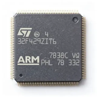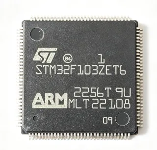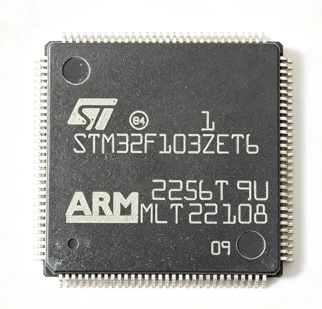
STM32F103ZET6 - 72MHz Cortex-M3 MCU 512KB Flash | STMicroelectronics
MPN: STM32F103ZET6 ✓ Hoạt độngSTM32F103ZET6 Tóm tắt
A microcontroller (MCU) is a compact integrated circuit that combines a processor core, memory, and programmable peripherals on a single chip to govern a specific operation in an embedded system. MCUs sit at the heart of the embedded electronics hierarchy - from the ARM Cortex-M processor core, through the STM32 family of 32-bit microcontrollers, up to complete embedded control systems used in industrial automation, consumer devices, and IoT products.
Key features include three 12-bit ADCs with up to 21 channels, two 12-bit DACs, a 12-channel DMA controller, and an unusually rich communication set: up to 5 USARTs, 3 SPIs, 2 I2Cs, 1 CAN 2.0B, 1 USB 2.0 Full-Speed, and 1 SDIO interface. The Cortex-M3 core delivers 1.25 DMIPS/MHz (Dhrystone 2.1), giving roughly 90 DMIPS at 72 MHz, while the Nested Vectored Interrupt Controller (NVIC) provides low-latency deterministic interrupt handling.
Architecturally, the device integrates advanced-control, general-purpose, and basic timers (including PWM timers for motor control), a real-time clock (RTC), and a CRC calculation unit. Both JTAG and Serial Wire Debug (SWD) interfaces are supported, and boot can be selected from Flash, system memory, or SRAM. The 512 KB Flash and 112 GPIOs of the LQFP144 make it the largest-pin, largest-memory STM32F103 variant, ideal for complex firmware with real-time control and multiple communication stacks.
Typical applications include industrial control and PLC systems, motor drives, medical devices, communication boards, and IoT gateways. The wide 2.0 V to 3.6 V supply range and -40C to +85C operating temperature support both battery-powered and industrial designs.
When designing with this device, decouple every VDD pin with 100 nF ceramic capacitors placed close to the pins plus one bulk capacitor, and filter VDDA with a ferrite bead to protect the 12-bit ADC noise floor. The BOOT0/BOOT1 pins must be strapped correctly at reset to select the desired boot source.
This page adds value beyond the ST datasheet by synthesizing drop-in alternatives (GD32F103ZET6, APM32E103ZET6), pricing tiers, engineering design notes, and application guidance in one citable reference.
Bộ thay thế dễ dàng lắp đặt cho STM32F103ZET6 — cùng gói, chân-to-chân tương thích. Các bộ phận yêu cầu hàn PCB bị loại trừ.
Các biến thể trong loạt này
Các mẫu cùng loạt có thể lắp đặt dễ dàng tương thích với STM32F103ZET6 (cùng hình factor và footprint) — khác nhau ở Package, Communication Interfaces, Flash Memory, Timers, Product Type.
STM32F103ZGT6
✅ Drop-InLiên hệ để biết giá
Xem tài liệu →STM32F103ZCT6
✅ Drop-InLiên hệ để biết giá
Xem tài liệu →STM32F103Z8T6
✅ Drop-InLiên hệ để biết giá
Xem tài liệu →GD32F103ZET6
✅ Drop-In📋 Tham chiếu thay thế (không có trong danh mục)
APM32E103ZET6
✅ Drop-In📋 Tham chiếu thay thế (không có trong danh mục)
STM32F103ZET6 Tỷ lệ tối đa & tính chất điện
| Core Processor | ARM Cortex-M3 32-bit RISC |
| Tần số xung maksimum | 72 MHz |
| Core Performance | 1.25 DMIPS/MHz (Dhrystone 2.1) |
| Program Memory Size | 512 KB Flash |
| SRAM Size | 64 KB |
| Supply Voltage Range | 2.0 V to 3.6 V |
| Number of GPIOs | 112 |
| ADC Resolution | 12-bit, 3 ADCs, up to 21 channels |
| DAC Resolution | 12-bit, 2 channels |
| DMA Channels | 12 |
| Communication Interfaces | 5 USART, 3 SPI, 2 I2C, 1 CAN 2.0B, 1 USB 2.0 FS, 1 SDIO |
| Timers | Advanced-control, general-purpose and basic timers plus RTC |
| Hộp | LQFP-144 (20 x 20 mm) |
| Nhiệt độ hoạt động | -40C to +85C |
| Debug Interface | JTAG and Serial Wire Debug (SWD) |
| Boot Sources | Flash, system memory, or SRAM |
| Kiểu lắp đặt | Surface Mount |
| Trạng thái RoHS | Compliant |
Cấu hình chân STM32F103ZET6
| Chân 1 | PE2 — GPIO port E bit 2 |
| Chân 2 | PE3 — GPIO port E bit 3 |
| Chân 3 | PE4 — GPIO port E bit 4 |
| Chân 4 | PE5 — GPIO port E bit 5 |
| Chân 5 | PE6 — GPIO port E bit 6 |
| Chân 6 | VBAT — Backup battery supply for RTC and backup registers |
| Chân 7 | PC13 — GPIO port C bit 13 / tamper / RTC |
| Chân 8 | PC14 — GPIO port C bit 14 / OSC32_IN |
| Chân 9 | PC15 — GPIO port C bit 15 / OSC32_OUT |
| Chân 10 | PD0 — GPIO port D bit 0 / OSC_IN |
| Chân 11 | PD1 — GPIO port D bit 1 / OSC_OUT |
| Chân 12 | PD2 — GPIO port D bit 2 / SDIO_CMD |
| Chân 13 | PD3 — GPIO port D bit 3 / USART2_CTS |
| Chân 14 | PD4 — GPIO port D bit 4 / USART2_RTS |
| Chân 15 | PD5 — GPIO port D bit 5 / USART2_TX |
| Chân 16 | PD6 — GPIO port D bit 6 / USART2_RX |
| Chân 17 | PD7 — GPIO port D bit 7 / USART2_CK |
| Chân 18 | PD8 — GPIO port D bit 8 / USART3_TX |
| Chân 19 | PD9 — GPIO port D bit 9 / USART3_RX |
| Chân 20 | PD10 — GPIO port D bit 10 / USART3_CK |
| Chân 21 | PD11 — GPIO port D bit 11 / USART3_CTS |
| Chân 22 | PD12 — GPIO port D bit 12 / USART3_RTS |
| Chân 23 | PD13 — GPIO port D bit 13 |
| Chân 24 | PD14 — GPIO port D bit 14 |
| Chân 25 | PD15 — GPIO port D bit 15 |
| Chân 26 | PG0 — GPIO port G bit 0 |
| Chân 27 | PG1 — GPIO port G bit 1 |
| Chân 28 | PG2 — GPIO port G bit 2 |
| Chân 29 | PG3 — GPIO port G bit 3 |
| Chân 30 | PG4 — GPIO port G bit 4 |
| Chân 31 | PG5 — GPIO port G bit 5 |
| Chân 32 | PG6 — GPIO port G bit 6 |
| Chân 33 | PG7 — GPIO port G bit 7 |
| Chân 34 | PG8 — GPIO port G bit 8 |
| Chân 35 | PG9 — GPIO port G bit 9 |
| Chân 36 | PG10 — GPIO port G bit 10 |
| Chân 37 | PG11 — GPIO port G bit 11 |
| Chân 38 | PG12 — GPIO port G bit 12 |
| Chân 39 | PG13 — GPIO port G bit 13 |
| Chân 40 | PG14 — GPIO port G bit 14 |
| Chân 41 | PG15 — GPIO port G bit 15 |
| Chân 42 | PB0 — GPIO port B bit 0 / ADC12_IN8 |
| Chân 43 | PB1 — GPIO port B bit 1 / ADC12_IN9 |
| Chân 44 | PB2 — GPIO port B bit 2 / BOOT1 |
| Chân 45 | PB3 — GPIO port B bit 3 / JTDO |
| Chân 46 | PB4 — GPIO port B bit 4 / NJTRST |
| Chân 47 | PB5 — GPIO port B bit 5 |
| Chân 48 | PB6 — GPIO port B bit 6 / I2C1_SCL |
| Chân 49 | PB7 — GPIO port B bit 7 / I2C1_SDA |
| Chân 50 | PB8 — GPIO port B bit 8 / CAN_RX |
| Chân 51 | PB9 — GPIO port B bit 9 / CAN_TX |
| Chân 52 | PB10 — GPIO port B bit 10 / I2C2_SCL |
| Chân 53 | PB11 — GPIO port B bit 11 / I2C2_SDA |
| Chân 54 | PB12 — GPIO port B bit 12 / SPI2_NSS |
| Chân 55 | PB13 — GPIO port B bit 13 / SPI2_SCK |
| Chân 56 | PB14 — GPIO port B bit 14 / SPI2_MISO |
| Chân 57 | PB15 — GPIO port B bit 15 / SPI2_MOSI |
| Chân 58 | PD8 — GPIO port D bit 8 / USART3_TX |
| Chân 59 | PD9 — GPIO port D bit 9 / USART3_RX |
| Chân 60 | PD10 — GPIO port D bit 10 / USART3_CK |
| Chân 61 | PD11 — GPIO port D bit 11 / USART3_CTS |
| Chân 62 | PD12 — GPIO port D bit 12 / USART3_RTS |
| Chân 63 | PD13 — GPIO port D bit 13 |
| Chân 64 | PD14 — GPIO port D bit 14 |
| Chân 65 | PD15 — GPIO port D bit 15 |
| Chân 66 | PC0 — GPIO port C bit 0 / ADC12_IN10 |
| Chân 67 | PC1 — GPIO port C bit 1 / ADC12_IN11 |
| Chân 68 | PC2 — GPIO port C bit 2 / ADC12_IN12 |
| Chân 69 | PC3 — GPIO port C bit 3 / ADC12_IN13 |
| Chân 70 | PC4 — GPIO port C bit 4 / ADC12_IN14 |
| Chân 71 | PC5 — GPIO port C bit 5 / ADC12_IN15 |
| Chân 72 | VSS_1 — Ground |
| Chân 73 | VDD_1 — Digital power supply 2.0 V to 3.6 V |
| Chân 74 | PC6 — GPIO port C bit 6 / TIM3_CH1 |
| Chân 75 | PC7 — GPIO port C bit 7 / TIM3_CH2 |
| Chân 76 | PC8 — GPIO port C bit 8 / TIM3_CH3 |
| Chân 77 | PC9 — GPIO port C bit 9 / TIM3_CH4 |
| Chân 78 | PC10 — GPIO port C bit 10 / USART3_TX |
| Chân 79 | PC11 — GPIO port C bit 11 / USART3_RX |
| Chân 80 | PC12 — GPIO port C bit 12 / USART3_CK |
| Chân 81 | PD0 — GPIO port D bit 0 / OSC_IN |
| Chân 82 | PD1 — GPIO port D bit 1 / OSC_OUT |
| Chân 83 | PD2 — GPIO port D bit 2 / SDIO_CMD |
| Chân 84 | PD3 — GPIO port D bit 3 / USART2_CTS |
| Chân 85 | PD4 — GPIO port D bit 4 / USART2_RTS |
| Chân 86 | PD5 — GPIO port D bit 5 / USART2_TX |
| Chân 87 | PD6 — GPIO port D bit 6 / USART2_RX |
| Chân 88 | PD7 — GPIO port D bit 7 / USART2_CK |
| Chân 89 | PG9 — GPIO port G bit 9 |
| Chân 90 | PG10 — GPIO port G bit 10 |
| Chân 91 | PG11 — GPIO port G bit 11 |
| Chân 92 | PG12 — GPIO port G bit 12 |
| Chân 93 | PG13 — GPIO port G bit 13 |
| Chân 94 | PG14 — GPIO port G bit 14 |
| Chân 95 | PG15 — GPIO port G bit 15 |
| Chân 96 | PB3 — GPIO port B bit 3 / JTDO |
| Chân 97 | PB4 — GPIO port B bit 4 / NJTRST |
| Chân 98 | PB5 — GPIO port B bit 5 |
| Chân 99 | PB6 — GPIO port B bit 6 / I2C1_SCL |
| Chân 100 | PB7 — GPIO port B bit 7 / I2C1_SDA |
| Chân 101 | BOOT0 — Boot mode selection input |
| Chân 102 | PB8 — GPIO port B bit 8 / CAN_RX |
| Chân 103 | PB9 — GPIO port B bit 9 / CAN_TX |
| Chân 104 | PE0 — GPIO port E bit 0 |
| Chân 105 | PE1 — GPIO port E bit 1 |
| Chân 106 | VSS_2 — Ground |
| Chân 107 | VDD_2 — Digital power supply 2.0 V to 3.6 V |
| Chân 108 | PE2 — GPIO port E bit 2 |
| Chân 109 | PE3 — GPIO port E bit 3 |
| Chân 110 | PE4 — GPIO port E bit 4 |
| Chân 111 | PE5 — GPIO port E bit 5 |
| Chân 112 | PE6 — GPIO port E bit 6 |
| Chân 113 | VSS_3 — Ground |
| Chân 114 | VDD_3 — Digital power supply 2.0 V to 3.6 V |
| Chân 115 | PA0 — GPIO port A bit 0 / WKUP / ADC12_IN0 |
| Chân 116 | PA1 — GPIO port A bit 1 / ADC12_IN1 |
| Chân 117 | PA2 — GPIO port A bit 2 / USART2_TX / ADC12_IN2 |
| Chân 118 | PA3 — GPIO port A bit 3 / USART2_RX / ADC12_IN3 |
| Chân 119 | VSS_4 — Ground |
| Chân 120 | VDD_4 — Digital power supply 2.0 V to 3.6 V |
| Chân 121 | PA4 — GPIO port A bit 4 / SPI1_NSS / ADC12_IN4 / DAC_OUT1 |
| Chân 122 | PA5 — GPIO port A bit 5 / SPI1_SCK / ADC12_IN5 / DAC_OUT2 |
| Chân 123 | PA6 — GPIO port A bit 6 / SPI1_MISO / ADC12_IN6 |
| Chân 124 | PA7 — GPIO port A bit 7 / SPI1_MOSI / ADC12_IN7 |
| Chân 125 | PC4 — GPIO port C bit 4 / ADC12_IN14 |
| Chân 126 | PC5 — GPIO port C bit 5 / ADC12_IN15 |
| Chân 127 | PB0 — GPIO port B bit 0 / ADC12_IN8 |
| Chân 128 | PB1 — GPIO port B bit 1 / ADC12_IN9 |
| Chân 129 | PB2 — GPIO port B bit 2 / BOOT1 |
| Chân 130 | PE7 — GPIO port E bit 7 |
| Chân 131 | PE8 — GPIO port E bit 8 |
| Chân 132 | PE9 — GPIO port E bit 9 |
| Chân 133 | PE10 — GPIO port E bit 10 |
| Chân 134 | PE11 — GPIO port E bit 11 |
| Chân 135 | PE12 — GPIO port E bit 12 |
| Chân 136 | PE13 — GPIO port E bit 13 |
| Chân 137 | PE14 — GPIO port E bit 14 |
| Chân 138 | PE15 — GPIO port E bit 15 |
| Chân 139 | PB10 — GPIO port B bit 10 / I2C2_SCL |
| Chân 140 | PB11 — GPIO port B bit 11 / I2C2_SDA |
| Chân 141 | VSS_5 — Ground |
| Chân 142 | VDD_5 — Digital power supply 2.0 V to 3.6 V |
| Chân 143 | PB12 — GPIO port B bit 12 / SPI2_NSS |
| Chân 144 | PB13 — GPIO port B bit 13 / SPI2_SCK |
Ứng dụng tiêu biểu
STM32F103ZET6 phù hợp cho 6 Áp dụngs: Industrial Control and PLC Systems, Motor Drives and Motion Control, Medical Devices and Patient Monitoring, IoT Gateways and Communication Boards, Consumer Appliances and White Goods, Test and Measurement Instrumentation.
Industrial Control and PLC Systems
The STM32F103ZET6 fits industrial PLC and control systems because its 112 GPIOs, 5 USARTs, and CAN 2.0B interface allow direct connection to field I/O modules, encoders, and industrial buses without external glue logic. The 512 KB Flash accommodates ladder-logic interpreters and Modbus stacks, while the 72 MHz Cortex-M3 core executes deterministic scan cycles. In a typical PLC slice, the MCU scans digital inputs through port expanders, drives relay outputs via shift registers, and exchanges data over CAN or RS-485. The 12-bit ADCs sample 4-20 mA sensor loops, and the 12-channel DMA offloads conversion transfers to keep scan jitter low. Unlike a smaller STM32F103 variant, the LQFP-144 package exposes enough pins to avoid multiplexing conflicts between communication peripherals and I/O, simplifying PCB routing in multi-module racks.
Được đề xuất
Motor Drives and Motion Control
The STM32F103ZET6 is used in motor drives because its advanced-control timers generate complementary PWM with dead-time insertion for three-phase inverters, while three 12-bit ADCs with up to 21 channels sample phase currents and DC-link voltage simultaneously. The 12-channel DMA moves ADC results to memory without CPU intervention, preserving bandwidth for field-oriented control math at 72 MHz. In a typical BLDC or PMSM drive, the MCU runs a current loop at 10-20 kHz, a speed loop at 1 kHz, and communicates setpoints over CAN 2.0B or USART. The 512 KB Flash stores motor parameter tables and communication stacks. Compared with lower-pin STM32F103 parts, the LQFP-144 provides enough GPIOs for gate-driver fault inputs, encoder feedback, and user interface without port sharing.
Được đề xuất
Medical Devices and Patient Monitoring
The STM32F103ZET6 suits medical monitoring equipment because its three 12-bit ADCs and two 12-bit DACs support multi-channel biosignal acquisition and analog output calibration, while the 512 KB Flash holds signal-processing firmware and communication protocols. In a patient monitor, the MCU samples ECG or SpO2 front-end outputs through the ADCs, filters them in real time, and streams results over USB 2.0 Full-Speed or USART to a host display. The 112 GPIOs drive status LEDs, buttons, and alarm outputs. The 2.0 V to 3.6 V supply range allows direct operation from a regulated 3.3 V medical rail, and the -40C to +85C temperature range covers clinical environments. Designers should filter VDDA with a ferrite bead and keep analog and digital grounds separated to protect the ADC noise floor.
Được đề xuất
IoT Gateways and Communication Boards
The STM32F103ZET6 is used in IoT gateways because its communication peripheral set - 5 USARTs, 3 SPIs, 2 I2Cs, 1 CAN 2.0B, 1 USB 2.0 Full-Speed, and 1 SDIO - allows simultaneous connection to wireless modules, sensors, and storage without external bridges. In a gateway design, the MCU runs a protocol stack that translates Modbus or CAN field data into MQTT or HTTP payloads forwarded through an external Wi-Fi or cellular module over USART or SPI. The SDIO interface supports local data logging to an SD card, and the 512 KB Flash stores the TCP/IP stack and configuration. The 72 MHz core provides enough throughput for packet parsing and encryption, while the 112 GPIOs accommodate status indicators and module control lines.
Được đề xuất
Consumer Appliances and White Goods
The STM32F103ZET6 fits consumer appliance control because its 112 GPIOs and integrated timers drive multiple loads - motors, heaters, valves, and user-interface panels - from a single MCU, reducing board count. In a washing machine or refrigerator controller, the MCU reads temperature and position sensors through the 12-bit ADCs, drives triacs and relays via GPIO and PWM timers, and manages a display and touch panel over SPI or I2C. The 512 KB Flash stores cycle profiles and safety logic, and the CAN or USART interface supports factory programming and diagnostics. The 2.0 V to 3.6 V supply and -40C to +85C range cover appliance environments. Compared with smaller STM32F103 packages, the LQFP-144 avoids pin multiplexing between the display bus and motor-control timers.
Được đề xuất
Test and Measurement Instrumentation
The STM32F103ZET6 is used in benchtop and portable instruments because its three 12-bit ADCs with up to 21 channels and two 12-bit DACs support multi-point signal acquisition and analog stimulus generation, while the 12-channel DMA sustains high sample rates without CPU stalls. In a data logger or signal analyzer, the MCU samples conditioned inputs, applies digital filtering, and streams results over USB 2.0 Full-Speed to a PC, or logs them to an SD card through the SDIO interface. The 512 KB Flash holds calibration tables and measurement firmware, and the 72 MHz core handles FFT and averaging routines. The 112 GPIOs drive range relays, input multiplexers, and front-panel controls. Designers should keep the analog supply filtered and route ADC inputs away from switching nodes to preserve measurement accuracy.
Được đề xuất
Tóm tắt các sản phẩm được đề xuất
Dữ liệu tham khảo kỹ thuật cho STM32F103ZET6 — so sánh, hướng dẫn thiết kế và thông tin tuân thủ.
Hướng dẫn chọn lựa
So sánh với các sản phẩm thay thế
| Tham số | Sản phẩm này | STM32F103ZGT6 | STM32F103ZCT6 | GD32F103ZET6 | APM32E103ZET6 |
|---|---|---|---|---|---|
| Package | LQFP-144 | LQFP-144 - same | LQFP-144 - same | LQFP-144 - same | LQFP-144 - same |
| Brand | STMicroelectronics | STMicroelectronics | STMicroelectronics | GigaDevice | Geehy |
| Core | ARM Cortex-M3 | ARM Cortex-M3 | ARM Cortex-M3 | ARM Cortex-M3 | ARM Cortex-M3 |
| Max Clock Frequency | 72 MHz | 72 MHz | 72 MHz | 108 MHz | 120 MHz |
| Flash Memory | 512 KB | 1 MB | 256 KB | 512 KB | 512 KB |
| SRAM | 64 KB | 96 KB | 48 KB | 64 KB | 128 KB |
| GPIO Count | 112 | 112 | 112 | 112 | 112 |
| Supply Voltage | 2.0 V to 3.6 V | 2.0 V to 3.6 V | 2.0 V to 3.6 V | 2.6 V to 3.6 V | 2.0 V to 3.6 V |
| CAN Interface | 1x CAN 2.0B | 1x CAN 2.0B | 1x CAN 2.0B | 1x CAN 2.0B | 1x CAN 2.0B |
| USB Interface | 1x USB 2.0 Full-Speed | 1x USB 2.0 Full-Speed | 1x USB 2.0 Full-Speed | 1x USB 2.0 Full-Speed | 1x USB 2.0 Full-Speed |
Bảo phân biệt quan trọng
- Largest Flash and GPIO count in the STM32F103 line (vsSTM32F103ZCT6)
- Native ST toolchain and ecosystem support (vsGD32F103ZET6)
- Lower clock ceiling than pin-compatible clones (vsAPM32E103ZET6)
Ghi chú thiết kế
Decouple every VDD pin (VDD_1 through VDD_5) with a 100 nF ceramic capacitor placed as close to the pin as possible, plus at least one 4.7 uF to 10 uF bulk capacitor near the package. Filter VDDA with a ferrite bead followed by a 100 nF and 1 uF capacitor to protect the 12-bit ADC noise floor. Keep the analog supply within 2.0 V to 3.6 V and ensure VDDA never exceeds VDD by more than 300 mV during power sequencing.
Route the 8 MHz main crystal and 32.768 kHz RTC crystal with short, symmetric traces and guard them with ground. Place the load capacitors close to the crystal pins and avoid routing high-speed signals such as USB or SDIO underneath the oscillator area. For the LQFP-144, use a solid ground plane under the device and connect the exposed thermal pad area with multiple vias if the package variant includes one.
Strap BOOT0 low and BOOT1 (PB2) as required at reset to select boot from Flash; incorrect strapping causes the device to enter the system memory bootloader unexpectedly. Do not leave NRST floating - add a 100 nF capacitor to ground and a 10 kOhm pull-up. When migrating to a GD32F103ZET6 drop-in, re-validate clock configuration and Flash wait states because the clone supports up to 108 MHz with zero-wait Flash buffering.
Thông tin tuân thủ
RoHS and REACH compliance per STMicroelectronics product page. Not AEC-Q100 qualified - the STM32F103ZET6 is an industrial/consumer grade device rated -40C to +85C.