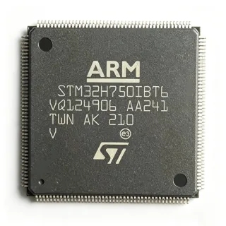
STM32H743IGT6 - 480MHz Cortex-M7 MCU 1MB Flash | STMicroelectronics
MPN: STM32H743IGT6 ✓ Hoạt độngSTM32H743IGT6 Tóm tắt
A microcontroller (MCU) is a single-chip computer that integrates a CPU core, memory, and programmable peripherals. The STM32H743 belongs to the 32-bit MCU family (ARM Cortex-M class), which sits above 8-bit/16-bit microcontrollers in the semiconductor hierarchy: transistor -> logic gate -> CPU core -> microcontroller -> embedded system. Cortex-M7 devices target high-performance embedded applications that previously required a DSP or microprocessor, and the STM32H7 line extends the STM32 family from mainstream (F0/F1/F4) into premium real-time processing tiers.
Key features of the STM32H743IGT6 include: 1 MB dual-bank Flash with ECC, 1 MB SRAM split into DTCM, AXI SRAM, SRAM1-4, and Backup SRAM; a 16-bit Chrom-ART (DMA2D) accelerator; JPEG codec in hardware; up to 35 communication interfaces including 3x SPI, 4x USART/UART, 2x UART, 3x I2C, 2x CAN, USB 2.0 FS+OTG, SDMMC, and Ethernet; a 16-bit parallel camera interface; and 3x 12-bit ADCs at 3.6 MSPS plus 2x 12-bit DACs. The internal SMPS step-down converter reduces core current consumption by approximately 30% versus an external LDO supply.
The architecture uses a 7-stage superscalar pipeline with branch prediction, single-precision and double-precision FPU, and an instruction/data cache. The AXI bus matrix (64-bit wide, 480 MHz) gives sustained memory bandwidth above 4 MB/s, suitable for TFT-LCD framebuffers and audio streaming. Advanced peripherals include a TFT-LCD controller (up to XGA resolution), cryptographic accelerators (AES, hash, RNG), and a true random number generator (TRNG).
Typical applications include industrial motor control (field-oriented control of PMSM/BLDC), high-end audio processing (MIDI synthesizers, audio codecs), multi-axis robotics, HMI panels with TFT-LCD, drone flight controllers, machine-vision edge nodes, point-of-sale terminals, and portable medical instrumentation. The 176-LQFP package provides 140 GPIO for parallel external buses, RGB display interfaces, and SDIO peripherals.
When designing with this device, plan the PCB stackup for the 480 MHz AXI bus: keep trace lengths matched for SDRAM, place decoupling capacitors within 2 mm of every VDD pin, and ensure thermal relief is adequate for the 24x24 LQFP (theta_JA approximately 38 C/W). Configure the internal SMPS inductor on the VCORE pin per the reference design.
This page synthesizes distributor pricing, drop-in pin-compatible alternatives, parametric comparisons, and PCB design notes that go beyond the ST datasheet summary - helping procurement, firmware, and hardware engineers make informed BOM decisions in a single read.
Bộ thay thế dễ dàng lắp đặt cho STM32H743IGT6 — cùng gói, chân-to-chân tương thích. Các bộ phận yêu cầu hàn PCB bị loại trừ.
Các biến thể trong loạt này
Các mẫu cùng loạt có thể lắp đặt dễ dàng tương thích với STM32H743IGT6 (cùng hình factor và footprint) — khác nhau ở Package, Communication Interfaces, FPU, Flash Memory, Maximum Clock Frequency.
STM32H753IGT6
✅ Drop-In📋 Tham chiếu thay thế (không có trong danh mục)
STM32H750IBT6
✅ Drop-InLiên hệ để biết giá
Xem tài liệu →STM32H742IGT6
✅ Drop-In ⚠️ Thông số chưa được xác minh📋 Tham chiếu thay thế (không có trong danh mục)
STM32H733VGT6
✅ Drop-In ⚠️ Thông số chưa được xác minhLiên hệ để biết giá
Xem tài liệu →STM32H735IGT6
✅ Drop-In ⚠️ Thông số chưa được xác minh📋 Tham chiếu thay thế (không có trong danh mục)
STM32H743IGT6 Tỷ lệ tối đa & tính chất điện
| Core Architecture | ARM Cortex-M7 (32-bit) |
| Maximum Clock Speed | 480 MHz |
| CoreMark Performance | 2400 CoreMark |
| DMIPS Performance | 1027 DMIPS |
| Program Memory (Flash) | 1 MB (dual-bank with ECC) |
| SRAM | 1 MB (DTCM + AXI SRAM + SRAM1-4 + Backup SRAM) |
| L1 Cache | 16 KB I-cache + 16 KB D-cache |
| FPU | Double-precision IEEE 754 |
| Điện áp cung cấp | 1.62 V to 3.6 V |
| Hộp | 176-LQFP (24x24 mm) |
| GPIO Count | 140 |
| Nhiệt độ hoạt động | -40C to +85C (Grade 6) |
| ADC | 3x 12-bit, 3.6 MSPS |
| DAC | 2x 12-bit |
| Communication Interfaces | USB FS/OTG, 2x CAN, 3x SPI, 4x USART/UART, 3x I2C, SDMMC, Ethernet |
| Kiểu lắp đặt | Surface Mount |
| Trạng thái RoHS | Compliant |
| Internal SMPS | Yes (step-down DC-DC for VCORE) |
| Cryptography | AES-256, hash (SHA-1/2), TRNG |
| Display Controller | TFT-LCD up to XGA (JPEG codec + DMA2D accelerator) |
Cấu hình chân STM32H743IGT6
| Chân 1 | PE2 — GPIO PE2 / TRACECLK / SPI4_SCK |
| Chân 2 | PE3 — GPIO PE3 / TRACED0 |
| Chân 3 | PE4 — GPIO PE4 / TRACED1 |
| Chân 4 | PE5 — GPIO PE5 / TRACED2 |
| Chân 5 | PE6 — GPIO PE6 / TRACED3 |
| Chân 6 | VBAT — Backup battery supply input |
| Chân 7 | PC13 — GPIO PC13 / RTC_OUT / WKUP1 |
| Chân 8 | PC14 — GPIO PC14 / OSC32_IN |
| Chân 9 | PC15 — GPIO PC15 / OSC32_OUT |
| Chân 10 | VSS — Digital ground |
| Chân 11 | VDD — Digital supply 1.62-3.6 V |
| Chân 12 | OSC_IN — HSE oscillator input |
| Chân 13 | OSC_OUT — HSE oscillator output |
| Chân 14 | NRST — Reset input, active low |
| Chân 15 | PC0 — GPIO PC0 / ADC1_INP10 |
| Chân 16 | PC1 — GPIO PC1 / ADC1_INP11 |
| Chân 17 | PC2 — GPIO PC2 / ADC1_INP12 |
| Chân 18 | PC3 — GPIO PC3 / ADC1_INP13 |
| Chân 19 | VSSA — Analog ground |
| Chân 20 | VDDA — Analog supply |
| Chân 21 | PA0 — GPIO PA0 / ADC1_INP0 / WKUP0 |
| Chân 22 | PA1 — GPIO PA1 / ADC1_INP1 |
| Chân 23 | PA2 — GPIO PA2 / ADC1_INP2 / USART2_TX |
| Chân 24 | PA3 — GPIO PA3 / ADC1_INP3 / USART2_RX |
| Chân 25 | VSS — Digital ground |
| Chân 26 | VDD — Digital supply |
| Chân 27 | PA4 — GPIO PA4 / ADC1_INP4 / DAC1_OUT1 |
| Chân 28 | PA5 — GPIO PA5 / ADC1_INP5 / DAC1_OUT2 |
| Chân 29 | PA6 — GPIO PA6 / ADC1_INP6 |
| Chân 30 | PA7 — GPIO PA7 / ADC1_INP7 |
| Chân 31 | PC4 — GPIO PC4 / ADC1_INP14 |
| Chân 32 | PC5 — GPIO PC5 / ADC1_INP15 |
| Chân 33 | PB0 — GPIO PB0 / ADC1_INP8 |
| Chân 34 | PB1 — GPIO PB1 / ADC1_INP9 |
| Chân 35 | PB2 — GPIO PB2 / BOOT1 |
| Chân 36 | PE7 — GPIO PE7 |
| Chân 37 | PE8 — GPIO PE8 |
| Chân 38 | PE9 — GPIO PE9 |
| Chân 39 | PE10 — GPIO PE10 |
| Chân 40 | PE11 — GPIO PE11 |
| Chân 41 | PE12 — GPIO PE12 |
| Chân 42 | PE13 — GPIO PE13 |
| Chân 43 | PE14 — GPIO PE14 |
| Chân 44 | PE15 — GPIO PE15 |
| Chân 45 | PB10 — GPIO PB10 / USART3_TX |
| Chân 46 | PB11 — GPIO PB11 / USART3_RX |
| Chân 47 | VCAP_1 — VCORE decoupling (internal SMPS output cap) |
| Chân 48 | VDD — Digital supply |
| Chân 49 | PB12 — GPIO PB12 / SPI2_NSS |
| Chân 50 | PB13 — GPIO PB13 / SPI2_SCK |
| Chân 51 | PB14 — GPIO PB14 / SPI2_MISO |
| Chân 52 | PB15 — GPIO PB15 / SPI2_MOSI |
| Chân 53 | PD8 — GPIO PD8 / USART3_TX |
| Chân 54 | PD9 — GPIO PD9 / USART3_RX |
| Chân 55 | PD10 — GPIO PD10 |
| Chân 56 | PD11 — GPIO PD11 |
| Chân 57 | PD12 — GPIO PD12 |
| Chân 58 | PD13 — GPIO PD13 |
| Chân 59 | PD14 — GPIO PD14 |
| Chân 60 | PD15 — GPIO PD15 |
| Chân 61 | PC6 — GPIO PC6 / USART6_TX |
| Chân 62 | PC7 — GPIO PC7 / USART6_RX |
| Chân 63 | PC8 — GPIO PC8 |
| Chân 64 | PC9 — GPIO PC9 |
| Chân 65 | PA8 — GPIO PA8 / TIM1_CH1 / MCO1 |
| Chân 66 | PA9 — GPIO PA9 / USART1_TX |
| Chân 67 | PA10 — GPIO PA10 / USART1_RX |
| Chân 68 | PA11 — GPIO PA11 / USB_OTG_FS_DM |
| Chân 69 | PA12 — GPIO PA12 / USB_OTG_FS_DP |
| Chân 70 | PA13 — GPIO PA13 / SWDIO |
| Chân 71 | VCAP_2 — VCORE decoupling |
| Chân 72 | VDD — Digital supply |
| Chân 73 | PA14 — GPIO PA14 / SWCLK |
| Chân 74 | PA15 — GPIO PA15 / JTDI / TIM2_CH1 |
| Chân 75 | PC10 — GPIO PC10 / UART4_TX / SDMMC2_D2 |
| Chân 76 | PC11 — GPIO PC11 / UART4_RX / SDMMC2_D3 |
| Chân 77 | PC12 — GPIO PC12 / UART5_TX / SDMMC2_CK |
| Chân 78 | PD0 — GPIO PD0 / FMC_D2 |
| Chân 79 | PD1 — GPIO PD1 / FMC_D3 |
| Chân 80 | PD2 — GPIO PD2 / SDMMC1_CMD / UART5_RX |
| Chân 81 | PD3 — GPIO PD3 / FMC_CLK |
| Chân 82 | PD4 — GPIO PD4 / FMC_NOE |
| Chân 83 | PD5 — GPIO PD5 / FMC_NWE |
| Chân 84 | VSS — Digital ground |
| Chân 85 | VDD — Digital supply |
| Chân 86 | PD6 — GPIO PD6 / FMC_NWAIT |
| Chân 87 | PD7 — GPIO PD7 / FMC_NE1 |
| Chân 88 | PG9 — GPIO PG9 / USART6_RX |
| Chân 89 | PG10 — GPIO PG10 |
| Chân 90 | PG11 — GPIO PG11 |
| Chân 91 | PG12 — GPIO PG12 |
| Chân 92 | PG13 — GPIO PG13 |
| Chân 93 | PG14 — GPIO PG14 |
| Chân 94 | VSS — Digital ground |
| Chân 95 | VDD — Digital supply |
| Chân 96 | PG15 — GPIO PG15 |
| Chân 97 | PB3 — GPIO PB3 / JTDO / TIM2_CH2 |
| Chân 98 | PB4 — GPIO PB4 / NJTRST |
| Chân 99 | PB5 — GPIO PB5 / I2C1_SMBAI |
| Chân 100 | PB6 — GPIO PB6 / I2C1_SCL |
| Chân 101 | PB7 — GPIO PB7 / I2C1_SDA |
| Chân 102 | BOOT0 — Boot mode select |
| Chân 103 | PB8 — GPIO PB8 / I2C1_SCL |
| Chân 104 | PB9 — GPIO PB9 / I2C1_SDA |
| Chân 105 | PE0 — GPIO PE0 / TIM4_ETR |
| Chân 106 | PE1 — GPIO PE1 |
| Chân 107 | VSS — Digital ground |
| Chân 108 | VDD — Digital supply |
| Chân 109 | PF0 — GPIO PF0 / FMC_A0 |
| Chân 110 | PF1 — GPIO PF1 / FMC_A1 |
| Chân 111 | PF2 — GPIO PF2 / FMC_A2 |
| Chân 112 | PF3 — GPIO PF3 / FMC_A3 |
| Chân 113 | PF4 — GPIO PF4 / FMC_A4 |
| Chân 114 | PF5 — GPIO PF5 / FMC_A5 |
| Chân 115 | VSS — Digital ground |
| Chân 116 | VDD — Digital supply |
| Chân 117 | PF6 — GPIO PF6 / TIM10_CH1 |
| Chân 118 | PF7 — GPIO PF7 / TIM11_CH1 |
| Chân 119 | PF8 — GPIO PF8 / TIM12_CH1 |
| Chân 120 | PF9 — GPIO PF9 / TIM13_CH1 |
| Chân 121 | PF10 — GPIO PF10 / TIM14_CH1 |
| Chân 122 | PF11 — GPIO PF11 |
| Chân 123 | PH0 — GPIO PH0 / OSC_IN |
| Chân 124 | PH1 — GPIO PH1 / OSC_OUT |
| Chân 125 | VSS — Digital ground |
| Chân 126 | VDD — Digital supply |
| Chân 127 | PC14 — GPIO PC14 / OSC32_IN (duplicate alt) |
| Chân 128 | PC15 — GPIO PC15 / OSC32_OUT (duplicate alt) |
| Chân 129 | VSS — Digital ground |
| Chân 130 | VDD — Digital supply |
| Chân 131 | PG0 — GPIO PG0 / FMC_A10 |
| Chân 132 | PG1 — GPIO PG1 / FMC_A11 |
| Chân 133 | PG2 — GPIO PG2 / FMC_A12 |
| Chân 134 | PG3 — GPIO PG3 / FMC_A13 |
| Chân 135 | PG4 — GPIO PG4 / FMC_A14 |
| Chân 136 | PG5 — GPIO PG5 / FMC_A15 |
| Chân 137 | PG6 — GPIO PG6 |
| Chân 138 | PG7 — GPIO PG7 |
| Chân 139 | PG8 — GPIO PG8 |
| Chân 140 | VSS — Digital ground |
| Chân 141 | VDD — Digital supply |
| Chân 142 | PF12 — GPIO PF12 / FMC_A6 |
| Chân 143 | PF13 — GPIO PF13 / FMC_A7 |
| Chân 144 | PF14 — GPIO PF14 / FMC_A8 |
| Chân 145 | PF15 — GPIO PF15 / FMC_A9 |
| Chân 146 | PG10 — GPIO PG10 (duplicate function) |
| Chân 147 | PA0 — GPIO PA0 (WKUP, alt) |
| Chân 148 | PA1 — GPIO PA1 (alt) |
| Chân 149 | PA2 — GPIO PA2 (alt) |
| Chân 150 | PA3 — GPIO PA3 (alt) |
| Chân 151 | VSS — Digital ground |
| Chân 152 | VDD — Digital supply |
| Chân 153 | PA4 — GPIO PA4 (alt) |
| Chân 154 | PA5 — GPIO PA5 (alt) |
| Chân 155 | PA6 — GPIO PA6 (alt) |
| Chân 156 | PA7 — GPIO PA7 (alt) |
| Chân 157 | PB0 — GPIO PB0 (alt) |
| Chân 158 | PB1 — GPIO PB1 (alt) |
| Chân 159 | PB2 — GPIO PB2 (alt) |
| Chân 160 | PF12 — GPIO PF12 (alt) |
| Chân 161 | VSS — Digital ground |
| Chân 162 | VDD — Digital supply |
| Chân 163 | PC6 — GPIO PC6 (alt) |
| Chân 164 | PC7 — GPIO PC7 (alt) |
| Chân 165 | PC8 — GPIO PC8 (alt) |
| Chân 166 | PC9 — GPIO PC9 (alt) |
| Chân 167 | PA8 — GPIO PA8 (alt) |
| Chân 168 | PA9 — GPIO PA9 (alt) |
| Chân 169 | PA10 — GPIO PA10 (alt) |
| Chân 170 | PA11 — GPIO PA11 (alt) |
| Chân 171 | PA12 — GPIO PA12 (alt) |
| Chân 172 | PA13 — GPIO PA13 (alt) |
| Chân 173 | VCAP_3 — VCORE decoupling |
| Chân 174 | VDD — Digital supply |
| Chân 175 | PA14 — GPIO PA14 (alt) |
| Chân 176 | PA15 — GPIO PA15 (alt) |
Ứng dụng tiêu biểu
STM32H743IGT6 phù hợp cho 7 Áp dụngs: Industrial Motor Control (FOC / PMSM), High-End TFT-LCD HMI Panels, Multi-Axis Robotics and CNC Control, Audio Processing and MIDI Synthesizers, Machine Vision and Image Processing, Drone Flight Controllers, Portable Medical Instrumentation.
Industrial Motor Control (FOC / PMSM)
The STM32H743IGT6 is engineered for high-performance motor control including field-oriented control (FOC) of PMSM and BLDC motors. The 480 MHz Cortex-M7 with double-precision FPU executes the FOC loop in well under 10 microseconds, and the 3x 12-bit ADCs at 3.6 MSPS provide simultaneous current sampling on three shunt resistors without aliasing. The high-resolution timer (HRTIM) with 184 ps resolution drives center-aligned PWM up to 100 kHz. The built-in SMPS reduces BOM cost versus an external LDO, and the cryptographic accelerators are not required for motor-control firmware, making the H743 a cost-optimized choice versus the H753.
Được đề xuất
High-End TFT-LCD HMI Panels
The STM32H743IGT6 drives TFT-LCD panels up to XGA (1024x768) using the integrated LTDC controller, Chrom-ART (DMA2D) 2D accelerator, and on-chip JPEG codec. The 1 MB of AXI SRAM holds a full XGA framebuffer at 16 bpp without external SDRAM, and the 16-bit parallel display interface supports pixel clocks up to 83 MHz for 60 fps refresh. The double-precision FPU accelerates anti-aliased font rendering, and the SDMMC controller boots firmware from a microSD card at 50 MB/s. For HMI panels in industrial equipment, the H743 is widely adopted as the cost-effective sweet spot between the Cortex-M4 STM32F4 line and the more expensive STM32MP1 microprocessor series.
Được đề xuất
Multi-Axis Robotics and CNC Control
The STM32H743IGT6's 480 MHz Cortex-M7 core is well suited to multi-axis robotics including 6-DoF robotic arms, CNC controllers, and pick-and-place machines. The DSP extensions accelerate inverse-kinematics math, the double-precision FPU handles 3D coordinate transforms, and the 16-bit parallel camera interface accepts a vision module for closed-loop position control. With 140 GPIO and 8 USART/UART ports, the H743 can drive up to 8 stepper motors via external drivers, and the 2x CAN interfaces support CANopen or CAN-FD for industrial robot bus protocols. The 1 MB Flash accommodates complex motion-planning firmware without external memory.
Được đề xuất
Audio Processing and MIDI Synthesizers
The STM32H743IGT6's 480 MHz Cortex-M7 with double-precision FPU executes high-quality audio processing including 32-voice polyphonic synthesizers, reverb, and effects at 48 kHz/24-bit. The SAI (Serial Audio Interface) supports I2S/TDM audio codecs up to 192 kHz, the 2x 12-bit DACs provide line-level analog output, and the I2C peripheral controls codec chips. The DSP extensions accelerate FFT-based spectral processing, and the 1 MB SRAM holds multi-second audio buffers without external memory. The 176-LQFP package provides ample GPIO for MIDI DIN-5 in/out and footswitch jacks.
Được đề xuất
Machine Vision and Image Processing
The STM32H743IGT6 supports machine-vision edge nodes with its 16-bit parallel camera interface, hardware JPEG codec, and Chrom-ART (DMA2D) graphics accelerator. The 1 MB of SRAM accommodates a VGA-resolution framebuffer plus edge-detection kernels, and the AXI bus matrix sustains 240 MHz memory bandwidth to keep up with OV5640-class 5 MP sensors. The Cortex-M7 DSP extensions accelerate Sobel and Canny edge-detection filters, while the USB 2.0 OTG streams processed frames to a host. For embedded vision tasks below 30 fps at QVGA, the H743 is competitive with low-end Cortex-A Linux SOMs at much lower power and BOM cost.
Được đề xuất
Drone Flight Controllers
The STM32H743IGT6 has become the de-facto flight-controller reference MCU for high-end racing and cinematic drones running PX4 or ArduPilot. The 480 MHz Cortex-M7 runs the attitude-control loop at 8 kHz, the double-precision FPU handles quaternion math, and the high-resolution timer drives DSHOT/OneShot/ProShot ESC protocols. The 3x ADCs at 3.6 MSPS sample IMU and gyroscope data with low latency, and the USB OTG provides the bootloader for firmware updates. The internal SMPS reduces weight versus an external LDO, and the 176-LQFP package has enough GPIO for GPS, magnetometer, optical-flow, and 4x ESC outputs simultaneously.
Được đề xuất
Portable Medical Instrumentation
The STM32H743IGT6 suits portable medical devices such as patient monitors, infusion pumps, and handheld ultrasound controllers. The 480 MHz Cortex-M7 processes ECG/EEG signal chains, the 3x 12-bit ADCs at 3.6 MSPS provide adequate resolution for biopotential signals, and the AES-256 hardware accelerator (not available on H743 - see H753) secures patient data at rest. The 1 MB Flash stores firmware with built-in self-test (BIST) routines, and the USB OTG connects to PC-based diagnostic software. The -40C to +85C operating temperature range supports both clinical and field-deployment scenarios.
Được đề xuất
Tóm tắt các sản phẩm được đề xuất
Dữ liệu tham khảo kỹ thuật cho STM32H743IGT6 — so sánh, hướng dẫn thiết kế và thông tin tuân thủ.
Hướng dẫn chọn lựa
So sánh với các sản phẩm thay thế
| Tham số | Sản phẩm này | STM32H753IGT6 | STM32H750IBT6 | STM32H742IGT6 | STM32H733VGT6 | STM32H735IGT6 |
|---|---|---|---|---|---|---|
| Package | 176-LQFP (24x24 mm) | 176-LQFP (24x24) - same | 176-LQFP (24x24) - same | 176-LQFP (24x24) - same | 176-LQFP (24x24) - same | 176-LQFP (24x24) - same |
| Brand | STMicroelectronics | STMicroelectronics | STMicroelectronics | STMicroelectronics | STMicroelectronics | STMicroelectronics |
| Core | Cortex-M7 @ 480 MHz | Cortex-M7 @ 480 MHz | Cortex-M7 @ 480 MHz | Cortex-M7 @ 480 MHz | Cortex-M7 @ 550 MHz | Cortex-M7 @ 550 MHz |
| Flash | 1 MB dual-bank | 2 MB dual-bank | 128 KB (boot from external) | 1 MB dual-bank | 1 MB dual-bank | 1 MB dual-bank |
| SRAM | 1 MB | 1 MB | 864 KB | 1 MB | 564 KB | 564 KB |
| Cryptography | No crypto accelerator | AES, hash, TRNG, SFI | AES, hash, TRNG | No crypto | AES, hash, TRNG | AES, hash, TRNG |
| TrustZone | No | No | No | No | Yes | Yes |
| Internal SMPS | Yes | Yes | Yes | Yes | Yes | Yes |
| Approx Unit Price (qty 1, USD) | 16.20 | 19.50 | 12.80 | 15.40 | 17.60 | 18.90 |
Bảo phân biệt quan trọng
- Industry-leading 480 MHz Cortex-M7 with 2400 CoreMark (vsSTM32F407VGT6)
- 1 MB Flash and 1 MB SRAM in a single chip (vsSTM32H750IBT6)
- Cost-optimized without crypto accelerator (vsSTM32H753IGT6)
- No TrustZone - simpler firmware toolchain (vsSTM32H733VGT6)
Ghi chú thiết kế
The STM32H743IGT6 integrates a step-down SMPS to supply VCORE from VDD. According to the ST reference design (AN5031), connect a 4.7 uH inductor between VCORE and the SMPS output pin, plus a 4.7 uF X5R 6.3V ceramic capacitor on each VCAP pin. This configuration typically reduces core current by 30% versus external-LDO supply. If the application is noise-sensitive (audio or ADC), consider bypassing the SMPS and using the internal LDO mode by tying the SMPS_EN pin appropriately.
Place 100 nF X7R 0402 decoupling capacitors within 2 mm of every VDD/VDDA pin, with a shared 10 uF bulk capacitor at the board entry point. The 480 MHz AXI bus requires trace-length matching within 0.5 mm on SDRAM, FMC, and Ethernet RMII lines. Use a 4-layer PCB stackup with dedicated ground and power planes; the LQFP-176 thermal pad (exposed) must be soldered to a copper pour of at least 1 square inch to keep theta_JA below 38 C/W.
Do not skip the BOOT0 strap configuration: pull BOOT0 low via 10 kOhm to VSS for normal boot from internal Flash, or high to VDD for system memory bootloader (used for UART/USB firmware recovery). Configure the unused GPIO banks (especially PG0-PG8 on LQFP-176) to analog input mode to reduce standby current by 5-10 uA per pin. Ensure NRST has a 10 kOhm pull-up and 100 nF capacitor to guarantee clean reset during power ramp.
The Ethernet RMII interface requires 50 MHz reference clock with sub-100 ps jitter; source this clock from the MCU MCO1 or MCO2 output rather than an external oscillator to save BOM cost. For SDRAM, the DQS signal must be length-matched to the data/clock group within 1 mm on a 4-layer PCB. The USB OTG FS D+/D- pair requires 90 ohm differential impedance; do not route over ground-plane splits.
Thông tin tuân thủ
Industrial-grade part (-40C to +85C) per ST datasheet DS12110. Not AEC-Q100 qualified - use STM32H743IIT6Q for automotive. RoHS/REACH compliant per ST product page.