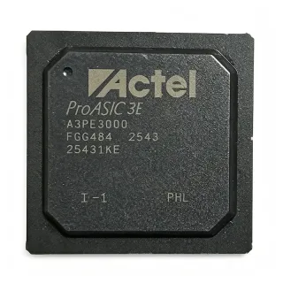
LFE2-50E-6F484I - 48K LUT ECP2 FPGA | Lattice Semiconductor
MPN: LFE2-50E-6F484I ✓ 啟用中LFE2-50E-6F484I 概覽
An FPGA is a programmable semiconductor used to implement digital logic, control functions, interfaces, and signal processing in reconfigurable hardware. Within the product hierarchy, the LFE2-50E-6F484I is an ECP2 FPGA, a field-programmable gate array, and a member of the broader programmable-logic and semiconductor categories. Unlike a fixed-function logic IC, an FPGA allows its configuration bitstream to be changed during design, debugging, or product updates.
The device's principal features include 48,000 logic elements, 339 user I/O, 396,288 bits of embedded memory, a 1.2 V nominal supply, and a -6 speed grade. The large I/O count supports connections to external processors, memories, converters, and industry-standard digital interfaces. Its industrial ordering designation supports use in equipment expected to operate outside consumer-only temperature environments, although exact minimum and maximum junction or ambient limits should be confirmed in the manufacturer datasheet.
The 484-FBGA package uses 23 mm by 23 mm square construction and surface-mount assembly. This is a high-ball-count package intended for compact, multilayer printed-circuit-board layouts. The ECP2 architecture combines configurable logic and embedded memory to support parallel data processing, control logic, communications interfaces, and general-purpose embedded systems. Configuration programming and the device's supported I/O standards should be validated against the intended board schematic before layout release.
Typical applications include industrial control equipment, embedded communications systems, data-acquisition and signal-processing modules, video-format conversion, and compact embedded platforms requiring a high pin count. Its 339 I/O make it particularly relevant where parallel buses, control signals, and multiple external interfaces must coexist in one programmable device. The industrial-grade ordering option also makes it suitable for platforms designed around long-life embedded control and communications subsystems.
PCB implementation requires careful BGA fanout, controlled-impedance routing, and a solid ground-and-power distribution network. Use the manufacturer package drawing and pinout when assigning all 484 balls, and follow the recommended power, decoupling, configuration, and clocking layouts. Because the package exposes many balls and supports a broad I/O count, verify pin multiplexing and voltage constraints in the design tool before finalizing board connections.
This page consolidates the ECP2 device's key resource counts, package characteristics, ordering information, replacement considerations, and practical implementation guidance. It also distinguishes speed-grade and ordering-suffix alternatives from true cross-manufacturer drop-in options, helping engineers evaluate whether a proposed substitution preserves package, logic resources, I/O availability, and timing expectations.
直接替換替代品,適用於 LFE2-50E-6F484I — 相同封裝,腳位對腳位相容。需重新設計 PCB 的不同封裝零件不列入。
此系列的變體
與下列產品可直接替換的同系列型號: LFE2-50E-6F484I (相同外形與佔位) — 差異在於 Device Type, Logic Elements, Package, Speed Grade.
LFE2-50E-6FN484I
✅ 直接替換📋 參考替代品(不在目錄中)
LFE2-50E-7F484I
✅ 直接替換 ⚠️ 規格未經驗證📋 參考替代品(不在目錄中)
LFE2-50E-5F484I
✅ 直接替換 ⚠️ 規格未經驗證聯絡詢價
查看資料表 →LFE2-50E-7FN484I
✅ 直接替換 ⚠️ 規格未經驗證📋 參考替代品(不在目錄中)
LFE2-50E-5FN484I
✅ 直接替換 ⚠️ 規格未經驗證📋 參考替代品(不在目錄中)
LFE2-50E-6F484I 最大額定值與電氣特性
| Device Type | ECP2 Field-Programmable Gate Array (FPGA) |
| Logic Elements | 48,000 cells |
| Lookup Tables | 48K LUTs |
| User I/O | 339 I/O |
| Embedded Memory | 396,288 bit |
| Core Supply Voltage | 1.2 V nominal |
| Operating Supply Range | 1.14 V to 1.26 V |
| Speed Grade | -6 |
| Technology | 90 nm |
| 封裝 | 484-FBGA |
| Package Dimensions | 23 mm x 23 mm |
| Terminal Count | 484 terminals |
| Terminal Form | Ball |
| Package Shape | Square |
| 安裝類型 | Surface mount |
| Temperature Grade | Industrial |
| Shipping Format | Tray |
LFE2-50E-6F484I square 腳位配置指南
LFE2-50E-6F484I(square 封裝)的腳位配置。 此數位 IC 包含 GPIO、通訊介面(UART、SPI、I2C)與電源腳位。替代腳位功能與配置選項請參閱製造商資料表。對嵌入式系統設計與 PCB 佈局至關重要。

無詳細腳位定義資料: LFE2-50E-6F484I.
請參閱 資料表 以查看完整腳位配置。
典型應用
LFE2-50E-6F484I 適用於 6 應用s: Industrial Control Systems, Embedded Communications Equipment, Data Acquisition and Signal Processing, Video Format Conversion, Embedded Instrumentation, Programmable Interface Consolidation.
Industrial Control Systems
The LFE2-50E-6F484I fits industrial controllers that combine parallel I/O, programmable state machines, and local data processing. Its 48,000 logic elements provide substantial capacity for sequencing logic, interlocks, counters, and communication-control functions, while 339 user I/O support encoders, discrete sensors, actuators, and bus transceivers. The industrial ordering designation is appropriate for equipment requiring an extended industrial temperature option. Before schematic release, verify the exact ambient and junction limits, and confirm that every connected interface uses a voltage standard supported by the selected ECP2 configuration.
推薦
Embedded Communications Equipment
The LFE2-50E-6F484I is appropriate for protocol conversion, packet handling, and embedded communications gateways because it combines 48,000 logic elements with 339 I/O. Parallel interfaces can connect directly to processors, transceivers, and memory while programmable logic handles framing, filtering, buffering, or test logic. The 396,288 embedded-memory bits provide local resources for packet queues, state tables, and dual-port data paths. Its -6 speed grade should be checked against the worst-case system clock and I/O timing, particularly for high-speed parallel buses operating close to the device's timing limits.
推薦
Data Acquisition and Signal Processing
The LFE2-50E-6F484I supports parallel data-acquisition architectures in which sampling control, digital filtering, channel multiplexing, and interface conversion are implemented as programmable logic. Its 339 I/O allow the FPGA to connect to multiple converters, memory devices, and digital control components, while 48,000 logic elements can process multiple parallel channels. The 396,288 bits of embedded memory can buffer captured data or hold coefficient and control tables. System timing must be evaluated at the selected -6 speed grade, and analog input bandwidth and conversion latency must be analyzed separately from the FPGA's digital timing.
推薦
Video Format Conversion
The LFE2-50E-6F484I can implement video timing generation, pixel conversion, scaling, and interface adaptation in programmable logic. Its 339 I/O provide substantial parallel connectivity for pixel data, synchronization signals, and control registers, while 48,000 logic elements support complete digital datapaths and frame-handling functions. The embedded-memory capacity can hold line buffers, lookup tables, or temporary frame data. The device's 484-FBGA package helps preserve board area in compact systems, but high-speed memory and video interfaces require disciplined signal-integrity, clocking, and impedance-control layouts.
推薦
Embedded Instrumentation
The LFE2-50E-6F484I is suitable for compact instrumentation platforms that combine acquisition logic, timing control, status reporting, and host communication. The 48,000 logic elements can implement multiple acquisition channels, trigger logic, calibration tables, and test-sequence control, while 339 I/O expose parallel measurement and communication interfaces. The 396,288 embedded-memory bits support local buffers and configuration data without requiring an external memory device in every design. For laboratory or industrial instrumentation, check the exact temperature ratings, verify supported I/O standards against attached converters, and rerun static timing after any speed-grade substitution.
推薦
Programmable Interface Consolidation
The LFE2-50E-6F484I can consolidate several legacy parallel interfaces into a modern processor-based platform. With 339 I/O and 48,000 logic elements, the FPGA can translate bus widths, implement protocol bridges, arbitrate peripheral access, and isolate timing between subsystems. Embedded memory can support FIFO boundaries and command queues where the host and target buses operate at different rates. This makes the device useful for industrial and communications equipment with legacy copper interfaces. Validate each voltage domain against the supported I/O standards and confirm that the complete 484-ball power and ground arrangement follows the manufacturer layout guidance.
推薦
推薦產品摘要
工程參考資料,適用於 LFE2-50E-6F484I — 比較、設計指引及合規資訊。
選型指南
與替代品比較
| 參數 | 本產品 | LFE2-50E-6FN484I | LFE2-50E-7F484I | LFE2-50E-5F484I | LFE2-50E-7FN484I | LFE2-50E-5FN484I |
|---|---|---|---|---|---|---|
| Brand | Lattice Semiconductor | Lattice Semiconductor | Lattice Semiconductor | Lattice Semiconductor | Lattice Semiconductor | Lattice Semiconductor |
| Package | 484-FBGA, 23 mm x 23 mm | 484-BBGA | 484-FBGA | 484-FBGA | 484-FBGA | 484-FBGA |
| Logic Elements | 48,000 cells / 48K LUTs | 48,000 cells | 48K LUTs | 48K LUTs | 48K LUTs | 48K LUTs |
| User I/O | 339 I/O | 339 I/O | 339 I/O | 339 I/O | 339 I/O | 339 I/O |
| Core Supply Voltage | 1.2 V nominal; 1.14 V to 1.26 V | 1.2 V | 1.2 V | 1.2 V | 1.2 V | 1.2 V |
| Speed Grade | -6 | -6 | -7 | -5 | -7 | -5 |
| Process Technology | 90 nm | 90 nm | 90 nm | 90 nm | 90 nm | 90 nm |
| Temperature Grade | Industrial | Industrial | Industrial | Industrial | Industrial | Industrial |
主要差異化特點
- Closest listed same-speed alternative retains the core resource profile (對比LFE2-50E-6FN484I)
- Faster -7 family option preserves the package and resource count (對比LFE2-50E-7F484I)
- Lower-power-speed option supports cost-down only after timing verification (對比LFE2-50E-5F484I)
- High-pin-count integration reduces external logic around parallel interfaces (對比LFE2-50E-6FN484I)
設計說明
Use the manufacturer 484-FBGA package drawing and recommended land pattern rather than estimating ball geometry from the 23 mm square body. The LFE2-50E-6F484I exposes 484 balls for power, ground, configuration, clocks, and 339 user I/O. Preserve escape-routing channels between BGA rows, place decoupling capacitors near their associated supply balls, and route high-speed nets through controlled-impedance layers. Check assembly capability and via-in-pad or solder-mask requirements before releasing the fabrication package.
Plan the 1.2 V nominal core rail for the complete 1.14 V to 1.26 V listed operating range and implement separate clean distribution paths for the FPGA core and user-I/O banks. Follow the manufacturer guidance for bypass capacitors, power sequencing, and supply current limits. Do not share narrow supply traces between multiple ball rows or distant banks. Measure ripple and droop at the device under worst-case switching activity because the 48,000-cell ECP2 can present a rapidly changing dynamic load.
The 339 available I/O do not imply that every bank can operate at the same voltage or frequency. Assign banks by voltage compatibility, review the ECP2 I/O standards for each interface, and preserve continuous return paths beneath high-speed routes. Pay particular attention to clocks, memory interfaces, and source-synchronous links. Use the design tool's timing analysis with the correct -6 speed grade and revalidate any -5 or -7 substitution rather than assuming equivalent timing margin.
Do not substitute solely by matching the 484-ball package count. Verify the exact ECP2 device, package option, speed grade, temperature grade, and complete ball assignment. The LFE2-50E-6FN484I appears as a close same-family alternative, while -5 and -7 options change the speed number by approximately 16.7 percent relative to -6. Also verify configuration programming, JTAG connections, supported I/O standards, and memory resources before approving any board spin with a different ordering code.
合規資訊
The target is an industrial-temperature ECP2 FPGA, but no explicit RoHS, REACH, lead-free, halogen-free, or conflict-minerals statement was identified. Automotive qualification is not indicated, so AEC-Q100 is treated as not applicable rather than qualified.