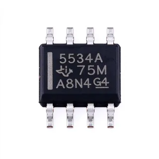
LM393ADG4 - Dual Open-Collector Comparator, 2V-36V, 8-SOIC | Texas Instruments
MPN: LM393ADG4 ✓ 啟用中LM393ADG4 概覽
A comparator is a differential analog input IC that reports whether one input voltage is above or below a reference voltage, producing a logic-level output rather than an analog amplified signal. Within the wider hierarchy, a comparator sits between simple logic gates and operational amplifiers: it belongs to the analog signal-chain family of integrated circuits, alongside amplifiers and voltage references, and is normally used inside the power-management and sensing portion of a system rather than in the digital datapath.
Key features of the LM393ADG4 include two independent channels in one 8-SOIC package, an open-collector (open-drain) output stage that requires an external pull-up resistor, single-supply or dual-supply operation, and input common-mode operation down to ground so the device can monitor low-voltage signals referenced to 0 V without a negative rail. Because the output is open-collector, the output high level is set by the pull-up and the supply rail, which allows the part to be level-shifted to any compatible logic voltage and allows several open-collector outputs to be wired together.
Internally the LM393 family uses a classic bipolar differential input stage with an open-collector output driver, and the A-grade device is characterized for general-purpose supply and input conditions. The datasheet lists supply voltages tested at 30 V for non-V devices and 32 V for V-suffix devices, giving adequate margin above the nominal 36 V absolute maximum supply rating.
Typical applications include window comparators for overvoltage and undervoltage protection, zero-cross and threshold detection for signal conditioning, relay or solenoid drive stages, sensor interface front ends for thermistors and light sensors, and battery monitoring in portable equipment. The open-collector output also makes the device suitable for driving indicator LEDs or optocouplers directly with a series current-limiting resistor.
When designing with the LM393ADG4, remember that the open-collector output cannot source current: every output needs a pull-up resistor, typically between 1 kΩ and 10 kΩ, and the pull-up supply defines the logic high level. Keep the input common-mode voltage within the rated range and place the pull-up resistor close to the output to keep rise times short when driving capacitive loads.
直接替換替代品,適用於 LM393ADG4 — 相同封裝,腳位對腳位相容。需重新設計 PCB 的不同封裝零件不列入。
此系列的變體
與下列產品可直接替換的同系列型號: LM393ADG4 (相同外形與佔位) — 差異在於 Output Type, Package, Response Time.
LM393BDR
✅ 直接替換📋 參考替代品(不在目錄中)
LM2903DR
✅ 直接替換聯絡詢價
查看資料表 →LM393AIDG4
✅ 直接替換📋 參考替代品(不在目錄中)
LM393AD-T
✅ 直接替換📋 參考替代品(不在目錄中)
LM393ADG4 最大額定值與電氣特性
| Number of Elements | 2 |
| Comparator Type | Dual Differential Comparator |
| 輸出類型 | Open-Collector (CMOS, MOS, TTL compatible) |
| Supply Voltage Range (single supply) | 2 V to 36 V |
| Supply Voltage Range (dual supply) | ±1 V to ±18 V |
| Input Common-Mode Range | Includes ground (rail-to-rail common-mode input) |
| Response Time | 0.3 µs |
| Tested Supply Voltage (non-V devices) | 30 V |
| Tested Supply Voltage (V-suffix devices) | 32 V |
| Supply Configuration | Single supply or dual (split) supplies |
| 封裝 | 8-SOIC (0.154 in, 3.90 mm width) |
| 安裝類型 | Surface Mount |
| 腳位數 | 8 |
LM393ADG4 腳位配置
| 腳位 1 | OUT1 — Comparator 1 output (open collector) |
| 腳位 2 | IN1- — Comparator 1 inverting input |
| 腳位 3 | IN1+ — Comparator 1 non-inverting input |
| 腳位 4 | GND — Ground |
| 腳位 5 | IN2+ — Comparator 2 non-inverting input |
| 腳位 6 | IN2- — Comparator 2 inverting input |
| 腳位 7 | OUT2 — Comparator 2 output (open collector) |
| 腳位 8 | VCC — Positive supply |
典型應用
LM393ADG4 適用於 6 應用s: Overvoltage and Undervoltage Window Protection, Industrial Sensor Signal Conditioning, Relay, Solenoid and Lamp Drive Stage, Zero-Crossing and Threshold Detection, Battery Pack Monitoring, Audio and Amplifier Cut-Off Detection.
Overvoltage and Undervoltage Window Protection
The LM393ADG4 suits window comparators because its input common-mode voltage range includes ground, so a divided sense line referenced to 0 V can be compared without a negative supply rail. Two channels give independent overvoltage and undervoltage thresholds, each comparing a resistor-divided version of the monitored rail against a reference taken from the supply. With a 0.3 µs response time the device reacts quickly enough to trip a crowbar or disable a load switch before downstream damage accumulates. Tie the two open-collector outputs to a single pull-up to create a combined fault flag that deasserts only while the rail remains inside the acceptable window, and size the divider resistors for the minimum quiescent current acceptable in your rail.
推薦
Industrial Sensor Signal Conditioning
Thermistors, RTDs, and light sensors all produce slowly changing analog signals that must be converted into a digital threshold event, and the LM393ADG4 performs that conversion directly. The input stage accepts signals close to ground, which suits sensors biased from a single positive rail, while the open-collector output can drive a PLC input module, a relay coil, or an optocoupler LED with a series current-limiting resistor. A 0.3 µs response time allows the comparator to act as a fast Schmitt trigger with intentional hysteresis added by positive feedback to suppress chatter around the threshold. In factory equipment, placing the device close to the sensor reduces noise pickup on the high-impedance divider, and the wide 2 V to 36 V supply range lets the same part work across 5 V, 12 V, and 24 V control cabinets.
推薦
Relay, Solenoid and Lamp Drive Stage
Because the LM393ADG4 output is open-collector rather than totem-pole, it is a natural fit for driving inductive and indicator loads. The output sinks the load current into ground, and a pull-up resistor returns the node to the logic rail when the comparator deasserts, so the load is energized while the output is low, which is easy to map to fail-safe system logic. This arrangement works well with relay coils, solenoids, and status LEDs, and it also allows the pull-up rail to be a different voltage from the comparator supply for level shifting into an older logic family. The output stage is rated for continuous sink current rather than source current, so size the coil current against the output sink rating and add a flyback diode across any inductive load to suppress the back-EMF spike.
推薦
Zero-Crossing and Threshold Detection
Zero-cross detection around a bipolar signal is a classic use for the LM393 family, and the LM393ADG4 adds a wide supply range so the comparator can sit directly on the signal being monitored. Feeding the AC-coupled signal into the non-inverting input with a bias network referenced to the midpoint of the split supply lets the device switch state at each polarity reversal, producing a clean edge for a timer input or an interrupt line. The 0.3 µs response time keeps the edge delay small relative to the switching period, which matters in motor control and mains-frequency detection. For noisy inputs, add hysteresis with positive feedback and place a small RC filter at the input so that the comparator does not toggle repeatedly on noise riding on the zero crossing.
推薦
Battery Pack Monitoring
In portable and energy-storage equipment the LM393ADG4 can watch the pack voltage without a negative supply, because the input common-mode voltage range includes ground and the supply range extends to 36 V for higher-voltage stacks. A resistive divider feeds one channel to detect over-discharge, while the second channel detects over-charge, giving a complete two-threshold window with only one package. The low quiescent current of this bipolar dual comparator family makes it practical for always-on battery monitoring, and the open-collector output can directly pull down an enable line or a fuel-gauge interrupt. Choose pull-up resistor values that keep standby current low, and remember that the output can only sink current, so the load it controls must sit in the pull-up path rather than being driven from the output pin.
推薦
Audio and Amplifier Cut-Off Detection
Audio systems use the LM393ADG4 as a hard clip and mute detector. The signal is divided down and compared against a reference on one channel while the opposite polarity is compared on the other, so overdrive is caught in either direction before it reaches the output stage. The 0.3 µs response time makes the detection fast enough to mute a channel within a fraction of a millisecond, which is short enough to be inaudible. The open-collector output can pull a mute control or a relay directly, and the wide supply range lets the detector run from the same rail as the amplifier section. Keep the input divider impedance high enough to avoid loading the audio path, and use a dedicated comparator input filter rather than sharing a noisy ground return with the power amplifier.
推薦
推薦產品摘要
工程參考資料,適用於 LM393ADG4 — 比較、設計指引及合規資訊。
選型指南
與替代品比較
| 參數 | 本產品 | LM393BDR | LM2903DR | LM393AIDG4 | LM393AD-T | LM393DT |
|---|---|---|---|---|---|---|
| Brand | Texas Instruments | Texas Instruments | Texas Instruments | Texas Instruments | NXP Semiconductors | STMicroelectronics |
| Package | 8-SOIC (0.154 in, 3.90 mm width) | 8-SOIC - same | 8-SOIC - same | 8-SOIC - same | 8-SOIC - same | 8-SOIC - same |
| Number of Elements | 2 | 2 | 2 | 2 | 2 | 2 |
| Output Type | Open-Collector (TTL, CMOS, MOS compatible) | Open-Collector | Open-Collector | Open-Collector | Open-Collector | Open-Collector |
| Supply Voltage Range | 2 V to 36 V (single) / ±1 V to ±18 V (dual) | 2 V to 36 V | 2 V to 36 V | 2 V to 36 V | 2 V to 36 V | 2 V to 36 V |
| Input Common-Mode Range | Includes ground (rail-to-rail common-mode input) | Includes ground | Includes ground | Includes ground | Includes ground | Includes ground |
| Response Time | 0.3 µs | 1.3 µs typical propagation delay, B-version improved | Comparable to the A-grade device | 0.3 µs | Manufacturer-specific, confirm in datasheet | Manufacturer-specific, confirm in datasheet |
| Temperature Grade | Standard A grade (commercial/industrial general purpose) | Standard grade with improved B-version specifications | Extended-temperature grade | Industrial temperature grade | Standard commercial grade | Standard commercial grade |
| Supply Configuration | Single supply or dual supplies | Single or split supplies | Single or split supplies | Single or split supplies | Single or split supplies | Single or split supplies |
主要差異化特點
- Single package provides two independent channels with an identical open-collector interface (對比LM2904P3)
- Wide supply range from 2 V to 36 V on a single rail (對比LM393DT)
- Input common-mode range includes ground for zero-referenced sensing (對比LM393AD-T)
- 0.3 µs response time suits fast protection and detection loops (對比LM393BDR)
設計說明
The most common design error with the LM393ADG4 is forgetting the pull-up resistor. The open-collector output can only sink current, so every OUT pin needs a pull-up to the desired logic rail, typically 1 kΩ to 10 kΩ. A second frequent mistake is driving the output pin as a source, for example powering an LED directly from OUT; the correct arrangement is to connect the load between the pull-up rail and the output so the output sinks the load current. A third is exceeding the common-mode input range: both inputs must stay within the rated range, which includes ground but not a positive rail beyond the supply.
Place the pull-up resistor close to the comparator output pin to keep the rise time short when the node capacitance is high, since the open-collector pull-up sets the RC time constant of every rising edge. Route the differential comparator inputs away from switching nodes and keep the input traces short, because the input bias current of a bipolar comparator flows through the source impedance and converts into an offset voltage. If the divider resistors are high value (above 100 kΩ), add a small capacitor at the input to filter noise, but check that this does not slow the response of a protection loop. Decouple the supply pin with a 0.1 uF ceramic capacitor placed close to the device, plus a bulk capacitor near the supply source.
Estimated: with a 10 kOhm pull-up and a total node capacitance of 50 pF, the output rise time is about 10 x 10 kOhm x 50 pF = 5 us, which can dominate the propagation delay of the comparator itself for short events. Using a 1 kOhm pull-up reduces that to roughly 0.5 us but increases the sink current drawn during a logic-low condition to about 36 mA at a 36 V supply, so verify that against the output sink rating before reducing the resistance. Add intentional hysteresis with positive feedback from OUT to IN+ when the input signal is noisy, otherwise the comparator will chatter around the threshold.
The quiescent supply current of this bipolar comparator family flows continuously whenever the supply is present, which matters in battery-powered designs. Where the design allows it, power the comparator from a switched supply rail or use the enable/shutdown functions of the surrounding system to cut it off during idle periods. When two devices are compared on current draw, check both the typical and maximum quiescent figures in the manufacturer datasheet at the actual supply voltage, since the current rises with supply. If standby current dominates the design, a CMOS-input dual comparator family offers substantially lower consumption but a different output structure and usually a lower maximum supply voltage.
合規資訊
This legacy general-purpose dual comparator is not positioned as an automotive-qualified part. Obtain current RoHS, REACH, and lead-free declarations for the exact orderable part number from the manufacturer before production release.