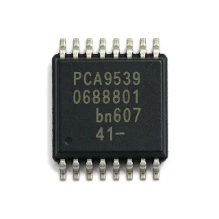
MAX232EIPWG4 - Dual RS-232 Interface | Texas Instruments
MPN: MAX232EIPWG4 ✓ 啟用中MAX232EIPWG4 概覽
An RS-232 transceiver is an interface IC that translates logic-level signals into RS-232 voltage levels and converts incoming RS-232 signals back into logic levels. It belongs to the interface IC hierarchy, connects digital equipment to serial communication equipment, and handles the voltage conversion that the RS-232 standard requires. The MAX232EIPWG4 uses an internal charge-pump circuit to generate the positive and negative voltages needed by its two RS-232 drivers.
Key features include two integrated drivers, two integrated receivers, operation from one 5 V power supply, 120 kbit/s operation, plus or minus 30 V receiver input capability, and IEC 61000-4-2 protection. The protected receiver inputs are particularly useful where cables connect to external equipment and electrostatic discharge may enter the system through the serial connector. Its integrated charge-pump design simplifies interface implementation compared with discrete level-shifting networks.
Technically, the MAX232EIPWG4 combines RS-232 line drivers, RS-232 receivers, and regulated charge pumps in one package. The 1.0 uF charge-pump capacitors establish the internal voltage rails used by the drivers. Receiver inputs tolerate plus or minus 30 V levels, allowing the interface to remain connected to standard RS-232 ports when the local logic supply is 5 V. The device is intended for industrial-temperature operation, with a gull-wing TSSOP package suited to conventional surface-mount PCB assembly.
Typical uses include industrial serial-control panels, test and measurement equipment, point-of-sale terminals, service-console links, and data-acquisition equipment. The dual-channel arrangement allows one device to support two RS-232 ports when both transmit and receive lines are required. Its 120 kbit/s capability is appropriate for legacy serial protocols, configuration interfaces, and equipment-control links rather than modern high-speed Ethernet or USB communication.
PCB implementation should follow the manufacturer datasheet's charge-pump capacitor connection and keep the MAX232EIPWG4 close to the RS-232 connector. Confirm capacitor voltage rating, polarity, and placement against the datasheet requirements. Protect connector-side routing from unintended board contamination, and maintain suitable ground-return continuity between connected equipment. For a new design, verify that the remote equipment still uses RS-232 rather than RS-422, RS-485, or another differential interface.
This page combines the device's stated electrical characteristics with application guidance, package-aware selection criteria, and verified drop-in alternatives. It also distinguishes true same-footprint replacements from parts that merely perform the same RS-232 function but require a different PCB footprint.
直接替換替代品,適用於 MAX232EIPWG4 — 相同封裝,腳位對腳位相容。需重新設計 PCB 的不同封裝零件不列入。
此產品無可直接替換的替代品。
申請替代品MAX232EIPWG4 規格
| Product Type | Dual RS-232 driver/receiver interface IC |
| Number of Drivers | 2 |
| Number of Receivers | 2 |
| 供應電壓 | 5 V |
| Maximum Data Rate | 120 kbit/s |
| Charge-Pump Capacitor Value | 1.0 uF |
| Receiver Input Voltage Range | -30 V to +30 V |
| ESD Protection Standard | IEC 61000-4-2 |
| RS-232 Compliance | TIA/RS-232-F |
| ITU Recommendation | V.28 |
| Temperature Grade | Industrial |
| Package Type | TSSOP-16 |
| Terminal Count | 16 |
| Terminal Form | Gull wing |
| Package Shape | Rectangular |
| 安裝類型 | Surface mount |
MAX232EIPWG4 rectangular 腳位配置指南
MAX232EIPWG4(rectangular 封裝)的腳位配置。 腳位編號、功能與連接圖定義於製造商資料手冊中。請參閱該手冊以取得確切的封裝尺寸與焊接指引。

無詳細腳位定義資料: MAX232EIPWG4.
請參閱 資料表 以查看完整腳位配置。
典型應用
MAX232EIPWG4 適用於 6 應用s: Industrial Serial Control Panels, Test and Measurement Equipment, Point-of-Sale Terminals, Data-Acquisition Systems, Service and Configuration Consoles, Instrumentation and Process-Control Links.
Industrial Serial Control Panels
The MAX232EIPWG4 fits a dual-channel industrial control panel that must communicate with legacy RS-232 equipment through a single 5 V logic supply. Its two drivers and two receivers support two bidirectional serial links, while operation up to 120 kbit/s covers many configuration and service protocols. The plus or minus 30 V receiver input capability and IEC 61000-4-2 protection add margin at connector-facing inputs. Place the device near the serial connectors, route the charge-pump network compactly, and verify the industrial temperature range against the complete system enclosure.
推薦
Test and Measurement Equipment
The MAX232EIPWG4 is suitable for test and measurement instruments that expose a legacy RS-232 configuration or service port while operating from 5 V. Two integrated driver/receiver channels can reduce the component count when the instrument supports multiple serial links. Its 120 kbit/s rate is appropriate for command consoles, calibration routines, and low-speed data-transfer interfaces. The protected receiver inputs help manage electrostatic-discharge exposure associated with user-accessible cabling, although the connector, chassis grounding, and cable design remain important parts of the protection strategy.
推薦
Point-of-Sale Terminals
The MAX232EIPWG4 can support RS-232 peripherals commonly found around point-of-sale systems, including scales, printers, or customer displays with legacy serial interfaces. Its dual-channel structure allows two complete bidirectional ports when both directions are needed, and its single 5 V supply simplifies integration with equipment that already uses 5 V logic. The 120 kbit/s data rate covers many short-distance peripheral protocols. Place the transceiver close to the connector, maintain a continuous signal-ground path, and check whether the attached peripheral requires hardware handshaking before allocating the available pins.
推薦
Data-Acquisition Systems
The MAX232EIPWG4 is a practical interface between a 5 V data-acquisition controller and external RS-232 instruments. Two receivers can collect status or command information from separate ports, while the drivers return configuration and control data. The 120 kbit/s limit suits low-bandwidth acquisition-control traffic rather than continuous high-rate sensor streaming. The integrated IEC 61000-4-2 protection is useful when cables enter the enclosure from uncontrolled environments, but engineers should still use a suitable connector, short unprotected stub strategy, and chassis-to-signal-ground design appropriate to the installation.
推薦
Service and Configuration Consoles
The MAX232EIPWG4 is appropriate for embedded equipment with a service port used during installation, calibration, or maintenance. A 120 kbit/s RS-232 channel provides sufficient bandwidth for command exchanges, diagnostic output, and firmware-transfer workflows, while the dual-driver/receiver arrangement permits two ports on space-constrained boards. The single 5 V operating supply aligns with many embedded control platforms. Engineers should document boot-loader behavior, isolate the service connector when it is not in use, and test the interface with the actual service cable because capacitance and connector geometry can influence signal integrity.
推薦
Instrumentation and Process-Control Links
The MAX232EIPWG4 can bridge a compact controller to legacy RS-232 instrumentation used in process-control or laboratory systems. Its two independent channels reduce the footprint needed for separate single-channel transceivers, and the 5 V supply requirement supports embedded control designs. The plus or minus 30 V receiver input range is useful for standard RS-232 signaling, while the stated ESD protection helps at externally cabled interfaces. Verify grounding and isolation requirements, especially when connecting equipment at different earth potentials, because the IC does not by itself provide galvanic isolation.
推薦
推薦產品摘要
工程參考資料,適用於 MAX232EIPWG4 — 比較、設計指引及合規資訊。
選型指南
主要差異化特點
- Combines two complete RS-232 channels with protected receiver inputs (對比Single-channel RS-232 interface)
- Supports legacy serial data rates up to 120 kbit/s (對比Higher-bandwidth RS-232 transceiver)
- Uses a compact 16-pin TSSOP footprint (對比MAX232IN)
設計說明
Use the pin-configuration table in the manufacturer datasheet when creating the PCB symbol and footprint. Place the two 1.0 uF charge-pump capacitors close to their designated pins, minimize the loop area, and route the RS-232 connector-side nets away from sensitive analog and high-speed digital traces. Confirm the exposed package dimensions and terminal numbering against the selected 16-pin TSSOP drawing before releasing artwork.
Do not treat a functionally similar SOIC or SOIC-W RS-232 transceiver as a board-level replacement. The available MAX232IN comparison identifies a 16-pin SOIC package, whereas MAX232EIPWG4 uses 16-pin TSSOP; changing between them requires a different footprint and pin assignment. Confirm connector gender, signal-ground wiring, and remote-device logic levels before selecting the interface IC.
Keep the RS-232 receive paths away from switching nodes and long parallel runs of high-current power wiring. Maintain a continuous ground reference between the board and connected equipment, and apply the manufacturer's charge-pump capacitor placement guidance. If a cable can be touched by an operator, supplement the IC's IEC 61000-4-2 receiver protection with appropriate connector, enclosure, and grounding measures.
合規資訊
The manufacturer documentation identifies IEC 61000-4-2 protection, TIA/RS-232-F compliance, and ITU Recommendation V.28. RoHS, REACH, lead-free, halogen-free, and conflict-minerals status are not stated.