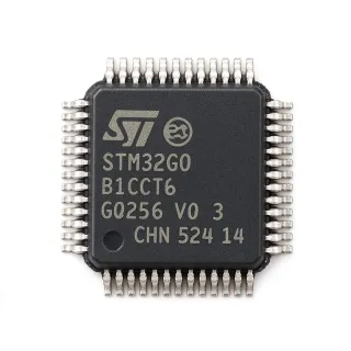
STM32F334R6T6 - 72MHz Cortex-M4 32KB MCU | STMicroelectronics
MPN: STM32F334R6T6 ✓ 啟用中STM32F334R6T6 概覽
A microcontroller is a programmable semiconductor that integrates a processor core, memory and peripheral interfaces into one device. The STM32F3 family belongs to the ARM Cortex-M microcontroller hierarchy, combining low-power embedded processing with timers, communication interfaces and analog functions. The STM32F334R6T6 is particularly suited to applications where real-time control, compact implementation and a relatively high timer update rate are important.
The most prominent device characteristics are its 72 MHz maximum operating frequency, 32 KB Flash program memory and 16 KB SRAM. Its 64-LQFP package provides access to a substantial set of general-purpose and peripheral pins while retaining a compact 10 x 10 mm body. The high-resolution timer supports applications requiring precise timing, while the Cortex-M4 architecture provides efficient fixed-point and single-precision floating-point processing for control algorithms and digital signal processing.
The STM32F334R6T6 is positioned as a mixed-signal MCU within the STM32F3 family. It combines the processor and embedded memories with timers, serial interfaces and analog peripherals on one package. Firmware determines the operating behavior, peripheral allocation and real-time control performance. Designers should allocate the available Flash and SRAM for the application, interrupt handlers, bootloader and any safety margin rather than treating the nominal memory capacity as entirely available to application code.
Typical uses include digital motor controllers, precision timers, industrial automation modules, sensor acquisition systems, communication equipment and compact embedded-control boards. The 72 MHz processing rate supports responsive control loops, while the high-resolution timer is useful when an application must measure narrow timing intervals or generate precise timing relationships.
The principal design consideration is pin and power planning. Because the MCU exposes 64 pins in a relatively small LQFP footprint, a multilayer board is generally preferable for dependable routing of power, ground, communication signals and timer outputs. Decoupling capacitors should be placed close to the supply pins, and unused inputs should be configured to avoid floating states. Firmware and peripheral configuration must also be reviewed before assuming that a different STM32F3 device is a functionally equivalent replacement.
This product overview consolidates the confirmed processor, memory, package and supply information into an engineering-oriented format. It also provides drop-in candidate analysis, application guidance, comparison parameters and design notes intended to accelerate component selection without treating pin compatibility as proof of identical firmware behavior.
直接替換替代品,適用於 STM32F334R6T6 — 相同封裝,腳位對腳位相容。需重新設計 PCB 的不同封裝零件不列入。
此系列的變體
與下列產品可直接替換的同系列型號: STM32F334R6T6 (相同外形與佔位) — 差異在於 Flash Memory, Package, SRAM.
STM32F334R6T5
✅ 直接替換 ⚠️ 規格未經驗證📋 參考替代品(不在目錄中)
STM32F302R6T6
✅ 直接替換 ⚠️ 規格未經驗證📋 參考替代品(不在目錄中)
STM32F303R6T6
✅ 直接替換 ⚠️ 規格未經驗證📋 參考替代品(不在目錄中)
STM32F334R8T6
✅ 直接替換 ⚠️ 規格未經驗證聯絡詢價
查看資料表 →STM32F334R4T6
✅ 直接替換 ⚠️ 規格未經驗證📋 參考替代品(不在目錄中)
STM32F334R6T6 最大額定值與電氣特性
| Product Type | 32-bit ARM Cortex-M4 microcontroller |
| Maximum CPU Frequency | 72 MHz |
| CPU Architecture | ARM Cortex-M4 |
| Instruction Set Width | 32 bit |
| Flash Memory | 32 KB |
| SRAM | 16 KB |
| 工作電源電壓 | 3.3 V |
| 封裝 | 64-pin LQFP, 10 x 10 mm |
| 腳位數 | 64 pins |
| 安裝類型 | Surface mount |
| Timer Feature | High-resolution timer |
| Floating-Point Support | Single-precision floating point |
| Core Architecture | High-performance 32-bit RISC |
| Packaging Type | Tray |
STM32F334R6T6 64-pin lqfp, 10 x 10 mm 腳位配置指南
STM32F334R6T6(64-pin lqfp, 10 x 10 mm 封裝)的腳位配置。 此數位 IC 包含 GPIO、通訊介面(UART、SPI、I2C)與電源腳位。替代腳位功能與配置選項請參閱製造商資料表。對嵌入式系統設計與 PCB 佈局至關重要。

無詳細腳位定義資料: STM32F334R6T6.
請參閱 資料表 以查看完整腳位配置。
典型應用
STM32F334R6T6 適用於 6 應用s: Precision DC Motor Control, Industrial Sensor Acquisition, Digital Power Converter Control, Communication Equipment Controller, Precision Timing Module, Embedded Control and HMI Module.
Precision DC Motor Control
The STM32F334R6T6 fits compact DC motor controllers that need deterministic timing without a large external processor. Its 72 MHz ARM Cortex-M4 core can execute proportional-integral-derivative control loops, current sampling logic and protection handling, while the high-resolution timer supports precise PWM updates and time measurements. In a typical 3.3 V control architecture, the MCU evaluates current and position feedback, updates the power-stage command and manages faults. The 64-pin LQFP also provides enough external connections for encoder inputs, Hall sensors, PWM outputs and communications. Designers should reserve timer resources for the control loop and verify the family datasheet for the exact channel assignments and complementary-output options used by the selected motor driver.
推薦
Industrial Sensor Acquisition
The STM32F334R6T6 is appropriate for industrial measurement modules that combine sensor conditioning with local computation. The 72 MHz Cortex-M4 processor can filter, calibrate and transmit measurements from analog or digital sensors, while its 16 KB SRAM supports buffering and real-time acquisition tasks. The 64-pin LQFP package exposes multiple I/O options for sensor interfaces, status indicators and field-bus links. A practical implementation uses the MCU for timestamped sampling, filtering and diagnostics rather than attempting to perform all signal conditioning inside the MCU. Because the product listing confirms the 3.3 V supply but not every analog or communication peripheral, engineers should verify the required ADC channels, comparator resources and serial interfaces against the official family datasheet before finalizing the schematic.
推薦
Digital Power Converter Control
The STM32F334R6T6 can serve as the digital controller for a compact switching power converter or digitally controlled supply. Its 72 MHz Cortex-M4 core is suitable for sampled control loops, while the high-resolution timer can improve PWM resolution and timing consistency for power conversion. In a typical design, the MCU drives a gate-circuit interface, samples feedback, updates duty cycle and manages startup or fault states. The 3.3 V control domain keeps the processor separate from higher-power switching stages, while the 64-pin package provides connections for sensing and protection signals. Final compensation design must use actual switch and diode characteristics, and the electrical requirements of the family datasheet must be checked for high-side sensing, bootstrap circuitry and fault-response timing.
推薦
Communication Equipment Controller
The STM32F334R6T6 can manage protocol handling and system control in compact communications equipment. Its 72 MHz Cortex-M4 core supports multitasking, framing, buffering and real-time response, while 32 KB of Flash accommodates a protocol stack, configuration data and application firmware. The 64-pin LQFP provides more I/O than a minimal controller and can support serial links, indicators and configuration controls. A typical implementation assigns dedicated timer and serial resources to frame timing, uses interrupts for data reception and keeps protocol latency within the application's packet deadlines. The exact UART, USB, CAN or other interface availability must be confirmed in the family documentation, since the product summaries identify the MCU family and high-resolution timer but do not enumerate every peripheral variant.
推薦
Precision Timing Module
The STM32F334R6T6 is well suited to timing-sensitive modules that measure intervals, generate synchronized events or coordinate multiple outputs. Its high-resolution timer is the central feature, while the 72 MHz Cortex-M4 core handles event filtering, calibration and reporting. In a pulse-measurement design, timer capture channels timestamp input edges and the processor converts the elapsed counts into engineering units. In a synchronized-output design, multiple timer channels establish the relative timing of control or test signals. The 64-pin LQFP allows timing inputs, trigger lines and status signals to be routed without an external complex-programmable logic device. Clock accuracy, timer prescaler resolution and input filtering determine absolute timing performance, so the final design should calculate those values from the selected oscillator configuration.
推薦
Embedded Control and HMI Module
The STM32F334R6T6 can serve as the control processor for compact embedded-control modules that include local status indication, user inputs and communications. Its Cortex-M4 architecture provides enough performance for menu logic, parameter handling, data logging and real-time background tasks, while the 64-pin package offers a broad mix of general-purpose I/O. A typical design connects buttons, indicators, a local display interface and a network or serial link, with the MCU maintaining the operating state and executing control sequences. The 32 KB Flash requirement should be checked against bootloader size and firmware growth, while the 16 KB SRAM must accommodate stack, buffers and the active operating system. Pin multiplexing should be reviewed early because display, communication and control functions can compete for the same timer, serial and GPIO resources.
推薦
推薦產品摘要
工程參考資料,適用於 STM32F334R6T6 — 比較、設計指引及合規資訊。
選型指南
與替代品比較
| 參數 | 本產品 | STM32F334R6T5 | STM32F302R6T6 | STM32F303R6T6 | STM32F334R8T6 | STM32F334R4T6 |
|---|---|---|---|---|---|---|
| Brand | STMicroelectronics | STMicroelectronics | STMicroelectronics | STMicroelectronics | STMicroelectronics | STMicroelectronics |
| Package | 64-pin LQFP (10 x 10 mm) | 64-pin LQFP (10 x 10 mm) | 64-pin LQFP (10 x 10 mm) | 64-pin LQFP (10 x 10 mm) | 64-pin LQFP (10 x 10 mm) | 64-pin LQFP (10 x 10 mm) |
| CPU Core | ARM Cortex-M4 | ARM Cortex-M4 | ARM Cortex-M4 | ARM Cortex-M4 | ARM Cortex-M4 | ARM Cortex-M4 |
| Maximum Frequency | 72 MHz | 72 MHz | 72 MHz | 72 MHz | 72 MHz | 72 MHz |
| Operating Supply | 3.3 V | 3.3 V | 3.3 V | 3.3 V | 3.3 V | 3.3 V |
| Timer Position | High-resolution timer | High-resolution timer | STM32F3 general-purpose timers; exact feature mapping required | Mixed-signal timer resources; exact mapping required | High-resolution timer | High-resolution timer |
| Floating-Point Support | Single-precision floating point | Single-precision floating point | Single-precision floating point | Single-precision floating point | Single-precision floating point | Single-precision floating point |
主要差異化特點
- Purpose-specific high-resolution timer positioning (對比STM32F302R6T6)
- Closest same-base ordering option (對比STM32F334R6T5)
- More Flash headroom in the R8 variant (對比STM32F334R8T6)
- Balanced memory configuration for control firmware (對比STM32F334R4T6)
設計說明
Reserve the 64-pin LQFP land pattern exactly as defined by the manufacturer package drawing, including exposed or thermal-related requirements where applicable. Place every supply decoupling capacitor immediately between the corresponding power and ground pins, and provide a low-impedance ground plane beneath the device. For a 10 x 10 mm LQFP, fanout, via placement and assembly clearances require particular care; use a multilayer PCB when the design needs clean return paths for high-speed or switching signals.
Estimated power consumption cannot be fixed from CPU frequency alone. Use the family datasheet current measurements at the selected clock, operating voltage and peripheral state, then calculate worst-case supply demand as I_active plus I_IO plus margin for startup and temperature. For example, at a 3.3 V rail, every additional 10 mA of average current corresponds to 33 mW of rail load; convert that current into regulator capacity requirements and thermal rise for the complete 3.3 V system.
Do not treat a matching 64-pin LQFP footprint as proof of a drop-in replacement. Compare the pin table, alternate-function mapping, timer channels, ADC inputs, clock pins, debugging interface and absolute maximum ratings between the original and candidate device. The STM32F334R6T6 is distinguished by its high-resolution timer, so designs that depend on that peripheral require an explicit resource-level review before approving a substitute.
Assign oscillator, debug and high-speed communication nets before committing the PCB layer stack, because these signals often require short paths and continuous return references. Keep crystal or clock traces away from switching-node and high-current power paths, and avoid routing sensitive timer-capture signals parallel to fast digital edges. If the MCU controls a switching converter, separate the power stage from the sensing path and place protection components close to their associated pins.
合規資訊
The confirmed product information does not state RoHS, REACH, AEC-Q100, lead-free, halogen-free or conflict-minerals status. Verify these requirements through the current manufacturer product documentation and purchasing records.